EP0407628A1 - Procédé et installation pour l'élimination de grandeurs périodiques perturbatrices ayant des fréquences connues et variables - Google Patents
Procédé et installation pour l'élimination de grandeurs périodiques perturbatrices ayant des fréquences connues et variables Download PDFInfo
- Publication number
- EP0407628A1 EP0407628A1 EP89112580A EP89112580A EP0407628A1 EP 0407628 A1 EP0407628 A1 EP 0407628A1 EP 89112580 A EP89112580 A EP 89112580A EP 89112580 A EP89112580 A EP 89112580A EP 0407628 A1 EP0407628 A1 EP 0407628A1
- Authority
- EP
- European Patent Office
- Prior art keywords
- signal
- variable
- frequency
- disturbance
- output
- Prior art date
- Legal status (The legal status is an assumption and is not a legal conclusion. Google has not performed a legal analysis and makes no representation as to the accuracy of the status listed.)
- Granted
Links
- 230000000737 periodic effect Effects 0.000 title claims abstract description 13
- 238000000034 method Methods 0.000 title claims description 16
- 238000012937 correction Methods 0.000 claims abstract description 28
- 230000001419 dependent effect Effects 0.000 claims abstract description 10
- 230000006870 function Effects 0.000 claims description 75
- 238000012546 transfer Methods 0.000 claims description 49
- 230000004044 response Effects 0.000 claims description 19
- 230000000694 effects Effects 0.000 claims description 6
- 230000010355 oscillation Effects 0.000 claims description 6
- 238000005259 measurement Methods 0.000 claims description 4
- 238000004088 simulation Methods 0.000 claims description 4
- 230000001629 suppression Effects 0.000 claims 1
- 238000004364 calculation method Methods 0.000 abstract description 4
- 230000005540 biological transmission Effects 0.000 description 16
- 238000005096 rolling process Methods 0.000 description 5
- 238000010586 diagram Methods 0.000 description 4
- 230000008030 elimination Effects 0.000 description 3
- 238000003379 elimination reaction Methods 0.000 description 3
- 238000013016 damping Methods 0.000 description 2
- 238000009499 grossing Methods 0.000 description 2
- 238000006243 chemical reaction Methods 0.000 description 1
- 238000013461 design Methods 0.000 description 1
- 230000010363 phase shift Effects 0.000 description 1
- 238000009420 retrofitting Methods 0.000 description 1
- 238000001228 spectrum Methods 0.000 description 1
- 230000008646 thermal stress Effects 0.000 description 1
- 238000011144 upstream manufacturing Methods 0.000 description 1
Images



Classifications
-
- F—MECHANICAL ENGINEERING; LIGHTING; HEATING; WEAPONS; BLASTING
- F16—ENGINEERING ELEMENTS AND UNITS; GENERAL MEASURES FOR PRODUCING AND MAINTAINING EFFECTIVE FUNCTIONING OF MACHINES OR INSTALLATIONS; THERMAL INSULATION IN GENERAL
- F16C—SHAFTS; FLEXIBLE SHAFTS; ELEMENTS OR CRANKSHAFT MECHANISMS; ROTARY BODIES OTHER THAN GEARING ELEMENTS; BEARINGS
- F16C32/00—Bearings not otherwise provided for
- F16C32/04—Bearings not otherwise provided for using magnetic or electric supporting means
- F16C32/0406—Magnetic bearings
- F16C32/044—Active magnetic bearings
- F16C32/0444—Details of devices to control the actuation of the electromagnets
- F16C32/0451—Details of controllers, i.e. the units determining the power to be supplied, e.g. comparing elements, feedback arrangements with P.I.D. control
-
- B—PERFORMING OPERATIONS; TRANSPORTING
- B21—MECHANICAL METAL-WORKING WITHOUT ESSENTIALLY REMOVING MATERIAL; PUNCHING METAL
- B21B—ROLLING OF METAL
- B21B37/00—Control devices or methods specially adapted for metal-rolling mills or the work produced thereby
- B21B37/58—Roll-force control; Roll-gap control
- B21B37/66—Roll eccentricity compensation systems
Definitions
- the invention relates to a method for eliminating the influence of periodic disturbance variables with a known, variable frequency, which attack in particular in control loops between the actuator and the controlled system.
- periodic disturbance variables are, for example in the case of drives of design-related flow asymmetries in the machine, speed-proportional torque ripples or, in the case of electromagnetically mounted rotors, a periodic bearing load component caused by a rotating balancing force.
- the object of the invention is to provide a parallel disturbance variable elimination which is effective over the controlled system without a control-effect circuit and which can be used to react more quickly, particularly when the frequency of the disturbance variable changes.
- the basic idea of the invention is therefore to select a signal dependent on the disturbance variable and to form the correction signal required for the disturbance variable feed-in from the selected signal by means of complex pointer calculation.
- An important advantage that results from the invention is that it works completely independently of the control loop used in each case, ie that it easily adds existing control loops or that a control is dimensioned and constructed completely independently of the disturbance variable elimination according to the invention can be.
- transfer functions ie functions of the Laplace operator s, are uniformly designated by F and values or signals provided with a " ⁇ " are understood to be those with which original sizes or signals are reproduced as well as possible.
- the input quantity of the transmission element with the transmission function F a and the output quantity of the transmission element with the transmission function F b are fed to a mixing element M via two further transmission elements with the transmission functions F 1 and F 2.
- the transfer function F2 can be any transfer function which can be implemented and which is in each case adapted to the requirements prevailing in the individual case. So that at the output of the mixer element M only a signal dependent on the disturbance variable z occurs, the influence of the signal u arriving via the transmission elements with the transfer functions F a , F b and F 2 on the input of the mixer element M must be compensated, which is achieved by means of the transfer function F 1 happens, which is such that it consists of the product of the transfer functions F ⁇ a , F ⁇ b and F2.
- the output variable of the transfer element with the transfer function F 1 is fed to the second input of the mixing element M with a negative effect.
- F ⁇ a and F ⁇ b mean replicas of the actually existing transfer functions F a and F b .
- F c e.g.
- the transfer functions F ⁇ a or F ⁇ b have unstable poles or poles that are too slow in their own movements, it is expedient to implement these undesirable poles as zeros in the transfer function F2, so that they are formally added against the same ones Shorten the zeros of F2 within F1 and therefore do not have to be implemented in F1. Otherwise, the transfer functions F2 and F c are to be selected so that the selected variable z 'swings as quickly as possible even if there are parameter inaccuracies and on the other hand measurement errors from z' are kept away.
- both the disturbance variable z and the selected signal z ' are periodic, sinusoidal variables, the frequency of which is known and thus available, it was recognized that it is still possible to implement the desired transmission behavior for the current frequency, by providing the real and imaginary part of the complex frequency response of the desired transfer function as a function of the respective value of the frequency ⁇ , i.e. either calculating it or storing it in a memory ready for retrieval, and at least one corresponding to the fundamental component of the selected signal z 'and one opposite to it by 90 ° phase-leading signal is thus amplitude-weighted and these two amplitude-weighted signals are then added.
- the complex frequency response arises in a known manner from the transfer function if the Laplace operator s is replaced by the complex frequency j ⁇ in the latter.
- the selected signal z ' is accordingly subjected to these operations in the transmission block denoted by K, that is to say from the sinusoidal variable z' a signal 90 ° leading by 90 ° is formed.
- Real and imaginary part of the complex correction frequency response are determined according to the current value of the frequency and with the signals z 'and j. multiplied z ′.
- the result is the output variable z ⁇ of the correction device K, with which the disturbance variable z ( ⁇ ) acting at the summing point 1 can be exactly compensated for at its point of attack.
- the selected signal z ' is not to compensate for disturbance variables, but to suppress disturbance variables - for example to obtain a disturbance variable-free control actual value - at summing point 2, this is fed to a correction device designated K', which analogously processes the complex correction frequency response in the manner described above implemented frequency-selective.
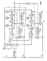
- FIG. 2 shows the application of the inventive method using the example of a speed control.
- the control variable y fed back to the input of the speed controller 3, which consists of the speed of the motor 5, is also superimposed on a measured value disturbance designated MST.
- MST measured value disturbance
- the first step of the method according to the invention requires the selection of a signal z 'which is dependent only on the disturbance variable z. Therefore, the input variable u of the actuator 4 is subtractively fed to a mixer via a first filter FI1 and the output variable of the control system consisting of the drive motor 5 is added to this mixer M via a second filter FI2. As already mentioned in connection with the principle of operation according to FIG. 1, the two filters FI1 and FI2 must be dimensioned such that the input variable u of the actuator 4 at the output of the mixing element M is unable to produce any effect, so that only one of the disturbance variables z dependent signal z 'occurs.
- the transfer function F1 of the first filter FI1 must be equal to the product of the transfer function F2 of the second filter FI2 and the transfer function F a .
- F b must be dimensioned from the input variable u to the output variable of the controlled system 5. It is free to choose the transfer function F2 of the filter FI1 and can adapt it to the respective requirements.
- the counter of the transfer function F2 therefore receives the form s. T ⁇ M , where the motor time constant T M of the drive motor 5 is to be simulated with the coefficient T ⁇ M. So that the transfer function F2 can be realized, it is necessary that the order of its denominator polynomial N F2 (s) is at least one degree larger than the order of its numerator.
- the correction element K consists of a disturbance variable observer containing three integrators 6, 7 and 8 and two function generators designated FG1 and FG2, with which an amplitude weighting of the sine or Cosine-shaped output signals of the disturbance variable observer for frequency-selective implementation of the correction frequency response F K is carried out.
- the disturbance variable observer consisting of the integrators 6 to 8
- the selective variable z 'supplied to the correction element K is to be reproduced completely, ie both with regard to its direct component z0 and also with regard to its alternating component z1.
- This simulated signal is denoted by ⁇ '.
- the integrator 6 emulating the direct component of the selected signal z 'and the two other integrators 7 and 8 arranged in series and fed back to an oscillation element are in a manner known per se from the error signal e, ie the difference between the supplied signal z' and the simulated signal ⁇ ' in accordance with the coefficients h0, h1 and h2 so that there is agreement between the signal z 'and its replica ⁇ ' and the error signal e becomes zero.
- the frequency of the shrinkage element consisting of the integrators 7 and 8 is determined by the quantity ⁇ supplied to the integrators 7 and 8 multiplicatively, which can be selected either proportional to the actual value of the controlled variable, namely the speed y of the motor 5 or proportional to the speed setpoint y *.
- an alternating component of the selected variable z ′ simulates a sinusoidal signal ⁇ ′ sin ( ⁇ t + ⁇ ′), which adds to the direct component of the selected signal z ′ simulated by the integrator 6, the latter Signal simulated size ⁇ 'results.
- a signal of the form ⁇ ′cos ( ⁇ t + ⁇ ′) which leads the phase of the selected variable z ′ by 90 ° arises.
- the output signals of the integrators 7 and 8 are now amplitude-weighted to implement the correction frequency response F K (j ⁇ ) required for the compensation with the output signals of function generators FG1 and FG2 controlled with the frequency ⁇ , which is done using two multipliers 11 and 12, respectively.
- the function generators FG1 and FG2 can be analog arithmetic circuits; With the current state of the art, these can also be implemented with commercially available digital signal processors, for example with the TMS320xx signal processor from Texas Instruments.
- the output signals of the multipliers 11 and 12 are added and the resulting sum signal z " 1 , which corresponds to the frequency response-corrected alternating component of the selected signal z ', a corresponding direct component derived from the output signal of the integrator 6 is also z " 0 added, with which the signal z ⁇ required for the feedforward control is then obtained.
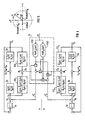
- Figure 3 shows an embodiment of the correction element K, with which, in addition to the fundamental component of the selected variable z ', a further, higher harmonic harmonic can be reproduced from their frequency spectrum and made available accordingly corrected.
- the disturbance variable observer is accordingly expanded by an additional integrator pair 7 ', 8', which is tracked by the error signal e in the same way as the original integrator pair 7, 8 and is pre-controlled with the n-fold frequency n . ⁇ instead of the frequency ⁇ .
- the function and mode of operation of the two function generators FG1 n and FG2 n are the same as for the function generators FG1 and FG2.
- the only difference is that the functions n to be formed by them have the variable n . ⁇ instead of the variable ⁇ , since the real and imaginary part of the complex frequency response F K (jn. ⁇ ) must now be provided.
- FIG. 4 shows an application of the method according to the invention for the position control of an unbalanced, electromagnetically mounted rotor in two mutually perpendicular axes x and y.
- a control loop is provided for the control along each axis, consisting of the position controllers 3x and 3y, the actuators 4z and 4y and the control systems 5x and 5y.
- the periodic disturbance can be correspondingly arranged in two at right angles to one another Axes in the mixing elements M x and M y to z ' 1x and Z ' 1y be selected.
- the filters FI1 x and FI2 x or FI1 y and FI2 y are dimensioned in the manner previously described.
- the denominator polynomial N S (s) of the respective controlled systems 5x or 5y is compensated with the numerator polynomial of the transfer functions of the filters FI2 x or FI2 y .
- the denominators of these transfer functions contain, with the term Z F (s), a component with which the direct component of the interference components z 0x and z 0y occurring in the x and y directions is suppressed.
- These DC components can either be corrected using the position controllers 3x or 3y designed as PI controllers in the example in FIG. 4, or can be simulated by the observer in the case of a state control and applied from there to compensate.
- the cause of the disturbance variable is an imbalance that rotates with the angular frequency ⁇ , and in the two mutually perpendicular axes x and y, their mutually perpendicular components z 1x and z 1y are recorded by measurement or to the signals e.g. ' 1x or z ' 1y selected.
- the basic oscillation components required for the frequency response correction according to the invention, together with the signals that advance them by 90 ° in relation to the phase oscillation, are therefore already available, because the mixing element M y or M assigned to the other axis supplies the basic oscillation component at the output of the one mixing element M x or M y x the vibration component leading the phase by 90 °.
- the selected signals z ' 1x and Z ' 1y not to compensate for disturbance variables in front of the point of attack of the disturbance variable, but to suppress disturbance variables in the output variable Y x or Y y of the controlled system 5x or 5y, as corresponds to the version shown in dashed lines in the basic block diagram in FIG.
- F K (j ⁇ ) N F (j ⁇ ) / (N ⁇ S (j ⁇ ).
- Z F (j ⁇ )) form.
- Figure 6 shows a position control for the employment in a schematically illustrated roll stand 13.
- This consists of an upper support roller with the radius R0, a lower support roller with the radius R u , the two smaller-diameter work rolls, a hydraulic piston effecting the adjustment of the upper support roller and an associated hydraulic cylinder, which is supported on the scaffold frame.
- the elastic frame is symbolically represented by a spring with the spring constant C G.
- the rolling stock to which an equivalent material spring with the spring constant C M is assigned in the roll gap, is rolled down from the inlet thickness h e to the outlet thickness h a by means of the two work rolls.
- the roller eccentricity of the upper or lower backup roller is caused by uneven roller wear, deformations due to thermal stresses and deviations in the geometric Cylinder axes of the rollers from the rotational axes that arise during operation. They are denoted by ⁇ R0 or ⁇ R u , that is, as deviations from the ideal supporting roller half-diameters R0 or R u .
- the sum of the influences of these deviations can be referred to as the (total) roll eccentricity ⁇ R and represents a periodically acting disturbance variable z.
- Measuring transducers are provided for the backup roll speed ⁇ , usually in the form of a tachodynamo coupled to the drive motor, for the rolling force WK exerted by the hydraulic piston and for the roller position, which corresponds to the relative position S of the hydraulic piston adjusting the upper support roller.
- a control element is designated, by means of which the hydraulic piston is acted upon by a valve with pressure oil.
- the control signal for the control element 14 consists in the output signal of a position controller 15, the setpoint of which is the signal S *.
- FIG. 6 shows the retrofitting of the known roller eccentricity compensator according to the invention for the exact elimination of the influence of roller eccentricities for the cases in which these conditions do not exist.
- this consists in that the output signals of the integrator pairs 17, 18 and 19, 20 which model the roller eccentricity ⁇ R are fed to multipliers 21, 22, 23, 24 and the second inputs of these multipliers of frequency-controlled function generators FG1 , FG2 for the real and imaginary part of the correction frequency response are applied.
- the sum of the output signals of the multipliers is then applied to the setpoint S * of the position controller 15.
- the roller eccentricity compensator 16 is acted upon by the output signals of two filters FI1 and FI2.
- the filter FI2 is a smoothing filter for the measured value of the rolling force WK with the transfer function F m .
- the input variable of the position control loop is via the filter FI1 with the transfer function F ⁇ s .
- F m led, where F ⁇ s F ⁇ R. F ⁇ ST / (1 + F ⁇ R. F ⁇ ST ) is the simulated transfer function of the position control loop, where F ⁇ R and F ⁇ ST are the simulated transfer functions of position controller 15 or actuator 14.
- This variable z ' is then simulated in a known manner by the disturbance variable observer consisting of the integrators 17, 18 and 19.20 and by means of the function generators FG1 and FG2 and the multipliers 20 to 23 in the manner already described the correction frequency response subject to frequency selectivity.
- the output variable z ⁇ is then applied to the setpoint S * of the position control loop in a manner that compensates for the disturbance variable z.
Landscapes
- Engineering & Computer Science (AREA)
- General Engineering & Computer Science (AREA)
- Mechanical Engineering (AREA)
- Physics & Mathematics (AREA)
- Electromagnetism (AREA)
- Feedback Control In General (AREA)
- Stereo-Broadcasting Methods (AREA)
- Control Of Electric Motors In General (AREA)
- Measurement Of Mechanical Vibrations Or Ultrasonic Waves (AREA)
Priority Applications (6)
| Application Number | Priority Date | Filing Date | Title |
|---|---|---|---|
| AT89112580T ATE97471T1 (de) | 1989-07-10 | 1989-07-10 | Verfahren und einrichtung zur elimination des einflusses von periodischen stoergroessen mit bekannter, veraenderlicher frequenz. |
| EP89112580A EP0407628B1 (fr) | 1989-07-10 | 1989-07-10 | Procédé et installation pour l'élimination de grandeurs périodiques perturbatrices ayant des fréquences connues et variables |
| DE89112580T DE58906215D1 (de) | 1989-07-10 | 1989-07-10 | Verfahren und Einrichtung zur Elimination des Einflusses von periodischen Störgrössen mit bekannter, veränderlicher Frequenz. |
| JP2179368A JPH0346004A (ja) | 1989-07-10 | 1990-07-06 | 周期的擾乱の影響の消去方法および装置 |
| CA002020661A CA2020661C (fr) | 1989-07-10 | 1990-07-06 | Methode et dispositif pour eliminer l'effet de variables perturbatrices periodiques a frequence variable connue |
| US07/549,358 US5036265A (en) | 1989-07-10 | 1990-07-06 | Method and device for eliminating the effect of periodic disturbance variable having a known, variable frequency |
Applications Claiming Priority (1)
| Application Number | Priority Date | Filing Date | Title |
|---|---|---|---|
| EP89112580A EP0407628B1 (fr) | 1989-07-10 | 1989-07-10 | Procédé et installation pour l'élimination de grandeurs périodiques perturbatrices ayant des fréquences connues et variables |
Publications (2)
| Publication Number | Publication Date |
|---|---|
| EP0407628A1 true EP0407628A1 (fr) | 1991-01-16 |
| EP0407628B1 EP0407628B1 (fr) | 1993-11-18 |
Family
ID=8201604
Family Applications (1)
| Application Number | Title | Priority Date | Filing Date |
|---|---|---|---|
| EP89112580A Expired - Lifetime EP0407628B1 (fr) | 1989-07-10 | 1989-07-10 | Procédé et installation pour l'élimination de grandeurs périodiques perturbatrices ayant des fréquences connues et variables |
Country Status (6)
| Country | Link |
|---|---|
| US (1) | US5036265A (fr) |
| EP (1) | EP0407628B1 (fr) |
| JP (1) | JPH0346004A (fr) |
| AT (1) | ATE97471T1 (fr) |
| CA (1) | CA2020661C (fr) |
| DE (1) | DE58906215D1 (fr) |
Cited By (3)
| Publication number | Priority date | Publication date | Assignee | Title |
|---|---|---|---|---|
| EP0424709A3 (en) * | 1989-10-25 | 1992-12-02 | Sms Schloemann-Siemag Aktiengesellschaft | Method for compensating failures due to roll eccentricity |
| WO2001033304A3 (fr) * | 1999-10-31 | 2001-11-15 | Eugen Saffert | Systeme de regulation pour organes de commande electriques et procede de regulation de trajectoire |
| EP4613393A1 (fr) | 2024-03-06 | 2025-09-10 | Primetals Technologies Germany GmbH | Cage de laminoir avec compensation complète d'excentricités |
Families Citing this family (11)
| Publication number | Priority date | Publication date | Assignee | Title |
|---|---|---|---|---|
| ATE128652T1 (de) * | 1992-02-24 | 1995-10-15 | Siemens Ag | Regelung mit vorsteuerung, insbesondere für ein walzgerüst. |
| JP3319030B2 (ja) * | 1993-05-18 | 2002-08-26 | 株式会社日立製作所 | 磁気軸受の制御装置およびそれを用いた回転機械 |
| EP0698427B1 (fr) * | 1994-07-28 | 1997-12-03 | Siemens Aktiengesellschaft | Procédé pour supprimer l'influence des excentricités de rouleaux de laminage |
| US5736801A (en) * | 1995-08-18 | 1998-04-07 | Ebara Corporation | Filter circuit and control circuit for controlling a rotor |
| GB2374683B (en) * | 2000-11-01 | 2004-08-11 | Mitsubishi Electric Corp | Servo control apparatus |
| DE10300543B4 (de) * | 2003-01-09 | 2005-01-13 | Siemens Ag | Verfahren zur Streckenidentifikation einer Regelstrecke |
| JP4481137B2 (ja) * | 2003-11-13 | 2010-06-16 | アスモ株式会社 | モータ、回転制御装置、及び回転検出回路 |
| JP4997139B2 (ja) * | 2008-02-21 | 2012-08-08 | アズビル株式会社 | モデリング装置 |
| GB201001007D0 (en) * | 2010-01-22 | 2010-03-10 | Ulive Entpr Ltd | Apparatus and method for measuring a phasor of an electrical power system signal |
| FR2995646B1 (fr) * | 2012-09-17 | 2014-08-29 | Ge Energy Power Conversion Technology Ltd | Dispositif et procede de commande d'un palier magnetique actif |
| CN111894979B (zh) * | 2020-07-29 | 2022-07-26 | 南京邮电大学 | 一种具有容错功能的多桥臂开关功放电路 |
Citations (4)
| Publication number | Priority date | Publication date | Assignee | Title |
|---|---|---|---|---|
| FR2336603A1 (fr) * | 1975-12-24 | 1977-07-22 | Europ Propulsion | Dispositif d'amortissement des frequences critiques d'un rotor suspendu magnetiquement |
| DE3120691A1 (de) * | 1981-05-23 | 1982-12-16 | Teldix Gmbh, 6900 Heidelberg | Magnetlager |
| GB2129582A (en) * | 1982-11-11 | 1984-05-16 | Seiko Instr & Electronics | Controlled magnetic bearing device |
| EP0170016B1 (fr) * | 1984-07-05 | 1988-12-07 | Siemens Aktiengesellschaft | Méthode pour compenser l'influence de l'excentricité de rouleaux de laminage |
Family Cites Families (3)
| Publication number | Priority date | Publication date | Assignee | Title |
|---|---|---|---|---|
| US4500823A (en) * | 1983-02-25 | 1985-02-19 | Westinghouse Electric Corp. | Electro-optical tracking system with adaptive bearing friction compensation |
| JPS61243505A (ja) * | 1985-04-19 | 1986-10-29 | Omron Tateisi Electronics Co | 離散時間制御装置 |
| JPH01248211A (ja) * | 1988-03-29 | 1989-10-03 | Teijin Seiki Co Ltd | 安定性補償回路 |
-
1989
- 1989-07-10 DE DE89112580T patent/DE58906215D1/de not_active Expired - Fee Related
- 1989-07-10 EP EP89112580A patent/EP0407628B1/fr not_active Expired - Lifetime
- 1989-07-10 AT AT89112580T patent/ATE97471T1/de not_active IP Right Cessation
-
1990
- 1990-07-06 JP JP2179368A patent/JPH0346004A/ja active Pending
- 1990-07-06 CA CA002020661A patent/CA2020661C/fr not_active Expired - Lifetime
- 1990-07-06 US US07/549,358 patent/US5036265A/en not_active Expired - Lifetime
Patent Citations (4)
| Publication number | Priority date | Publication date | Assignee | Title |
|---|---|---|---|---|
| FR2336603A1 (fr) * | 1975-12-24 | 1977-07-22 | Europ Propulsion | Dispositif d'amortissement des frequences critiques d'un rotor suspendu magnetiquement |
| DE3120691A1 (de) * | 1981-05-23 | 1982-12-16 | Teldix Gmbh, 6900 Heidelberg | Magnetlager |
| GB2129582A (en) * | 1982-11-11 | 1984-05-16 | Seiko Instr & Electronics | Controlled magnetic bearing device |
| EP0170016B1 (fr) * | 1984-07-05 | 1988-12-07 | Siemens Aktiengesellschaft | Méthode pour compenser l'influence de l'excentricité de rouleaux de laminage |
Cited By (4)
| Publication number | Priority date | Publication date | Assignee | Title |
|---|---|---|---|---|
| EP0424709A3 (en) * | 1989-10-25 | 1992-12-02 | Sms Schloemann-Siemag Aktiengesellschaft | Method for compensating failures due to roll eccentricity |
| WO2001033304A3 (fr) * | 1999-10-31 | 2001-11-15 | Eugen Saffert | Systeme de regulation pour organes de commande electriques et procede de regulation de trajectoire |
| EP4613393A1 (fr) | 2024-03-06 | 2025-09-10 | Primetals Technologies Germany GmbH | Cage de laminoir avec compensation complète d'excentricités |
| WO2025186051A1 (fr) | 2024-03-06 | 2025-09-12 | Primetals Technologies Germany Gmbh | Support de rouleau à compensation complète d'excentricités |
Also Published As
| Publication number | Publication date |
|---|---|
| JPH0346004A (ja) | 1991-02-27 |
| DE58906215D1 (de) | 1993-12-23 |
| CA2020661C (fr) | 2000-10-17 |
| EP0407628B1 (fr) | 1993-11-18 |
| ATE97471T1 (de) | 1993-12-15 |
| US5036265A (en) | 1991-07-30 |
| CA2020661A1 (fr) | 1991-01-11 |
Similar Documents
| Publication | Publication Date | Title |
|---|---|---|
| EP0407628B1 (fr) | Procédé et installation pour l'élimination de grandeurs périodiques perturbatrices ayant des fréquences connues et variables | |
| EP0170016B1 (fr) | Méthode pour compenser l'influence de l'excentricité de rouleaux de laminage | |
| DE10012280B4 (de) | Steuervorrichtung für einen Induktionsmotor | |
| DE10085353B4 (de) | Servosteuervorrichtung | |
| DE112006001287B4 (de) | Elektromotor-Steuervorrichtung | |
| EP1202147B1 (fr) | Procédé pour compenser des vibrations mécaniques dans des machines | |
| EP3732456B1 (fr) | Procédé pour l'estimation d'un couple effectif interne d'un générateur de couple | |
| DE3423656A1 (de) | Verfahren und vorrichtung zum erzeugen eines signals zur exzentrizitaetskompensation zur mass- oder lagesteuerung in einem walzgeruest einer walzstrasse o. dgl. | |
| DE10149525A1 (de) | Verfahren zur Kompensation mechanischer Schwingungen in Maschinen | |
| WO1997008820A1 (fr) | Procede et dispositif de correction de la direction de flux d'un modele de flux d'un moteur a champ rotatif, commande sans capteur et par orientation de champ jusqu'a une frequence zero | |
| DE102016014560A1 (de) | Lenkungssteuerungsvorrichtung und lenkungssteuerungsverfahren | |
| EP3329335A1 (fr) | Atténuation d'oscillations de charge sans moyens de mesure supplémentaires du côté de la charge | |
| EP0684090B1 (fr) | Procédé pour la suppression d'influence d'excentricité de cylindre sur le réglage d'épaisseur de matières à laminer dans une cage de laminoir | |
| DE112020006880T5 (de) | Steuereinrichtung | |
| DE2621430C2 (de) | Kompensationssystem für eine numerisch gesteuerte Werkzeugmaschine | |
| EP1118043B1 (fr) | Procede et circuit pour parametrer automatiquement un circuit de regulation de vitesse numerique rapide | |
| EP3664282B1 (fr) | Compensation des couple de détente des moteurs synchrones | |
| DE3816484C2 (fr) | ||
| EP0937331B1 (fr) | Procede et dispositif permettant de determiner le nombre de tours d'une machine polyphasee exempte de capteur et fonctionnant avec orientation du champ | |
| DE2440166C2 (de) | Vorrichtung zur Dickenregelung von Walzband | |
| EP0698427B1 (fr) | Procédé pour supprimer l'influence des excentricités de rouleaux de laminage | |
| EP0739500B1 (fr) | Procede de regulation | |
| DE2605183A1 (de) | Einrichtung zur regelung der dicke des walzgutes in einem walzwerk | |
| DE69622010T2 (de) | Verfahren zur Spindeldrehzahloptimierung für ein Bewegungsprofil | |
| DE4410960B4 (de) | Verfahren zur Unterdrückung des Einflusses von Walzenexzentrizitäten |
Legal Events
| Date | Code | Title | Description |
|---|---|---|---|
| PUAI | Public reference made under article 153(3) epc to a published international application that has entered the european phase |
Free format text: ORIGINAL CODE: 0009012 |
|
| AK | Designated contracting states |
Kind code of ref document: A1 Designated state(s): AT BE CH DE FR GB LI NL SE |
|
| 17P | Request for examination filed |
Effective date: 19901205 |
|
| 17Q | First examination report despatched |
Effective date: 19920708 |
|
| GRAA | (expected) grant |
Free format text: ORIGINAL CODE: 0009210 |
|
| AK | Designated contracting states |
Kind code of ref document: B1 Designated state(s): AT BE CH DE FR GB LI NL SE |
|
| REF | Corresponds to: |
Ref document number: 97471 Country of ref document: AT Date of ref document: 19931215 Kind code of ref document: T |
|
| REF | Corresponds to: |
Ref document number: 58906215 Country of ref document: DE Date of ref document: 19931223 |
|
| ET | Fr: translation filed | ||
| GBT | Gb: translation of ep patent filed (gb section 77(6)(a)/1977) |
Effective date: 19940225 |
|
| PLBE | No opposition filed within time limit |
Free format text: ORIGINAL CODE: 0009261 |
|
| STAA | Information on the status of an ep patent application or granted ep patent |
Free format text: STATUS: NO OPPOSITION FILED WITHIN TIME LIMIT |
|
| 26N | No opposition filed | ||
| EAL | Se: european patent in force in sweden |
Ref document number: 89112580.9 |
|
| PGFP | Annual fee paid to national office [announced via postgrant information from national office to epo] |
Ref country code: GB Payment date: 19980623 Year of fee payment: 10 |
|
| PGFP | Annual fee paid to national office [announced via postgrant information from national office to epo] |
Ref country code: AT Payment date: 19980707 Year of fee payment: 10 |
|
| PGFP | Annual fee paid to national office [announced via postgrant information from national office to epo] |
Ref country code: BE Payment date: 19980709 Year of fee payment: 10 |
|
| PGFP | Annual fee paid to national office [announced via postgrant information from national office to epo] |
Ref country code: SE Payment date: 19980717 Year of fee payment: 10 |
|
| PGFP | Annual fee paid to national office [announced via postgrant information from national office to epo] |
Ref country code: NL Payment date: 19980728 Year of fee payment: 10 |
|
| PGFP | Annual fee paid to national office [announced via postgrant information from national office to epo] |
Ref country code: FR Payment date: 19980729 Year of fee payment: 10 |
|
| PGFP | Annual fee paid to national office [announced via postgrant information from national office to epo] |
Ref country code: DE Payment date: 19980917 Year of fee payment: 10 |
|
| PGFP | Annual fee paid to national office [announced via postgrant information from national office to epo] |
Ref country code: CH Payment date: 19981102 Year of fee payment: 10 |
|
| PG25 | Lapsed in a contracting state [announced via postgrant information from national office to epo] |
Ref country code: GB Free format text: LAPSE BECAUSE OF NON-PAYMENT OF DUE FEES Effective date: 19990710 Ref country code: AT Free format text: LAPSE BECAUSE OF NON-PAYMENT OF DUE FEES Effective date: 19990710 |
|
| PG25 | Lapsed in a contracting state [announced via postgrant information from national office to epo] |
Ref country code: SE Free format text: THE PATENT HAS BEEN ANNULLED BY A DECISION OF A NATIONAL AUTHORITY Effective date: 19990711 |
|
| PG25 | Lapsed in a contracting state [announced via postgrant information from national office to epo] |
Ref country code: LI Free format text: LAPSE BECAUSE OF NON-PAYMENT OF DUE FEES Effective date: 19990731 Ref country code: FR Free format text: THE PATENT HAS BEEN ANNULLED BY A DECISION OF A NATIONAL AUTHORITY Effective date: 19990731 Ref country code: CH Free format text: LAPSE BECAUSE OF NON-PAYMENT OF DUE FEES Effective date: 19990731 Ref country code: BE Free format text: LAPSE BECAUSE OF NON-PAYMENT OF DUE FEES Effective date: 19990731 |
|
| BERE | Be: lapsed |
Owner name: SIEMENS A.G. Effective date: 19990731 |
|
| PG25 | Lapsed in a contracting state [announced via postgrant information from national office to epo] |
Ref country code: NL Free format text: LAPSE BECAUSE OF NON-PAYMENT OF DUE FEES Effective date: 20000201 |
|
| GBPC | Gb: european patent ceased through non-payment of renewal fee |
Effective date: 19990710 |
|
| REG | Reference to a national code |
Ref country code: CH Ref legal event code: PL |
|
| EUG | Se: european patent has lapsed |
Ref document number: 89112580.9 |
|
| NLV4 | Nl: lapsed or anulled due to non-payment of the annual fee |
Effective date: 20000201 |
|
| PG25 | Lapsed in a contracting state [announced via postgrant information from national office to epo] |
Ref country code: DE Free format text: LAPSE BECAUSE OF NON-PAYMENT OF DUE FEES Effective date: 20000503 |
|
| REG | Reference to a national code |
Ref country code: FR Ref legal event code: ST |