EP0407724A1 - Semoir monograine - Google Patents
Semoir monograine Download PDFInfo
- Publication number
- EP0407724A1 EP0407724A1 EP90110426A EP90110426A EP0407724A1 EP 0407724 A1 EP0407724 A1 EP 0407724A1 EP 90110426 A EP90110426 A EP 90110426A EP 90110426 A EP90110426 A EP 90110426A EP 0407724 A1 EP0407724 A1 EP 0407724A1
- Authority
- EP
- European Patent Office
- Prior art keywords
- elements
- precision
- precision sowing
- soil
- harrow
- Prior art date
- Legal status (The legal status is an assumption and is not a legal conclusion. Google has not performed a legal analysis and makes no representation as to the accuracy of the status listed.)
- Granted
Links
Images

Classifications
-
- A—HUMAN NECESSITIES
- A01—AGRICULTURE; FORESTRY; ANIMAL HUSBANDRY; HUNTING; TRAPPING; FISHING
- A01B—SOIL WORKING IN AGRICULTURE OR FORESTRY; PARTS, DETAILS, OR ACCESSORIES OF AGRICULTURAL MACHINES OR IMPLEMENTS, IN GENERAL
- A01B37/00—Devices for loosening soil compacted by wheels or the like
-
- A—HUMAN NECESSITIES
- A01—AGRICULTURE; FORESTRY; ANIMAL HUSBANDRY; HUNTING; TRAPPING; FISHING
- A01C—PLANTING; SOWING; FERTILISING
- A01C5/00—Making or covering furrows or holes for sowing, planting or manuring
- A01C5/06—Machines for making or covering drills or furrows for sowing or planting
- A01C5/066—Devices for covering drills or furrows
-
- A—HUMAN NECESSITIES
- A01—AGRICULTURE; FORESTRY; ANIMAL HUSBANDRY; HUNTING; TRAPPING; FISHING
- A01C—PLANTING; SOWING; FERTILISING
- A01C7/00—Sowing
- A01C7/04—Single-grain seeders with or without suction devices
-
- Y—GENERAL TAGGING OF NEW TECHNOLOGICAL DEVELOPMENTS; GENERAL TAGGING OF CROSS-SECTIONAL TECHNOLOGIES SPANNING OVER SEVERAL SECTIONS OF THE IPC; TECHNICAL SUBJECTS COVERED BY FORMER USPC CROSS-REFERENCE ART COLLECTIONS [XRACs] AND DIGESTS
- Y02—TECHNOLOGIES OR APPLICATIONS FOR MITIGATION OR ADAPTATION AGAINST CLIMATE CHANGE
- Y02A—TECHNOLOGIES FOR ADAPTATION TO CLIMATE CHANGE
- Y02A40/00—Adaptation technologies in agriculture, forestry, livestock or agroalimentary production
- Y02A40/10—Adaptation technologies in agriculture, forestry, livestock or agroalimentary production in agriculture
- Y02A40/22—Improving land use; Improving water use or availability; Controlling erosion
Definitions
- the invention relates to a precision sowing device with several precision sowing units arranged next to one another on a frame at a distance from one another.
- Precision sowing machines of this type have been known in agricultural practice for a long time.
- the single-grain sowing units arranged side by side on the frame of the single-grain sowing machine each have a seed separating device, so that the seed to be sown in each case is deposited in the soil within a row of seeds at a specific, adjustable distance between the individual seeds.
- the preparation of the soil before the use of the precision seed drill, ie the seed bed can be carried out in a variety of ways by using a wide variety of tillage equipment.
- the most common way of preparing the seedbed consists of full-surface tillage, whereby the entire soil surface of the field to be cultivated is worked, although the seeds are deposited in large rows, for example 75 cm for maize.
- Rotary driven soil tillage implements with a downstream trailing roller for reconsolidation of the cultivated soil are very often used for seedbed preparation, these soil tillage implements being used for plowed as well as plowed fields.
- the reconsolidation of the soil bear Soil processed tillage device also takes place over the entire surface or in strips from the trailing roller arranged behind the tillage device. A good reconsolidation of the cultivated soil forms the basis for a proper emergence of the seeds deposited in the soil.
- the relatively smooth soil surface that arises during reconsolidation of the cultivated soil during seedbed preparation has a disadvantageous effect when sowing seeds with a large row spacing by means of the precision seed drills, since there is a risk of erosion or removal of soil parts between the individual seed rows, particularly on soils that are at risk of erosion .
- This washing away or carrying away the soil parts is favored by the solidified areas, especially between the individual rows of seeds, because the soil surface between the rows is relatively smooth and offers a good surface for the wind or rainwater, so that soil erosion can occur.
- the object of the invention is now to counteract soil erosion with the simplest of means when using precision seed drills on soils that are at risk of erosion.
- soil loosening elements such as for example weeder elements etc. are arranged in the area between the precision sowing units between them or behind them.
- the harrow elements are designed as so-called exact harrow elements with spreading elements which are inclined to the direction of travel and run essentially parallel to the soil surface.
- the harrow elements are designed as upright elements which engage with their free ends in the ground.
- the harrow elements are only arranged behind the sowing units of the precision seed drill when viewed in the direction of travel.
- the harrow elements are arranged directly on the frame of the precision sowing units. This results in a simple arrangement of the harrow elements.
- a bar running transversely to the direction of travel is arranged behind the precision seed drill and that the harrow elements are fastened to this bar.
- this embodiment according to the invention provides that the beam with the harrow elements can be pivoted forwardly in the direction of travel by means of a lifting device, so as to shift the overall center of gravity for lifting and transporting the machine in the direction of the three-point coupling elements. This achieves a more favorable weight distribution of the machine to be lifted, which extends far behind the agricultural tractor transporting the precision seed drill.
- the lifting device for pivoting the beam forward is switched in such a way that the beam is pivoted forwards at the same time as the planter is lifted out and the beam is pivoted backwards when the planter is lowered.
- the beam automatically swivels forward, which also reduces the backward length of the precision seed drill, which has a particularly favorable effect on turning maneuvers on the headlands.
- the bar is then automatically swung back again.
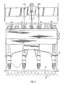
- the first figure 1 shows a combination of implements consisting of the driven tillage implement 1, the trailing roller 2 with the compression elements 3 arranged next to one another, designed as tires, the fertilizer spreading device 5, which is mounted on the trailing roller 2 and has the fertilizer hopper 4, and the precision seed drill 6 with its precision sowing units arranged side by side 7.
- the implement combination is coupled in a known and therefore not shown manner to the three-point linkage of an agricultural tractor, the implement combination then being pulled in the direction of travel 8 during use over the arable area to be worked and to be ordered.
- the soil tillage implement 1 By means of the soil tillage implement 1, the seed bed is prepared and the one next to the other arranged compacting elements 3 having trailing roller 2 reconsolidated.
- the trailing roller 2 is designed in such a way that the strip-shaped compacting elements 3 are aligned with the coulters of the precision sowing units 7 and in the spaces 9 of the precision sowing units 7 arranged next to one another.
- the compaction elements 3 of the trailing roller 2 take over the reconsolidation of the soil processed by the tillage implement 1, so that the seed deposited in the soil by the coulters of the precision seeding units 7 finds optimal growth conditions. Since the compacting elements 3 arranged in the spaces 9 between the individual single-grain sowing units 7 now carry out such a strip-like soil compaction in this area, the soil loosening elements 11 located between the single-grain sowing units 7 on a support frame 10 are fastened in order to level this strip-type soil compaction. These loosening elements 11 are designed as harrow elements. These harrow elements 11 provide leveling, i.e.
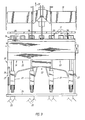
- the device combination according to FIG. 2 differs from the device combination according to FIG. 1 only by a different arrangement of the soil loosening elements 12.
- the soil loosening elements 12 are located behind the precision sowing units 7, whereby the soil loosening elements 12 are arranged over the entire area behind the single grain sowing units 7, ie that she also level the areas immediately behind the single-grain sowing units 7.
- these soil loosening elements 12 are arranged on the frame 13 in such a way that they only process the area between the individual single-grain sowing units 7.
- the soil loosening elements 12 are fastened to the frame 13 in an adjustable manner at different distances from one another, so that they can be individually adjusted precisely to these row distances in the case of different row distances of the precision sowing units arranged next to one another. So that the overall length of the implement combination can now be reduced during the transport trip, the frame 13 is pivoted about the pivot axis 14 to the frame of the trailing roller 2 or to the fertilizer reservoir 4.
- the device combination according to FIG. 3 consists of the driven tillage device 15, the trailing roller 16 with the compression elements 17 arranged next to one another, designed as tires, the fertilizer spreading device 19, which is mounted on the trailing roller 16 and has the fertilizer hopper 18, and the precision seed drill 20 with its precision sowing units 21 arranged next to one another .
- the implement combination is coupled in a known and therefore not shown manner to the three-point linkage of an agricultural tractor, the implement combination then being pulled in the direction of travel 22 over the arable area to be worked and to be cultivated during use.
- the seed bed is now prepared and reconsolidated by the trailing roller 16 which has the compaction elements 17 arranged next to one another.
- the trailing roller 16 is designed such that the strip-shaped compaction elements 17 are arranged in alignment with the coulters of the precision seed sowing units 21.
- the compaction elements 17 of the trailing roller 16 take over the reconsolidation of the soil processed by the tillage implement 15, so that the seed deposited in the soil by the coulters of the precision sowing units 21 finds optimal growth conditions.
- the compacting elements 17 arranged in the spaces 23 between the individual single-grain saw units 21 likewise perform a strip-shaped soil compaction in this area.
- the harrow elements 25 arranged on the beam 24 are arranged immediately behind the precision seed drill units.
- harrow elements 25 provide a leveling, ie, a closing of the compaction strips produced by the compaction elements 17 of the trailing roller 16, whereby the surface is loosened and loose soil parts from the harrow elements 25 to the compaction strips and the sowing furrows produced by the respective seed coulters of the single-grain sowing units 21 are transported, so that there is a soil surface with a loose and crumbled soil structure behind the precision sowing units.
- the harrow elements 25 are fastened to the pivotable bar 24, which runs transversely to the direction of travel 22.
- This bar 24 can be pivoted forward about the pivot axis 27 by means of the lifting device designed as a hydraulic cylinder 26, so that the bar 24 with the harrow elements 25 is pivoted in the direction of the fertilizer container 18 of the fertilizer spreading device 19. This results in a reduction in the overall length and a shift in weight of the device combination.
Landscapes
- Life Sciences & Earth Sciences (AREA)
- Soil Sciences (AREA)
- Environmental Sciences (AREA)
- Engineering & Computer Science (AREA)
- Mechanical Engineering (AREA)
- Soil Working Implements (AREA)
Applications Claiming Priority (4)
| Application Number | Priority Date | Filing Date | Title |
|---|---|---|---|
| DE19893923222 DE3923222A1 (de) | 1989-07-14 | 1989-07-14 | Einzelkornsaegeraet |
| DE3923222 | 1989-07-14 | ||
| DE4013531 | 1990-04-27 | ||
| DE4013531A DE4013531A1 (de) | 1989-07-14 | 1990-04-27 | Einzelkornsaegeraet |
Publications (2)
| Publication Number | Publication Date |
|---|---|
| EP0407724A1 true EP0407724A1 (fr) | 1991-01-16 |
| EP0407724B1 EP0407724B1 (fr) | 1993-09-22 |
Family
ID=25882998
Family Applications (1)
| Application Number | Title | Priority Date | Filing Date |
|---|---|---|---|
| EP90110426A Expired - Lifetime EP0407724B1 (fr) | 1989-07-14 | 1990-06-01 | Semoir monograine |
Country Status (4)
| Country | Link |
|---|---|
| EP (1) | EP0407724B1 (fr) |
| CZ (1) | CZ278389B6 (fr) |
| DE (2) | DE4013531A1 (fr) |
| HU (1) | HUT60420A (fr) |
Cited By (2)
| Publication number | Priority date | Publication date | Assignee | Title |
|---|---|---|---|---|
| CN101424592B (zh) * | 2008-12-09 | 2010-06-02 | 哈尔滨工业大学 | 车轮测试土槽的犁松平整机构 |
| CN102686099A (zh) * | 2009-12-31 | 2012-09-19 | 先锋国际良种公司 | 自动化种子取样设备、方法和系统 |
Families Citing this family (2)
| Publication number | Priority date | Publication date | Assignee | Title |
|---|---|---|---|---|
| DE19918281C1 (de) * | 1999-04-22 | 2000-09-28 | Josef Katz Einrichtungshaus Gm | Hohlprofil für ein Profilsystem |
| CN109275380A (zh) * | 2018-10-19 | 2019-01-29 | 禹州森茂迷迭香生物科技有限公司 | 一种板蓝根播种装置 |
Citations (5)
| Publication number | Priority date | Publication date | Assignee | Title |
|---|---|---|---|---|
| FR1422731A (fr) * | 1965-01-27 | 1965-12-24 | élément semeur de précision ainsi que les semoirs pourvus de cet élément ou élément similaire | |
| FR1456882A (fr) * | 1965-09-15 | 1966-07-08 | Semoir monograine perfectionné | |
| DE3306804A1 (de) * | 1983-02-26 | 1984-08-30 | Amazonen-Werke H. Dreyer Gmbh & Co Kg, 4507 Hasbergen | Saemaschine |
| DE8525904U1 (de) * | 1985-09-11 | 1985-10-24 | H. Fähse & Co, 5160 Düren | Tragvorrichtung für Säaggregate von Einzelkornsämaschinen |
| EP0251053A2 (fr) * | 1986-06-28 | 1988-01-07 | Amazonen-Werke H. Dreyer GmbH & Co. KG | Semoir |
-
1990
- 1990-04-27 DE DE4013531A patent/DE4013531A1/de not_active Ceased
- 1990-06-01 DE DE90110426T patent/DE59002811D1/de not_active Expired - Fee Related
- 1990-06-01 EP EP90110426A patent/EP0407724B1/fr not_active Expired - Lifetime
- 1990-06-22 HU HU903954A patent/HUT60420A/hu unknown
- 1990-07-11 CZ CS903409A patent/CZ278389B6/cs unknown
Patent Citations (5)
| Publication number | Priority date | Publication date | Assignee | Title |
|---|---|---|---|---|
| FR1422731A (fr) * | 1965-01-27 | 1965-12-24 | élément semeur de précision ainsi que les semoirs pourvus de cet élément ou élément similaire | |
| FR1456882A (fr) * | 1965-09-15 | 1966-07-08 | Semoir monograine perfectionné | |
| DE3306804A1 (de) * | 1983-02-26 | 1984-08-30 | Amazonen-Werke H. Dreyer Gmbh & Co Kg, 4507 Hasbergen | Saemaschine |
| DE8525904U1 (de) * | 1985-09-11 | 1985-10-24 | H. Fähse & Co, 5160 Düren | Tragvorrichtung für Säaggregate von Einzelkornsämaschinen |
| EP0251053A2 (fr) * | 1986-06-28 | 1988-01-07 | Amazonen-Werke H. Dreyer GmbH & Co. KG | Semoir |
Cited By (3)
| Publication number | Priority date | Publication date | Assignee | Title |
|---|---|---|---|---|
| CN101424592B (zh) * | 2008-12-09 | 2010-06-02 | 哈尔滨工业大学 | 车轮测试土槽的犁松平整机构 |
| CN102686099A (zh) * | 2009-12-31 | 2012-09-19 | 先锋国际良种公司 | 自动化种子取样设备、方法和系统 |
| CN102686099B (zh) * | 2009-12-31 | 2014-09-10 | 先锋国际良种公司 | 自动化种子取样设备、方法和系统 |
Also Published As
| Publication number | Publication date |
|---|---|
| CS340990A3 (en) | 1992-02-19 |
| DE59002811D1 (de) | 1993-10-28 |
| EP0407724B1 (fr) | 1993-09-22 |
| CZ278389B6 (en) | 1993-12-15 |
| HUT60420A (en) | 1992-09-28 |
| HU903954D0 (en) | 1990-11-28 |
| DE4013531A1 (de) | 1991-10-31 |
Similar Documents
| Publication | Publication Date | Title |
|---|---|---|
| DE112006000110B4 (de) | Kombinierte landwirtschaftliche Maschine | |
| DE4123854A1 (de) | Geschlossene duengerverteil- und saekombination | |
| DE102010017631A1 (de) | Landwirtschaftliche Bestellkombination | |
| DE4007783C2 (de) | Saatbeetkombination | |
| EP0172358B1 (fr) | Machine combinée pour l'ameublissement du sol et la préparation d'un lit de semence | |
| WO1986005352A1 (fr) | Procede et dispositif de semailles et/ou de plantation de mais, de betteraves a sucre, d'haricots, de cereales et similaires | |
| DD235992A5 (de) | Arbeitsverfahren zur aufbereitung als ackerbodens sowie eine geraetekombination zur durchfuehrung des verfahrens | |
| DE68903856T3 (de) | Mechanisch angetriebenes Bodenbearbeitungsgerät. | |
| EP0193804B1 (fr) | Méthode de semis de plantes de culture | |
| EP0445582B1 (fr) | Machine pour travailler le sol | |
| DE69608661T2 (de) | Grubberdrillschar | |
| EP0407724A1 (fr) | Semoir monograine | |
| EP0327869B1 (fr) | Machine combinée de culture et de semis | |
| DE602004004342T2 (de) | Sämaschine mit einer Einstellvorrichtung | |
| EP0380020B1 (fr) | Rouleau | |
| DE4138633A1 (de) | Verstopfungs-ausraeumer zwischen den saescharen, vornehmlich stiefelsaescharen, von drillmaschinen bekannter bauarten | |
| EP0586950A2 (fr) | Semoir | |
| DE102020133573B3 (de) | Landwirtschaftliches Anbaugerät | |
| DE3923222A1 (de) | Einzelkornsaegeraet | |
| EP0216003A2 (fr) | Méthode et disposition d'outils pour le travail du sol, la préparation du lit de semence et l'enfouissement des semences | |
| LU102034B1 (de) | Säscharanordnung | |
| DE3716672A1 (de) | Einzelkornsaemaschine | |
| AT3991U1 (de) | Bodenbearbeitungsmaschine | |
| DE102022004202A1 (de) | Breitpflug | |
| DE9309222U1 (de) | Saatbeetkombination |
Legal Events
| Date | Code | Title | Description |
|---|---|---|---|
| PUAI | Public reference made under article 153(3) epc to a published international application that has entered the european phase |
Free format text: ORIGINAL CODE: 0009012 |
|
| AK | Designated contracting states |
Kind code of ref document: A1 Designated state(s): DE FR NL |
|
| 17P | Request for examination filed |
Effective date: 19901213 |
|
| 17Q | First examination report despatched |
Effective date: 19920320 |
|
| GRAA | (expected) grant |
Free format text: ORIGINAL CODE: 0009210 |
|
| AK | Designated contracting states |
Kind code of ref document: B1 Designated state(s): DE FR NL |
|
| ET | Fr: translation filed | ||
| REF | Corresponds to: |
Ref document number: 59002811 Country of ref document: DE Date of ref document: 19931028 |
|
| PLBE | No opposition filed within time limit |
Free format text: ORIGINAL CODE: 0009261 |
|
| STAA | Information on the status of an ep patent application or granted ep patent |
Free format text: STATUS: NO OPPOSITION FILED WITHIN TIME LIMIT |
|
| 26N | No opposition filed | ||
| PGFP | Annual fee paid to national office [announced via postgrant information from national office to epo] |
Ref country code: NL Payment date: 19960630 Year of fee payment: 7 |
|
| PG25 | Lapsed in a contracting state [announced via postgrant information from national office to epo] |
Ref country code: NL Effective date: 19980101 |
|
| NLV4 | Nl: lapsed or anulled due to non-payment of the annual fee |
Effective date: 19980101 |
|
| PGFP | Annual fee paid to national office [announced via postgrant information from national office to epo] |
Ref country code: FR Payment date: 20000629 Year of fee payment: 11 |
|
| PG25 | Lapsed in a contracting state [announced via postgrant information from national office to epo] |
Ref country code: FR Free format text: LAPSE BECAUSE OF NON-PAYMENT OF DUE FEES Effective date: 20020228 |
|
| PGFP | Annual fee paid to national office [announced via postgrant information from national office to epo] |
Ref country code: DE Payment date: 20020620 Year of fee payment: 13 |
|
| PG25 | Lapsed in a contracting state [announced via postgrant information from national office to epo] |
Ref country code: DE Free format text: LAPSE BECAUSE OF NON-PAYMENT OF DUE FEES Effective date: 20040101 |