EP0407793A2 - Amortisseur à friction - Google Patents
Amortisseur à friction Download PDFInfo
- Publication number
- EP0407793A2 EP0407793A2 EP90111953A EP90111953A EP0407793A2 EP 0407793 A2 EP0407793 A2 EP 0407793A2 EP 90111953 A EP90111953 A EP 90111953A EP 90111953 A EP90111953 A EP 90111953A EP 0407793 A2 EP0407793 A2 EP 0407793A2
- Authority
- EP
- European Patent Office
- Prior art keywords
- friction
- damper according
- housing
- friction damper
- grease
- Prior art date
- Legal status (The legal status is an assumption and is not a legal conclusion. Google has not performed a legal analysis and makes no representation as to the accuracy of the status listed.)
- Granted
Links
Images
Classifications
-
- F—MECHANICAL ENGINEERING; LIGHTING; HEATING; WEAPONS; BLASTING
- F16—ENGINEERING ELEMENTS AND UNITS; GENERAL MEASURES FOR PRODUCING AND MAINTAINING EFFECTIVE FUNCTIONING OF MACHINES OR INSTALLATIONS; THERMAL INSULATION IN GENERAL
- F16F—SPRINGS; SHOCK-ABSORBERS; MEANS FOR DAMPING VIBRATION
- F16F7/00—Vibration-dampers; Shock-absorbers
- F16F7/08—Vibration-dampers; Shock-absorbers with friction surfaces rectilinearly movable along each other
- F16F7/09—Vibration-dampers; Shock-absorbers with friction surfaces rectilinearly movable along each other in dampers of the cylinder-and-piston type
-
- D—TEXTILES; PAPER
- D06—TREATMENT OF TEXTILES OR THE LIKE; LAUNDERING; FLEXIBLE MATERIALS NOT OTHERWISE PROVIDED FOR
- D06F—LAUNDERING, DRYING, IRONING, PRESSING OR FOLDING TEXTILE ARTICLES
- D06F37/00—Details specific to washing machines covered by groups D06F21/00 - D06F25/00
- D06F37/20—Mountings, e.g. resilient mountings, for the rotary receptacle, motor, tub or casing; Preventing or damping vibrations
Definitions
- the invention relates to a friction damper, in particular for washing machines with a spin cycle, consisting of an essentially circular-cylindrical housing and a plunger which can be moved coaxially therein, with one end leading out of the housing and at the other end provided with an approximately cylindrical friction piston, the friction piston having at least one approximately circular-cylindrical support section and this radially projecting and axially unchangeable limiting counter-flanges, wherein on the support section and between the counter-flanges a friction surface made of elastically resilient material pressed against the inner wall of the housing is arranged, and a lubricating grease storage chamber on the friction piston is trained.
- friction dampers are known from DE-OS 36 04 286 (corresponds to U.S. patent 4,729,458). These lubricated friction dampers have proven themselves to a great extent in practice; in particular, they are used extensively in washing machines.
- the friction linings usually consist of cellular, foamed plastic, the cells of the plastic being impregnated with fat. It has been shown that under extreme loads, the friction changes from a lubricated to a dry friction after a long time, i.e. the friction damper heats up very much.
- grease chambers designed in the form of an annular groove have already been provided on the outside of the friction piston, in which a small supply of additional grease is provided. This measure also did not lead to a fundamental elimination of the problem.
- the invention is therefore based on the object of developing the friction damper of the generic type in such a way that a drop in damping due to the transition from a lubricated to a dry friction is excluded.
- the grease storage chamber is formed within the friction piston and is connected to the respective support section via at least one grease channel.
- a permanent re-impregnation of the friction linings can take place through the grease storage chamber provided according to the invention.
- the grease travels through the grease channels in small quantities to the friction linings and through them to the friction surface between the friction lining and the inner wall of the housing.
- the grease storage chamber is delimited by an insert body located in the friction piston, then on the one hand the grease chamber itself can be manufactured in a simple manner and, in particular, it can be assembled in a simple manner with a grease filling in the friction piston.
- the latter is also possible in a particularly simple manner if, on the one hand, the insert body bears against the end face of the plunger facing the interior of the housing, and on the other hand, if the insert body is elastically locked to the plunger by means of barb-like fastening webs which engage in recesses in the plunger.
- the insert body is sealed in the region of its end facing the interior of the plunger against the inner wall of the friction piston.
- the at least one grease channel has a diameter of about 1.0 to 1.5 mm, then it is ensured that the respective friction lining does not press into the respective grease channel, so that again the friction force between the friction lining and the inner wall of the housing is prevented from falling in this area.
- an extension piece is provided on the end of the tappet in the housing, which, together with the adjacent counter flange and the inner wall of the housing, delimits a grease collecting chamber, this prevents the grease from not adhering to the housing deposits the points that come into contact with the friction lining. In particular, the grease is prevented from entering the cavity of the tappet, where it would no longer be used for lubrication. Furthermore, there is a risk that grease that has entered the interior of the tappet will escape to the outside through openings formed in the tappet. Grease distributed on the inner wall of the housing when the plunger extends from the housing is collected again when the plunger is moved into the housing.
- the extension piece can be formed on the insert body.
- the friction lining consists of cellular foamed plastic, in particular at least partially open-cell foamed plastic, then on the one hand the lubricating grease travels through the friction lining.
- a kind of pumping action occurs in the friction lining due to the changing deformations of the friction lining during a work cycle, the also leads to a promotion of the grease through the friction lining.
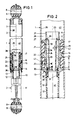
- the friction damper shown in the drawing has a housing 1 and a plunger 2.
- the housing 1 consists essentially of a cylindrical metallic tube 3, which is closed at one end by means of a base 4.
- an articulated sleeve 5 is attached for articulating the friction damper.
- This joint sleeve 5 has an axis of symmetry 6 serving as a pivot axis, which perpendicularly intersects the central longitudinal axis 7 of the friction damper.
- the plunger 2 also has an articulated bushing 8 at its outer end, the axis 9 of which likewise perpendicularly intersects the central longitudinal axis 7.
- the plunger 2 itself consists essentially of a tube 10 tapering towards the joint bushing 8, which is stiffened on its outside by means of longitudinal ribs 11.
- the tube 10 is provided with a vent opening 12.
- the plunger 2 is injection molded in one piece from plastic.
- a friction piston 13 is formed, which has annular counter spacing flanges 14, 15 and 16, 17 which are formed at a distance from one another and are assigned to one another in pairs.
- Circular-cylindrical support sections 18, 19 are formed between the mutually assigned counter-holding flanges 14, 15 and 16, 17, respectively, which are also arranged concentrically to the axis 7.
- a friction lining 20, 21 is arranged on each of the support sections 18, 19. These friction linings 20, 21 consist of a cellular, elastic foam, for example a polyurethane foam.
- annular groove-shaped grease chamber 22 which is relatively small in volume relative to the volume of a friction lining 20 or 21 is formed.
- a relatively large-volume grease storage chamber 23 is formed on the inside of the friction piston 13. This is delimited on its outside by the inner wall 24 of the friction piston 13 and on its inside and in the area of its axial ends by an insert body 25.
- This insert body 25 rests with an annular collar 26 on the end face 27 of the friction piston 13 and the region of the inner wall 24 adjacent thereto, so that it is fixed here on the one hand radially and on the other axially in the direction of the joint bushing 8 with respect to the friction piston 13.
- the insert body 25 At its other end, which faces the joint bushing 8, the insert body 25 has a cylinder section 28, in which an annular groove 29 is formed. In this there is an O-ring seal 30 which bears against the inner wall 24 of the friction piston 13, specifically in the area of the counter-holding flange 14 which is closest to the joint bushing 8.
- the storage chamber 23 thus extends approximately over the entire axial extent of the friction piston 13.
- the cylinder section 28 is followed by two fastening webs 31, each of which has a barb-like, radially outwardly projecting projection 32, which engages in a corresponding recess 33 in the tube 10 of the plunger 2 in the assembled state of the insert body 25.
- the fastening webs 31 are designed such that they are elastically deflected radially inwards when the insert body 25 is inserted into the plunger 2. This is possible because the entire insert body 25 is made in one piece from a suitable elastic plastic.
- the recesses 33 can simultaneously serve as ventilation openings, so that the ventilation opening 12 can be omitted as an additional opening.
- Grease channels 34 are formed in the friction piston 13 in the area of the support sections 18, 19, which connect the storage chamber 23 to the friction linings 20 and 21, respectively.
- the diameter d of these channels is approximately 1.0 to 1.5 mm, the diameter d and the number of channels 34 per support section 18 and 19 being essentially dependent on the viscosity of the grease 35 located in the storage chamber 23.
- the lubricating grease 35 travels through the channels 34 into the region of the support sections 18, 19 and from there through the friction linings 20, 21 to the friction surface between the friction linings 20, 21 and the inner wall 36 of the housing 1 the foam forming the friction linings 20, 21 is at least partially open-celled, which is the case with polyurethane foam.
- an extension piece 37 is integrally formed thereon, which extends axially by a dimension a over the end counter flange 17, which corresponds approximately to the axial length b of the friction linings 20 and 21, respectively.
- a lubricating grease collecting chamber 38 is formed by this extension piece 37, the associated counter-holding flange 17 and the inner wall 36 of the tube 3.
- the tube 3 is provided at its open end with an inwardly directed bead 39 which is attached after the plunger 2 has been inserted into the housing 1 in order to prevent the plunger 2 from being inadvertently pulled out of the housing 1.
- the insert body 25 is hollow, that is to say approximately tubular, so that the interior 40 of the housing 1 is connected to the interior 41 of the plunger 2; with oscillating movements of the plunger 2 relative to the housing 1, there is no compression of the air in the friction damper; Instead, there is a constantly changing air flow out of the friction damper or into it via the ventilation opening 12 and / or the recesses 33.
- the friction linings 20, 21 may be expedient to introduce the friction linings 20, 21 at least one opening 42, for example by punching.
- Such an opening 42 should be arranged such that it at least partially overlaps with at least one grease channel 34, so that the grease transport is ensured.
- their width or their diameter e is equal to or larger than the diameter d of the channel 34.
- the opening 42 should be arranged in the plane of a channel 34.
Landscapes
- Engineering & Computer Science (AREA)
- General Engineering & Computer Science (AREA)
- Mechanical Engineering (AREA)
- Textile Engineering (AREA)
- Fluid-Damping Devices (AREA)
- Vibration Dampers (AREA)
Applications Claiming Priority (2)
| Application Number | Priority Date | Filing Date | Title |
|---|---|---|---|
| DE3923087 | 1989-07-13 | ||
| DE3923087A DE3923087A1 (de) | 1989-07-13 | 1989-07-13 | Reibungsdaempfer |
Publications (3)
| Publication Number | Publication Date |
|---|---|
| EP0407793A2 true EP0407793A2 (fr) | 1991-01-16 |
| EP0407793A3 EP0407793A3 (en) | 1992-01-02 |
| EP0407793B1 EP0407793B1 (fr) | 1994-08-24 |
Family
ID=6384905
Family Applications (1)
| Application Number | Title | Priority Date | Filing Date |
|---|---|---|---|
| EP90111953A Expired - Lifetime EP0407793B1 (fr) | 1989-07-13 | 1990-06-23 | Amortisseur à friction |
Country Status (6)
| Country | Link |
|---|---|
| US (1) | US5085297A (fr) |
| EP (1) | EP0407793B1 (fr) |
| DD (1) | DD296534A5 (fr) |
| DE (2) | DE3923087A1 (fr) |
| TR (1) | TR26232A (fr) |
| YU (1) | YU134190A (fr) |
Cited By (2)
| Publication number | Priority date | Publication date | Assignee | Title |
|---|---|---|---|---|
| EP0478983A3 (en) * | 1990-09-29 | 1993-01-20 | Suspa Compart Aktiengesellschaft | Friction damper |
| EP0535443A1 (fr) * | 1991-10-02 | 1993-04-07 | SUSPA COMPART Aktiengesellschaft | Amortisseur à friction pour machines à laver |
Families Citing this family (6)
| Publication number | Priority date | Publication date | Assignee | Title |
|---|---|---|---|---|
| US5183137A (en) * | 1991-12-20 | 1993-02-02 | Lord Corporation | Dual-rate surface effect dampers |
| US6279693B1 (en) * | 1998-02-26 | 2001-08-28 | Kasgro Rail Corp. | Friction dampener particularly adapted to railway vehicle motion control |
| US7281614B2 (en) * | 2003-10-06 | 2007-10-16 | Lg Electronics Inc. | Damper in a washing machine and fabricating method of the same |
| DE102006025749A1 (de) * | 2006-05-31 | 2007-12-13 | Suspa Holding Gmbh | Dämpfer |
| DE102016210162A1 (de) * | 2016-06-08 | 2017-12-14 | Suspa Gmbh | Führungs-/Dämpfungseinheit und Kolbengehäuseeinheit |
| DE102022202661A1 (de) * | 2022-03-17 | 2023-09-21 | Suspa Gmbh | Dämpfer, insbesondere Reibungsdämpfer |
Family Cites Families (7)
| Publication number | Priority date | Publication date | Assignee | Title |
|---|---|---|---|---|
| US1510825A (en) * | 1924-03-19 | 1924-10-07 | Bousquet Ralph | Transmission-drum band |
| US2856050A (en) * | 1953-05-20 | 1958-10-14 | Gen Motors Corp | Friction clutch with lubricating means for clutch facer |
| FR1336185A (fr) * | 1962-07-09 | 1963-08-30 | Perfectionnements aux amortisseurs | |
| FR1570563A (fr) * | 1968-03-25 | 1969-06-13 | ||
| DE2835300A1 (de) * | 1978-08-11 | 1980-02-28 | Quick Rotan Becker & Notz Kg | Antriebsvorrichtung mit reibungskupplung |
| DE3604286A1 (de) * | 1985-03-26 | 1986-10-09 | Fritz Bauer + Söhne oHG, 8503 Altdorf | Reibungsdaempfer, insbesondere fuer waschmaschinen mit schleudergang |
| DE3834127A1 (de) * | 1988-10-07 | 1990-04-12 | Bauer Fritz & Soehne Ohg | Reibungsdaempfer |
-
1989
- 1989-07-13 DE DE3923087A patent/DE3923087A1/de not_active Withdrawn
-
1990
- 1990-06-23 DE DE59006885T patent/DE59006885D1/de not_active Expired - Fee Related
- 1990-06-23 EP EP90111953A patent/EP0407793B1/fr not_active Expired - Lifetime
- 1990-07-11 US US07/551,222 patent/US5085297A/en not_active Expired - Fee Related
- 1990-07-11 YU YU134190A patent/YU134190A/sh unknown
- 1990-07-11 DD DD90342700A patent/DD296534A5/de not_active IP Right Cessation
- 1990-07-12 TR TR90/0656A patent/TR26232A/xx unknown
Cited By (2)
| Publication number | Priority date | Publication date | Assignee | Title |
|---|---|---|---|---|
| EP0478983A3 (en) * | 1990-09-29 | 1993-01-20 | Suspa Compart Aktiengesellschaft | Friction damper |
| EP0535443A1 (fr) * | 1991-10-02 | 1993-04-07 | SUSPA COMPART Aktiengesellschaft | Amortisseur à friction pour machines à laver |
Also Published As
| Publication number | Publication date |
|---|---|
| US5085297A (en) | 1992-02-04 |
| DE59006885D1 (de) | 1994-09-29 |
| DE3923087A1 (de) | 1991-01-24 |
| DD296534A5 (de) | 1991-12-05 |
| TR26232A (tr) | 1995-02-15 |
| EP0407793B1 (fr) | 1994-08-24 |
| EP0407793A3 (en) | 1992-01-02 |
| YU134190A (sh) | 1994-04-05 |
Similar Documents
| Publication | Publication Date | Title |
|---|---|---|
| EP0478983B1 (fr) | Amortisseur à frottement | |
| EP1162338B1 (fr) | Dispositif d'amortisseur de chocs, en particulier pour portes de meubles et tiroirs | |
| EP0336176B1 (fr) | Amortisseur à friction | |
| EP0806514A2 (fr) | Amortisseur à friction, en particulier pour machines à laver avec phase d'essorage | |
| DE3002715C2 (de) | Dichtungsanordnung | |
| DE2950888A1 (de) | Daempfkolben fuer pneumatische, hydraulische und hydropneumatische aggregate | |
| DE19643859A1 (de) | Anzeigevorrichtung für den Staubbehälter eines Staubsaugers | |
| DE60209678T2 (de) | Schmierungsvorrichtung für Gelenklager | |
| DE3300376A1 (de) | Schmiervorrichtung, insbesondere fuer zapfenkreuze von kreuzgelenken | |
| DE2038580B2 (de) | Ventil für Aerosolbehälter | |
| EP0407793B1 (fr) | Amortisseur à friction | |
| DE2656822A1 (de) | Waelzlagerung | |
| EP0362540B1 (fr) | Amortisseur à friction | |
| EP0901452B1 (fr) | Ampoule a chambres multiples pour liquides sous forme dosee | |
| DE3725101A1 (de) | Kolben fuer kolben-zylinder-einheit | |
| WO2003100287A1 (fr) | Dispositif d'amortissement de pieces mobiles de meubles | |
| EP0527701B1 (fr) | Compresseur à piston pour comprimer un gaz sans lubrification | |
| DE3008403A1 (de) | Ausruecker fuer kupplungen, insbesondere fuer kraftfahrzeugkupplungen | |
| DE19822805C2 (de) | Dichtungsanordnung | |
| EP0431497A2 (fr) | Pompe à main à double effet de dosage et/ou de pulvérisation | |
| DE3731710A1 (de) | Lageranordnung fuer axial kompakten kleinstventilator | |
| DE69916204T2 (de) | Stossdämpfer für einen Spielzeugbausatz | |
| DE2630716A1 (de) | Kugellager-ausruecker, insbesondere fuer kraftfahrzeugkupplungen | |
| DE3242072A1 (de) | Verbindungsanordnung fuer metallische rohre eines waermetauschers mit einem boden eines wasserkastens | |
| DE2610831B2 (de) | Anordnung zum Weiterleiten von Schmiermittel über einen Bewegungsspalt hinweg |
Legal Events
| Date | Code | Title | Description |
|---|---|---|---|
| PUAI | Public reference made under article 153(3) epc to a published international application that has entered the european phase |
Free format text: ORIGINAL CODE: 0009012 |
|
| AK | Designated contracting states |
Kind code of ref document: A2 Designated state(s): DE ES FR GB IT |
|
| 17P | Request for examination filed |
Effective date: 19901129 |
|
| RAP1 | Party data changed (applicant data changed or rights of an application transferred) |
Owner name: SUSPA COMPART AKTIENGESELLSCHAFT |
|
| PUAL | Search report despatched |
Free format text: ORIGINAL CODE: 0009013 |
|
| AK | Designated contracting states |
Kind code of ref document: A3 Designated state(s): DE ES FR GB IT |
|
| 17Q | First examination report despatched |
Effective date: 19940209 |
|
| GRAA | (expected) grant |
Free format text: ORIGINAL CODE: 0009210 |
|
| AK | Designated contracting states |
Kind code of ref document: B1 Designated state(s): DE ES FR GB IT |
|
| PG25 | Lapsed in a contracting state [announced via postgrant information from national office to epo] |
Ref country code: GB Effective date: 19940824 Ref country code: ES Free format text: THE PATENT HAS BEEN ANNULLED BY A DECISION OF A NATIONAL AUTHORITY Effective date: 19940824 |
|
| REF | Corresponds to: |
Ref document number: 59006885 Country of ref document: DE Date of ref document: 19940929 |
|
| ITF | It: translation for a ep patent filed | ||
| ET | Fr: translation filed | ||
| GBV | Gb: ep patent (uk) treated as always having been void in accordance with gb section 77(7)/1977 [no translation filed] |
Effective date: 19940824 |
|
| PLBE | No opposition filed within time limit |
Free format text: ORIGINAL CODE: 0009261 |
|
| STAA | Information on the status of an ep patent application or granted ep patent |
Free format text: STATUS: NO OPPOSITION FILED WITHIN TIME LIMIT |
|
| 26N | No opposition filed | ||
| PG25 | Lapsed in a contracting state [announced via postgrant information from national office to epo] |
Ref country code: FR Effective date: 19960229 |
|
| PG25 | Lapsed in a contracting state [announced via postgrant information from national office to epo] |
Ref country code: DE Effective date: 19960301 |
|
| REG | Reference to a national code |
Ref country code: FR Ref legal event code: ST |
|
| PG25 | Lapsed in a contracting state [announced via postgrant information from national office to epo] |
Ref country code: IT Free format text: LAPSE BECAUSE OF NON-PAYMENT OF DUE FEES;WARNING: LAPSES OF ITALIAN PATENTS WITH EFFECTIVE DATE BEFORE 2007 MAY HAVE OCCURRED AT ANY TIME BEFORE 2007. THE CORRECT EFFECTIVE DATE MAY BE DIFFERENT FROM THE ONE RECORDED. Effective date: 20050623 |