EP0407948A1 - Compteur de liquide à turbine pour mesurer un débit - Google Patents
Compteur de liquide à turbine pour mesurer un débit Download PDFInfo
- Publication number
- EP0407948A1 EP0407948A1 EP90113107A EP90113107A EP0407948A1 EP 0407948 A1 EP0407948 A1 EP 0407948A1 EP 90113107 A EP90113107 A EP 90113107A EP 90113107 A EP90113107 A EP 90113107A EP 0407948 A1 EP0407948 A1 EP 0407948A1
- Authority
- EP
- European Patent Office
- Prior art keywords
- impeller
- inlet
- flow
- channels
- meter according
- Prior art date
- Legal status (The legal status is an assumption and is not a legal conclusion. Google has not performed a legal analysis and makes no representation as to the accuracy of the status listed.)
- Granted
Links
- 239000012530 fluid Substances 0.000 title 1
- 238000005259 measurement Methods 0.000 claims abstract description 7
- 239000007788 liquid Substances 0.000 claims description 12
- 230000009467 reduction Effects 0.000 claims description 7
- 238000005192 partition Methods 0.000 claims description 6
- 230000000694 effects Effects 0.000 claims 1
- XLYOFNOQVPJJNP-UHFFFAOYSA-N water Substances O XLYOFNOQVPJJNP-UHFFFAOYSA-N 0.000 abstract description 6
- 230000007423 decrease Effects 0.000 abstract description 3
- 101100327917 Caenorhabditis elegans chup-1 gene Proteins 0.000 description 8
- 238000013461 design Methods 0.000 description 3
- 238000011161 development Methods 0.000 description 3
- 230000018109 developmental process Effects 0.000 description 3
- 230000002349 favourable effect Effects 0.000 description 3
- 238000000926 separation method Methods 0.000 description 3
- 230000008859 change Effects 0.000 description 2
- 230000001419 dependent effect Effects 0.000 description 2
- 238000009434 installation Methods 0.000 description 2
- 230000007704 transition Effects 0.000 description 2
- 230000008901 benefit Effects 0.000 description 1
- 238000011109 contamination Methods 0.000 description 1
- 238000002474 experimental method Methods 0.000 description 1
- 230000006872 improvement Effects 0.000 description 1
- 238000002347 injection Methods 0.000 description 1
- 239000007924 injection Substances 0.000 description 1
- 230000035699 permeability Effects 0.000 description 1
- 230000004043 responsiveness Effects 0.000 description 1
- 239000000243 solution Substances 0.000 description 1
- 238000012360 testing method Methods 0.000 description 1
Images

Classifications
-
- G—PHYSICS
- G01—MEASURING; TESTING
- G01F—MEASURING VOLUME, VOLUME FLOW, MASS FLOW OR LIQUID LEVEL; METERING BY VOLUME
- G01F1/00—Measuring the volume flow or mass flow of fluid or fluent solid material wherein the fluid passes through a meter in a continuous flow
- G01F1/05—Measuring the volume flow or mass flow of fluid or fluent solid material wherein the fluid passes through a meter in a continuous flow by using mechanical effects
- G01F1/06—Measuring the volume flow or mass flow of fluid or fluent solid material wherein the fluid passes through a meter in a continuous flow by using mechanical effects using rotating vanes with tangential admission
- G01F1/08—Adjusting, correcting or compensating means therefor
-
- G—PHYSICS
- G01—MEASURING; TESTING
- G01F—MEASURING VOLUME, VOLUME FLOW, MASS FLOW OR LIQUID LEVEL; METERING BY VOLUME
- G01F1/00—Measuring the volume flow or mass flow of fluid or fluent solid material wherein the fluid passes through a meter in a continuous flow
- G01F1/05—Measuring the volume flow or mass flow of fluid or fluent solid material wherein the fluid passes through a meter in a continuous flow by using mechanical effects
- G01F1/06—Measuring the volume flow or mass flow of fluid or fluent solid material wherein the fluid passes through a meter in a continuous flow by using mechanical effects using rotating vanes with tangential admission
Definitions
- the invention relates to an impeller meter mentioned in the preamble of claim 1.
- a multi-jet impeller meter is known, in which it is possible to achieve a particularly high permeability by a certain arrangement and design of the inlet and outlet channels without thereby reducing the responsiveness of the impeller meter or with it achievable measurement accuracy is reduced.
- the impeller meters used to determine the flow rate of a liquid, in particular water allow an indirect volume measurement, since the flow rate has to be converted into a speed proportional to the flow rate, and the flow rate can be concluded based on the revolutions of the impeller achieved.
- the typical course of the error curve is taken into account by allowing an error of +/- 2% for counters in the upper measuring range and this error may increase to +/- 5% after the separation limit in the lower measuring range.
- the typical error curve with tolerance range is e.g. in an essay by Beyer in "Wasser, Abwasser” 128 (1987), No. 3, page 166.
- the object of the invention is to provide an impeller counter according to the preamble of claim 1, the error of which is greatly reduced, particularly in the lower measuring range, to the extent possible that the error tolerance specified for the upper measuring range is maintained in the entire measuring range.
- the speed of rotation of the impeller which is dependent on the flow rate, is determined by the speed profile of the partial flows impinging on the individual pallets.
- the speed profile that builds up along the pallets of the impeller will not have any major peaks at certain points. It can thus be assumed that the partial forces acting on the wing and the partial torque generated by them in accordance with their distance from the axis of rotation show no great dependence on the respective flow rate in the event of turbulence in the liquid flow.
- the speed profile in the lower measuring range is dependent on the flow rate or the flow rate. It can thus be assumed that the partial torques occurring at certain points on the pallets change with the flow rate, that is to say the speed profile has excesses which may also change.
- a flow behavior can be achieved by introducing a flow transducer directly into the inlet channel, which leads to an improvement in the speed profile and thus a reduction in the error in the lower measuring range. It is of essential importance that the flow converter can be designed in such a way that it does not cause any appreciable hindrance to the throughput and thus the impeller meter still controls relatively large flow rates. Another advantage of the invention is that the flow transducer does not influence the external dimensions of the measuring insert in any way and thus there are no difficulties in installing it in all standard housings.
- An advantageous development of the invention provides for the flow transducer to be designed as a deflection surface which projects into the liquid flow. Due to the special shape of the deflection surface, it is not only possible in the bottom Ren measuring range to generate turbulence, but also to generate a deflection of a portion of the liquid flow towards or away from the axis of rotation, depending on which of the two sides of the inlet channel, the deflecting surface is arranged. If a partial flow is deflected towards the axis of rotation, it hits a point on the pallet at which it reduces the torque due to the reduced lever arm and thus counteracts an excessive increase in the error curve in the lower measuring range. By a suitable deflection of the partial flow away from the axis of rotation, it is possible to increase the torque in the initial region of the lower measuring range and thus to reduce the steep drop in the error curve.
- An advantageous development of the subject matter of the invention provides that at least one partition wall with its broad surface extending in the direction of flow is inserted into the inlet channel in such a way that it forms at least two partial inlet channels which divide the liquid flow into partial flows. This measure also leads to a more favorable speed profile along the pallet and thus to a reduction in the error curve.
- the plastic impeller cup 1 shown in FIGS. 1 and 2 is provided with inlet channels 2 in the lower part of its casing and with outlet channels 3 in the upper part.
- the inlet and outlet ducts 2, 3 are evenly distributed over the circumference of the impeller cup, and the number of outlet ducts 3 corresponds to the even number of inlet ducts 2.
- the eight lower inlet ducts 2 are rectangular in cross section, open tangentially into the impeller cup 1 and are tapered rectilinearly inward by a corresponding course of their two side walls 4.
- the tapering of the inlet channels 2 is approximately 7 ° compared to a parallel run of the two side walls.
- the eight upper outlet channels 3 are also formed tangentially on the impeller cup 1 in the direction of flow and have the same rectangular cross-section with side walls 5 which also taper inwards by about 7 ° Inlet ducts 2 are equal to or smaller than the vertical rectangular cross section 8 of the outlet ducts 3 on the inside of the impeller cup.
- the number of stowage ribs 9 on the bottom 10 of the impeller cup 1 corresponds to the number of stowage ribs on the underside of the attached work cup 17 and at the same time the number of inlet and outlet ducts 2, 3.
- the underside 11 of the inlet ducts 2 closes in height with the upper edge 12 of the storage ribs 9 from the bottom 10 of the impeller cup 1, but can also be higher than this.
- the impeller counter shown in FIG. 3 has a counter housing 14 in which the measuring insert 15 is inserted.
- the measuring insert 15 consists of the impeller cup 1 with the impeller 16 and the work cup 17, also molded thereon, with the counter 18 inserted therein.
- the work cup 17 has injection molded-on ribs 19 protruding into the interior 6 of the impeller cup 1.
- the number of these upper baffle ribs 19 corresponds to the number of baffle ribs 9 on the bottom 10 of the impeller cup 1.
- the upper side 13 of the outlet channels 3 again closes in height with the lower edge 20 of the upper baffle ribs 19.
- the measuring insert 15 is inserted into the seat 21 of the end wall 22 of the meter housing 14 and is held at the top by the head screw connection 24 via the head seal 23.
- the measuring insert 15 is provided as a universal measuring insert for installation in a wide variety of meter housings from different manufacturers.
- the dimensions of the measuring insert 15 suitably correspond to the standard dimensions of a meter of nominal size 3 m3 / h for use as a multi-range meter of size 3/5 m3 / h and for use in a larger meter, for example to the standard dimensions of a meter of nominal size 5 m3 / h H.
- a seat compensation ring with an angular cross section is inserted into the end wall 22 of the meter housing 14.
- a correspondingly adapted and also cross-sectionally angular head compensation ring can be attached to the head of the measuring insert 15, which then counteracts the housing wall on the meter head and against the head gasket 23 of the head screw 24.
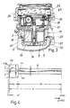
- a flow transducer 4a, 4b, 4c is formed in the inlet channels 2 in such a way that a deflection surface is produced on at least one of the two side walls 4.
- a first part 4a of the side wall 4 runs in a straight line up to a tear-off edge 4b, behind which a second part 4c of the side wall 4 begins, which is set back parallel to the first part 4a and is connected to it by a rounded transition.
- the flow transducers 31 are formed in each of the inlet ducts 2 in the side wall 4, on which the curve in front of the Tear edge 4b a deflection towards the axis of rotation is achieved.
- Fig. 1 it can be seen that the inlet channels 2 are halved by a partition 32, so that two sub-channels running parallel to each other are formed. This measure also changes the velocity profile of the inflowing liquid acting on the pallets of the impeller 16. It can be assumed that an even greater leveling of the speed profile can be achieved by an even more extensive subdivision, but this has been avoided for design reasons, in particular also because of the increasing reduction in the free cross section. However, tests have shown that the combination of a subdivision of the inlet channels 2 and the arrangement of flow transducers 31 in each of the sub-channels leads to a particularly favorable course of the error curve.
- FIG. 4 shows the course of such an error curve F2 in comparison to the usual error curve F1, which has a strong reduction in the usual excess in the lower measuring range MU, that is to say in the region of predominantly laminar flow.
- a course, as shown by the third error curve F3, can be achieved by arranging a flow transducer on a side wall, which is opposite the flow transducer 31 shown in the example. Such an arrangement of the flow transducer amplifies the torque in the lowest part of the measuring range M, so that the error curve F3 experiences a corresponding increase in this range. This ensures that water meters still register clearly even with very low water consumption. It can be assumed that by combining two themselves opposite flow transducers with a suitable design and arrangement, an error curve can be achieved, in which both the usual increase is reduced, and whose steep decline in the minus range begins relatively late.
Landscapes
- Physics & Mathematics (AREA)
- Fluid Mechanics (AREA)
- General Physics & Mathematics (AREA)
- Measuring Volume Flow (AREA)
- Details Of Flowmeters (AREA)
Applications Claiming Priority (2)
| Application Number | Priority Date | Filing Date | Title |
|---|---|---|---|
| DE3923142A DE3923142C2 (de) | 1989-07-13 | 1989-07-13 | Flügelradzähler zum Messen einer Flüssigkeitsmenge |
| DE3923142 | 1989-07-13 |
Publications (3)
| Publication Number | Publication Date |
|---|---|
| EP0407948A1 true EP0407948A1 (fr) | 1991-01-16 |
| EP0407948B1 EP0407948B1 (fr) | 1995-09-06 |
| EP0407948B2 EP0407948B2 (fr) | 2001-10-04 |
Family
ID=6384934
Family Applications (1)
| Application Number | Title | Priority Date | Filing Date |
|---|---|---|---|
| EP90113107A Expired - Lifetime EP0407948B2 (fr) | 1989-07-13 | 1990-07-09 | Compteur de liquide à turbine pour mesurer un débit |
Country Status (5)
| Country | Link |
|---|---|
| EP (1) | EP0407948B2 (fr) |
| DE (2) | DE3923142C2 (fr) |
| ES (1) | ES2079401T5 (fr) |
| FI (1) | FI97828C (fr) |
| ZA (1) | ZA905499B (fr) |
Cited By (5)
| Publication number | Priority date | Publication date | Assignee | Title |
|---|---|---|---|---|
| EP0713078A1 (fr) | 1994-11-15 | 1996-05-22 | E. Wehrle GmbH | Intercalation de mesure pour des compteurs de liquide |
| EP0718602A1 (fr) * | 1994-12-20 | 1996-06-26 | SCHLUMBERGER INDUSTRIES s.r.l. | Compteur de liquide à turbine du type à jet unique avec sensitivité améliorée et effet de régulation |
| FR2737563A1 (fr) * | 1995-08-04 | 1997-02-07 | Schlumberger Ind Sa | Compteur de liquide a jet unique a couple moteur ameliore |
| CH689953A5 (de) * | 1994-09-19 | 2000-02-15 | Gas & Wassermesserfab Ag | Flügelradzähler für Flüssigkeiten. |
| EP3730904A4 (fr) * | 2017-12-18 | 2021-08-25 | Joon Young Park | Dispositif et procédé de mesure de débit |
Families Citing this family (2)
| Publication number | Priority date | Publication date | Assignee | Title |
|---|---|---|---|---|
| DE10238417B4 (de) * | 2002-08-22 | 2004-09-02 | Invensys Metering Systems Gmbh Ludwigshafen | Mehrstrahlzähler |
| DE102005052953B4 (de) * | 2005-11-03 | 2010-06-17 | Axel Bohatsch | Vorrichtung zur Durchflussmessung von Flüssigkeiten an Einläufen in einem Abwasserschacht und Verfahren zur Bestimmung der Einlaufmengen in einem Abwasserkanalnetz |
Citations (6)
| Publication number | Priority date | Publication date | Assignee | Title |
|---|---|---|---|---|
| FR760336A (fr) * | 1932-07-09 | 1934-02-20 | Compteur de liquide à ailettes | |
| CH371269A (de) * | 1958-02-26 | 1963-08-15 | Presna Mechanika Narodny Podni | Mehrstrahl-Flügelrad-Wassermesser |
| DE1473148A1 (de) * | 1963-09-27 | 1970-01-02 | Pollux Gmbh | Messwerksbecher fuer Fluegelradzaehler |
| NL6913631A (fr) * | 1969-09-08 | 1971-03-10 | ||
| DE2647297B2 (de) * | 1976-10-20 | 1980-03-06 | Bopp & Reuther Gmbh, 6800 Mannheim | Flügelradzähler |
| EP0174552A1 (fr) * | 1984-09-07 | 1986-03-19 | Develconter R+D Ltd. | Compteur de fluide à rotor à jet unique |
Family Cites Families (7)
| Publication number | Priority date | Publication date | Assignee | Title |
|---|---|---|---|---|
| DE930351C (de) † | 1949-08-16 | 1955-07-14 | Hans Dipl-Ing Gehre | Drosselvorrichtung fuer Messradzaehler |
| US2636479A (en) * | 1950-05-29 | 1953-04-28 | Frederic C Ripley Sr | Flowmeter |
| DE1773498A1 (de) * | 1968-05-25 | 1971-10-14 | Neuhoff Paul & Co Gmbh | Mengenzaehler fuer stroemende Medien,insbesondere Wasserzaehler |
| FR2249315B1 (fr) * | 1973-10-29 | 1976-05-07 | Schlumberger Compteurs | |
| US3927568A (en) * | 1973-11-20 | 1975-12-23 | David E Hoppe | Means for improving linearity of bearingless flowmeter having ring-shaped rotor operating in combination with a vortex chamber by controlling turbulence produced by jet pathways |
| FR2581755B1 (fr) * | 1985-05-09 | 1987-06-12 | Sato Electronique Sa | Debitmetre a turbine pour fluides |
| DE8805780U1 (de) * | 1988-04-30 | 1988-06-09 | Bopp & Reuther Gmbh, 6800 Mannheim | Flügelradzähler |
-
1989
- 1989-07-13 DE DE3923142A patent/DE3923142C2/de not_active Revoked
-
1990
- 1990-07-09 EP EP90113107A patent/EP0407948B2/fr not_active Expired - Lifetime
- 1990-07-09 ES ES90113107T patent/ES2079401T5/es not_active Expired - Lifetime
- 1990-07-09 DE DE59009611T patent/DE59009611D1/de not_active Expired - Lifetime
- 1990-07-12 FI FI903530A patent/FI97828C/fi active IP Right Grant
- 1990-07-13 ZA ZA905499A patent/ZA905499B/xx unknown
Patent Citations (6)
| Publication number | Priority date | Publication date | Assignee | Title |
|---|---|---|---|---|
| FR760336A (fr) * | 1932-07-09 | 1934-02-20 | Compteur de liquide à ailettes | |
| CH371269A (de) * | 1958-02-26 | 1963-08-15 | Presna Mechanika Narodny Podni | Mehrstrahl-Flügelrad-Wassermesser |
| DE1473148A1 (de) * | 1963-09-27 | 1970-01-02 | Pollux Gmbh | Messwerksbecher fuer Fluegelradzaehler |
| NL6913631A (fr) * | 1969-09-08 | 1971-03-10 | ||
| DE2647297B2 (de) * | 1976-10-20 | 1980-03-06 | Bopp & Reuther Gmbh, 6800 Mannheim | Flügelradzähler |
| EP0174552A1 (fr) * | 1984-09-07 | 1986-03-19 | Develconter R+D Ltd. | Compteur de fluide à rotor à jet unique |
Non-Patent Citations (1)
| Title |
|---|
| PATENT ABSTRACTS OF JAPAN, vol. 7, no. 172 (P-213) (1317) 29 Juli 1983; & JP-A-58 077 619 (SANKOU K.K.) 11 Mai 1983 * |
Cited By (8)
| Publication number | Priority date | Publication date | Assignee | Title |
|---|---|---|---|---|
| CH689953A5 (de) * | 1994-09-19 | 2000-02-15 | Gas & Wassermesserfab Ag | Flügelradzähler für Flüssigkeiten. |
| EP0713078A1 (fr) | 1994-11-15 | 1996-05-22 | E. Wehrle GmbH | Intercalation de mesure pour des compteurs de liquide |
| DE4440683A1 (de) * | 1994-11-15 | 1996-05-23 | Wehrle E Gmbh | Meßeinsatz für Flüssigkeitszähler |
| EP0718602A1 (fr) * | 1994-12-20 | 1996-06-26 | SCHLUMBERGER INDUSTRIES s.r.l. | Compteur de liquide à turbine du type à jet unique avec sensitivité améliorée et effet de régulation |
| WO1996019714A1 (fr) * | 1994-12-20 | 1996-06-27 | Schlumberger Industries S.R.L. | Compteur a liquides, monojet, presentant une sensibilite et un effet de regulation ameliores |
| FR2737563A1 (fr) * | 1995-08-04 | 1997-02-07 | Schlumberger Ind Sa | Compteur de liquide a jet unique a couple moteur ameliore |
| WO1997006414A1 (fr) * | 1995-08-04 | 1997-02-20 | Schlumberger Industries S.A. | Compteur de liquide a jet unique a couple moteur ameliore |
| EP3730904A4 (fr) * | 2017-12-18 | 2021-08-25 | Joon Young Park | Dispositif et procédé de mesure de débit |
Also Published As
| Publication number | Publication date |
|---|---|
| FI97828B (fi) | 1996-11-15 |
| ZA905499B (en) | 1991-12-24 |
| FI97828C (fi) | 1997-02-25 |
| ES2079401T3 (es) | 1996-01-16 |
| EP0407948B1 (fr) | 1995-09-06 |
| ES2079401T5 (es) | 2002-03-16 |
| EP0407948B2 (fr) | 2001-10-04 |
| FI903530A0 (fi) | 1990-07-12 |
| DE3923142C2 (de) | 1999-11-04 |
| DE59009611D1 (de) | 1995-10-12 |
| DE3923142A1 (de) | 1991-01-24 |
Similar Documents
| Publication | Publication Date | Title |
|---|---|---|
| DE19927818C2 (de) | Vorrichtung zur Messung der Masse eines strömenden Mediums | |
| EP0198197B1 (fr) | Capteur de pression différentielle de débit | |
| DE2647297C3 (de) | Flügelradzahler | |
| EP1127249A1 (fr) | Dispositif de mesure d'au moins un parametre d'un agent s'ecoulant dans une conduite | |
| DE3873701T2 (de) | Ntroemungsrektifizierer fuer strudelstroemungsmesser. | |
| DE3032633A1 (de) | Flussmessgeraet | |
| DE10118415B4 (de) | Luftdurchsatzmessvorrichtung mit einem Turbulenzenreduzierungselement | |
| EP0407948B1 (fr) | Compteur de liquide à turbine pour mesurer un débit | |
| EP1127248A1 (fr) | Dispositif pour la mesure d'au moins un parametre d'un milieu en ecoulement dans une conduite | |
| EP0106010A1 (fr) | Tachymètre | |
| DE3002712C2 (fr) | ||
| EP0449861B1 (fr) | Rotor de pompe centrifuge a vitesse specifique reduite | |
| EP0713078A1 (fr) | Intercalation de mesure pour des compteurs de liquide | |
| DE1798360A1 (de) | Durchflussmeter | |
| DE69010338T2 (de) | Durchflussmengenmesser. | |
| DE68915278T2 (de) | Leitschaufel für axialgebläse. | |
| DE69120576T2 (de) | Thermischer Luftmengenmesser | |
| DE3940474C1 (fr) | ||
| EP0479879B1 (fr) | Compteur d'eau a volants a jet unique ou a jets multiples avec dispositif compensateur d'erreurs dues au vieillissement | |
| DE4403178C1 (de) | Volumendurchflußmesser | |
| DE19648591C1 (de) | Wirkdruckgeber eines Durchflußmessers | |
| DE3236154C2 (de) | Radialventilator | |
| DE4238149C2 (de) | Drucküberwachungseinrichtung für den Reinraum | |
| DE4207043A1 (de) | Messwertaufnehmer | |
| DE29719677U1 (de) | Durchflußmeßgerät |
Legal Events
| Date | Code | Title | Description |
|---|---|---|---|
| PUAI | Public reference made under article 153(3) epc to a published international application that has entered the european phase |
Free format text: ORIGINAL CODE: 0009012 |
|
| AK | Designated contracting states |
Kind code of ref document: A1 Designated state(s): DE ES IT NL SE |
|
| 17P | Request for examination filed |
Effective date: 19910705 |
|
| 17Q | First examination report despatched |
Effective date: 19930125 |
|
| GRAA | (expected) grant |
Free format text: ORIGINAL CODE: 0009210 |
|
| AK | Designated contracting states |
Kind code of ref document: B1 Designated state(s): DE ES IT NL SE |
|
| REF | Corresponds to: |
Ref document number: 59009611 Country of ref document: DE Date of ref document: 19951012 |
|
| ITF | It: translation for a ep patent filed | ||
| REG | Reference to a national code |
Ref country code: ES Ref legal event code: FG2A Ref document number: 2079401 Country of ref document: ES Kind code of ref document: T3 |
|
| PLBQ | Unpublished change to opponent data |
Free format text: ORIGINAL CODE: EPIDOS OPPO |
|
| PLBI | Opposition filed |
Free format text: ORIGINAL CODE: 0009260 |
|
| PLBF | Reply of patent proprietor to notice(s) of opposition |
Free format text: ORIGINAL CODE: EPIDOS OBSO |
|
| 26 | Opposition filed |
Opponent name: E. WEHRLE GMBH Effective date: 19960604 |
|
| NLR1 | Nl: opposition has been filed with the epo |
Opponent name: E. WEHRLE GMBH |
|
| PLBF | Reply of patent proprietor to notice(s) of opposition |
Free format text: ORIGINAL CODE: EPIDOS OBSO |
|
| PLAW | Interlocutory decision in opposition |
Free format text: ORIGINAL CODE: EPIDOS IDOP |
|
| PLAW | Interlocutory decision in opposition |
Free format text: ORIGINAL CODE: EPIDOS IDOP |
|
| PUAH | Patent maintained in amended form |
Free format text: ORIGINAL CODE: 0009272 |
|
| STAA | Information on the status of an ep patent application or granted ep patent |
Free format text: STATUS: PATENT MAINTAINED AS AMENDED |
|
| 27A | Patent maintained in amended form |
Effective date: 20011004 |
|
| AK | Designated contracting states |
Kind code of ref document: B2 Designated state(s): DE ES IT NL SE |
|
| NLR2 | Nl: decision of opposition | ||
| NLR3 | Nl: receipt of modified translations in the netherlands language after an opposition procedure | ||
| REG | Reference to a national code |
Ref country code: ES Ref legal event code: DC2A Kind code of ref document: T5 Effective date: 20020104 |
|
| EN | Fr: translation not filed | ||
| PGFP | Annual fee paid to national office [announced via postgrant information from national office to epo] |
Ref country code: ES Payment date: 20070727 Year of fee payment: 18 |
|
| PGFP | Annual fee paid to national office [announced via postgrant information from national office to epo] |
Ref country code: IT Payment date: 20070724 Year of fee payment: 18 |
|
| PGFP | Annual fee paid to national office [announced via postgrant information from national office to epo] |
Ref country code: NL Payment date: 20080716 Year of fee payment: 19 |
|
| PG25 | Lapsed in a contracting state [announced via postgrant information from national office to epo] |
Ref country code: IT Free format text: LAPSE BECAUSE OF NON-PAYMENT OF DUE FEES Effective date: 20080709 |
|
| REG | Reference to a national code |
Ref country code: ES Ref legal event code: FD2A Effective date: 20080710 |
|
| PG25 | Lapsed in a contracting state [announced via postgrant information from national office to epo] |
Ref country code: ES Free format text: LAPSE BECAUSE OF NON-PAYMENT OF DUE FEES Effective date: 20080710 |
|
| PGFP | Annual fee paid to national office [announced via postgrant information from national office to epo] |
Ref country code: DE Payment date: 20090722 Year of fee payment: 20 Ref country code: SE Payment date: 20090715 Year of fee payment: 20 |
|
| NLV4 | Nl: lapsed or anulled due to non-payment of the annual fee |
Effective date: 20100201 |
|
| EUG | Se: european patent has lapsed | ||
| PG25 | Lapsed in a contracting state [announced via postgrant information from national office to epo] |
Ref country code: NL Free format text: LAPSE BECAUSE OF NON-PAYMENT OF DUE FEES Effective date: 20100201 |
|
| PG25 | Lapsed in a contracting state [announced via postgrant information from national office to epo] |
Ref country code: DE Free format text: LAPSE BECAUSE OF EXPIRATION OF PROTECTION Effective date: 20100709 |