EP0407976A1 - Entladungsvorrichtung und Zündanordnung mit Serienfunkenstrecke unter Anwendung der Entladungsvorrichtung - Google Patents
Entladungsvorrichtung und Zündanordnung mit Serienfunkenstrecke unter Anwendung der Entladungsvorrichtung Download PDFInfo
- Publication number
- EP0407976A1 EP0407976A1 EP90113166A EP90113166A EP0407976A1 EP 0407976 A1 EP0407976 A1 EP 0407976A1 EP 90113166 A EP90113166 A EP 90113166A EP 90113166 A EP90113166 A EP 90113166A EP 0407976 A1 EP0407976 A1 EP 0407976A1
- Authority
- EP
- European Patent Office
- Prior art keywords
- discharge
- conductive member
- discharge device
- tube
- electrode
- Prior art date
- Legal status (The legal status is an assumption and is not a legal conclusion. Google has not performed a legal analysis and makes no representation as to the accuracy of the status listed.)
- Granted
Links
- 238000009826 distribution Methods 0.000 claims abstract description 12
- 230000005684 electric field Effects 0.000 description 31
- 238000009413 insulation Methods 0.000 description 28
- 239000002184 metal Substances 0.000 description 26
- 230000000694 effects Effects 0.000 description 25
- 239000007789 gas Substances 0.000 description 13
- 238000010304 firing Methods 0.000 description 12
- 230000002093 peripheral effect Effects 0.000 description 8
- 238000013459 approach Methods 0.000 description 7
- 238000005304 joining Methods 0.000 description 6
- 230000000087 stabilizing effect Effects 0.000 description 6
- 230000002265 prevention Effects 0.000 description 5
- 230000003247 decreasing effect Effects 0.000 description 4
- 238000004519 manufacturing process Methods 0.000 description 4
- 230000001965 increasing effect Effects 0.000 description 3
- 239000000463 material Substances 0.000 description 3
- 238000007789 sealing Methods 0.000 description 3
- 230000006641 stabilisation Effects 0.000 description 3
- 238000011105 stabilization Methods 0.000 description 3
- 238000012360 testing method Methods 0.000 description 3
- XKRFYHLGVUSROY-UHFFFAOYSA-N Argon Chemical compound [Ar] XKRFYHLGVUSROY-UHFFFAOYSA-N 0.000 description 2
- OKTJSMMVPCPJKN-UHFFFAOYSA-N Carbon Chemical compound [C] OKTJSMMVPCPJKN-UHFFFAOYSA-N 0.000 description 2
- 229910052799 carbon Inorganic materials 0.000 description 2
- 239000000919 ceramic Substances 0.000 description 2
- 230000007423 decrease Effects 0.000 description 2
- 230000002708 enhancing effect Effects 0.000 description 2
- 238000000034 method Methods 0.000 description 2
- 238000000465 moulding Methods 0.000 description 2
- 229910052786 argon Inorganic materials 0.000 description 1
- 238000005452 bending Methods 0.000 description 1
- 230000015572 biosynthetic process Effects 0.000 description 1
- 239000011248 coating agent Substances 0.000 description 1
- 238000000576 coating method Methods 0.000 description 1
- 238000010276 construction Methods 0.000 description 1
- 238000013461 design Methods 0.000 description 1
- 238000010586 diagram Methods 0.000 description 1
- 230000003467 diminishing effect Effects 0.000 description 1
- 239000012777 electrically insulating material Substances 0.000 description 1
- 230000008020 evaporation Effects 0.000 description 1
- 238000001704 evaporation Methods 0.000 description 1
- 239000011888 foil Substances 0.000 description 1
- 238000009434 installation Methods 0.000 description 1
- 239000011810 insulating material Substances 0.000 description 1
- 238000012986 modification Methods 0.000 description 1
- 230000004048 modification Effects 0.000 description 1
- 239000010705 motor oil Substances 0.000 description 1
- 239000003973 paint Substances 0.000 description 1
- 238000010422 painting Methods 0.000 description 1
- 239000004033 plastic Substances 0.000 description 1
- 229920003023 plastic Polymers 0.000 description 1
- 238000011160 research Methods 0.000 description 1
- 238000005476 soldering Methods 0.000 description 1
- 239000004071 soot Substances 0.000 description 1
- 238000004544 sputter deposition Methods 0.000 description 1
Images



Classifications
-
- H—ELECTRICITY
- H01—ELECTRIC ELEMENTS
- H01T—SPARK GAPS; OVERVOLTAGE ARRESTERS USING SPARK GAPS; SPARKING PLUGS; CORONA DEVICES; GENERATING IONS TO BE INTRODUCED INTO NON-ENCLOSED GASES
- H01T13/00—Sparking plugs
- H01T13/46—Sparking plugs having two or more spark gaps
- H01T13/462—Sparking plugs having two or more spark gaps in series connection
- H01T13/465—Sparking plugs having two or more spark gaps in series connection one spark gap being incorporated in the sparking plug
-
- H—ELECTRICITY
- H01—ELECTRIC ELEMENTS
- H01T—SPARK GAPS; OVERVOLTAGE ARRESTERS USING SPARK GAPS; SPARKING PLUGS; CORONA DEVICES; GENERATING IONS TO BE INTRODUCED INTO NON-ENCLOSED GASES
- H01T1/00—Details of spark gaps
- H01T1/20—Means for starting arc or facilitating ignition of spark gap
- H01T1/22—Means for starting arc or facilitating ignition of spark gap by the shape or the composition of the electrodes
-
- F—MECHANICAL ENGINEERING; LIGHTING; HEATING; WEAPONS; BLASTING
- F02—COMBUSTION ENGINES; HOT-GAS OR COMBUSTION-PRODUCT ENGINE PLANTS
- F02F—CYLINDERS, PISTONS OR CASINGS, FOR COMBUSTION ENGINES; ARRANGEMENTS OF SEALINGS IN COMBUSTION ENGINES
- F02F7/00—Casings, e.g. crankcases
- F02F7/006—Camshaft or pushrod housings
Definitions
- the present invention relates to a discharge device suitable for use in an ignition system with a series gap for automotive engines, and an ignition system with a series gap using the discharge device.
- Fig. 22 shows a discharge tube 1 used in for example an arrester for various kinds of electrical machinery and apparatus.
- this discharge tube 1 the open sections at both ends of an insulation tube 2 as a sealed tube formed of ceramics or other are closed with a pair of electrode plates 4, 4 having discharge electrode sections 3, 3 which are disposed opposingly.
- the insulation tube 2 is sealed a specific inactive gas.
- the discharge tube 1 Since the discharge tube 1 is placed and connected on a specific electric circuit of an arrester for example, there is arranged an electric element having a specific potential or a metal at a ground potential. If, in this manner, the discharge tube 1 is installed close to an electric element, an electric field formed around the electric element or other will affect the discharge tube 1, resulting in changed discharge voltage characteristics of the discharge tube 1.
- the ignition system C with series gap as shown in Fig. 24, has the spark-tension cable 6 connected to the high-voltage distribution side.
- a connection terminal 9 designed to fit on a terminal 8 of the spark plug 5 and a high-voltage distribution terminal 10 connected to the end of the high-tension cable 6.
- the discharge tube 1 having the discharge electrodes 3, 3 are mounted.
- the ignition system C of the above constitution is mounted in a recess section 12 formed in an engine cylinder head or a cylinder head cover 11, and attached on the spark plug 5 which is screwed into the cylinder head side.
- numeral 13 denotes a metal pipe which has the purpose of guiding the ignition system C and also protecting the ignition system C from fouling by engine oil.
- the metal pipe 13 which guides the ignition system C is located close thereto.
- the metal pipe 13 is at the same potential as the ground potential of the cylinder head or the cylinder head cover 11, the presence of the metal pipe 13 at this ground potential changes the field strength around the discharge tube 1, resulting in changed discharge voltage characteristics of the discharge tube 1.
- Such a change in the discharge voltage characteristics is likely to shift the whole ignition timing of the spark plug 5, and accordingly there is the problem that it is impossible to obtain specific automotive engine performance in which the accurate control of the spark plug ignition timing is required to obtain a high engine performance.
- the present invention has been accomplished in an attempt to resolve the problems mentioned above and has an object to provide a discharge device which can be protected from the effect of the electric field of surrounding electric elements or other and an ignition system with series gap capable of improving engine operation performance.
- the discharge device of the present invention which has a pair of electrodes opposing disposed in a sealed tube, is characterized by providing a conductive member enclosing one of the electrodes in the sealed tube.
- the ignition system with series gap of the present invention is an ignition system having a built-in discharge device provided with a series gap, with one end connected to the center electrode side of the spark plug and with the other end connected to the high-tension cable side extending from the high-voltage distribution side.
- a discharge device having a conductive member which encloses one of the electrodes of the sealed tube, and one of the electrodes enclosed with the conductive member of this discharge device works as a cathode.
- the ignition system with series gap which includes a discharge tube provided with the series gap with one end connected to the center electrode side of the spark plug and the other end connected to the high-tension cable side extending from the high-voltage distribution side, there is provided a conductive member enclosing the cathode side of the discharge device to be installed in the casing in which the discharge device is to be installed.
- a conductive member enclosing one of electrodes in the sealed tube and, therefore, when a minus voltage is applied to the electrode around which the conductive member is installed, to discharge electrons from this electrode (cathode), the conductive member works to prevent the effect of the surrounding electric field for the purpose of stabilizing the electric field in the vicinity of the cathode side in the discharge device, thereby enabling stabilizing the discharge voltage characteristics of the discharge device.
- a discharge device provided with a conductive member which encloses one of the electrodes of the sealed tube is used as the discharge device installed as the series gap, and one of the electrodes enclosed with the conductive member of the discharge device operates as the cathode. Therefore, when the minus voltage is applied to the discharge member from the high-tension cable, the conductive member can prevent the effect of the surrounding electric field, thereby stabilizing the electric field around the cathode side in the discharge device and getting rid of a change in the discharge voltage characteristics of the discharge device for the purpose of preventing the overall shift of the ignition timing and enhancing engine performance.
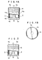
- Figs. 1A and 1B show a first embodiment of a discharge tube 1 used as a discharge device according to the present invention.
- the hollow cylindrical insulation tube 2 as a sealed tube produced of ceramics is sealed at open sections at both ends with a pair of metal electrode plates 4a and 4b having the opposing discharge electrodes 3a and 3b, and in the insulation tube 2 is filled a specific inactive gas, such as argon gas, through a sealing pipe not illustrated.
- a specific inactive gas such as argon gas
- a nearly cap-like conductive member 14 used as a back electrode is mounted on the outer periphery of the discharge tube 1 as if to surround the electrode plate 4a and a discharge electrode section 3a thereof.
- This conductive member 14 is designed to be electrically connected to the electrode plate 4a by a specific means which is not illustrated.
- the conductive member 14 is produced of for example a metal sheet, and the inner surface of the condutive member 14 and the outer surface of the discharge tube 1 may be either in close contact with or apart from each other with a specific amount of spacing formed therebetween.
- the discharge tube 1 is used so that the high minus voltage is applied to one electrode plate 4a side enclosed by the conductive member 14, and that the other electrode plate 4b side will be the ground side. Therefore, under the using conditions of the discharge device, the electrode plate 4a side operates as a cathode at which electrons are emitted by a discharge phenomenon, while the other electrode plate 4b side functions as an anode.
- the conductive member 14 used around the discharge tube 1 to surround the electrode plate 4a on the cathode side and the discharge electrode section 3a, and the conductive member 14 and the electrode plate 4a are electrically connected; therefore, if the discharge electrode section 3a and the conductive member 14 are of the same potential and there is provided an electric element (not illustrated) having a specific potential in the vicinity of the discharge tube 1, forming a specific electric field around the electric element and other, a stabilized electric field can be formed between the discharge electrode section 3a and the discharge electrode 3b on the opposite side without disturbing the electric field around the cathode side in the discharge tube 1, thereby providing a stabilized discharge phenomenon and also stabilized discharge voltage characteristics between these discharge electrode sections 3a and 3b.
- Table 1 This is clear also from experimental data shown in Table 1.
- the firing potential of 16.5 - 17.5 kV drops to 14 - 15 kV when the electric element or other for example at the ground potential approaches, a voltage fluctuation reaching as great as 2 kV.
- the firing potential of 10 - 20 kV varies only to 19.5 - 20.5 kV when the ground body approaches, the range of this fluctuation therefore being merely 0.5 kV.
- the conductive member 14 which is at the same potential as the discharge electrode section 3a and protects the vicinity of the cathode side in the discharge tube 1 from the effect of the ambient electric field.
- the fluctuation of the firing potential becomes extremely little, thereby enabling the stabilization of the discharge voltage characteristics.
- the voltage fluctuation can be improved by the ground body within the range that, as shown by an alternate long and two short dashes line in Fig. 1A, the lower end 14a of the conductive member 14 installed over the electrode plate 4a on the cathode side fully reaches the vicinity of the upper end of the discharge electrode section 3a on the cathode side.
- Fig. 2 shows a second embodiment of the discharge tube 1 according to the present invention, wherein a metallized band 15 of specific width is formed on the outer peripheral surface of one open end of the insulation tube 2 at the time of metallizing the open end of the insulation tube 2.
- a metallized band 15 of specific width is formed on the outer peripheral surface of one open end of the insulation tube 2 at the time of metallizing the open end of the insulation tube 2.
- this embodiment also, it is possible to prevent the effect of a surrounding electric field and to form the conductive member simultaneously with metallizing, thereby reducing the number of processes and a manufacturing cost.
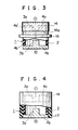
- the insulation distance from the lower end 14a of the conductive member to the end face 4b' of the electrode plate 4b on the anode side to be joined to the insulated tube 2 decreases as shown in Fig. 3, and accordingly it is likely that there occurs a so-called surface discharge along the outside wall surface of the insulation tube 2 across this insulation distance.
- Forming the collar section 16 as described above makes substantially longer the tube (insulation distance) along the outer surface of the insulation tube 2 from the joining end face 4a′ joining the cathode-side electrode plate 4a to the insulation tube 2 to the joining end face 4b′ of the anode-side electrode plate, making it difficult to produce the surface discharge. Also, moulding the electrically insulating material 17 dispenses with a part, such as an air stratum on the outside surface of the insulation tube 2, which induces the surface discharge, thus enabling the prevention of the surface discharge.
- the discharge electrode 3a on the cathode side is formed extremely short and at the same time the discharge electrode section 3b on the anode side is increased in length by an amount equal to the decreased amount of the discharge electrode 3a. Also, there is formed for example a metallized band 15 extremely short but wide just enough to surround the short discharge electrode section 3a, in order that the metallized band 15 and the electrode plate 4a having the discharge electrode section 3a thus formed are electrically connected.
- the inactive gas is filled and a gas filling pipe is attached to one of the electrode plates 4 for sealing the open end sections of the insulation tube 2 comprising the discharge tube 1.
- This gas filling pipe is coaxially extending into the discharge electrode section 3 of the electrode plate 4 on which the gas filling pipe is attached, with a pipe end being open into the insulation tube 2.
- the discharge electrode section 3b is formed extremely long on the anode side, the provision of the gas filling pipe 18 on the discharge electrode section 3b side can open a pipe end 18a, which is formed by bending the forward end portion of the gas filling pipe, to the peripheral surface of the discharge electrode section 3b.
- the gas filling pipe 18 does not pass through to the discharge face 3b ⁇ at the top end of the discharge electrode 3b, and therefore the discharge face 3b′ at the top end of the discharge electrode 3b can be increased in surface area, thereby diminishing the influence of electrode consumption for the purpose of prolonging the life of the discharge tube 1.
- a sixth embodiment shown in Fig. 6 sets forth the cathode-side discharge electrode 3a of the fifth embodiment which is further decreased in length, so that the discharge electrode 3a does almost or completely not project out of the cathode-side electrode plate 4a.
- the electrode plate 4a works as a conductive member which functions as a back electrode described above, displaying an effect approximately similar to that of the back electrode particularly even when no back electrode is provided. As no back electrode is in use, it is possible to lower the cost of the whole body of the discharge tube 1 and also to prevent the surface discharge described above.
- the cathode side electrode plate 4a which acts as the above-mentioned back electrode may be made substantially in the form of a cap having a slight protuberance formed in its inner surface thereof to act as discharge electrode section 3a.
- the eighth embodiment shown in Fig. 8 the discharge electrode is not in the protruding form, even in which case an approximately similar result to the back electrode is obtained and the surface discharge is prevented from being generated.
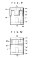
- Fig. 9 shows a ninth embodiment of the discharge tube 1 according to the present invention, wherein the conductive member 14 used as the back electrode is provided with a plurality of cutouts 19 within the range that the lower end section 3a′ of the discharge electrode 3a on the cathode side will never be affected by an ambient electric field.
- the present invention it is possible to stabilize the discharge voltage characteristics between the discharge electrode sections 3a and 3b without disturbing the vicinity of the cathode side in the discharge tube 1 by the ambient electric field. Furthermore, as it is unnecessary to use the conductive member in the area the cutout section 19 is formed, it is possible to decrease materials and accordingly to reduce the manufacturing cost.
- Fig. 10 shows a tenth embodiment of the discharge tube 1 according to the present invention, wherein continuous one turn of a metal wire 20 is electrically connected to the electrode plate 4a through a lead section 20a on the outer peripheral surface of the insulation tube 2 in a position slightly closer to the electrode plate 4a from the lower end 3a ⁇ of the cathode-side discharge electrode section 3a.
- the metal wire 20 functions as the conductive member used as what is called the back electrode, thus preventing the effect of the ambient electric field. Even when the ground boy is located nearly the firing potential of 20 - 20.5 kV varies only to 19 - 19.5 kV as shown in Table 1 given later on, its discharge voltage characteristics remaining stabilized. As the back electrode is composed merely of the metal wire 20, the discharge device can be produced at an extremely low cost.
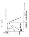
- This metal wire 20 should be installed slightly closer to the electrode plate 4a side than to the lower end 3a ⁇ of the cathode-side discharge electrode section 3a. In this position the highest firing potential and the maximum effect thereof are obtainable as is clear from the relationship between the firing potential and the location of the metal wire shown in Fig. 11.
- the metal wire 20 may be a discontinued one turn of metal wire having a plurality of discontinuities within the range that the lower end section 3a′ of the cathode-side discharge electrode 3a will not be affected by the ambient electric field, or may have a plurality of turns of metal wire.
- a metal wire 21 whose one end is connected to the cathode-side electrode plate 4a may be wound into a form of coil spring on the outer peripheral surface of the insulation tube 2.
- Fig. 13 shows a twelfth embodiment of the discharge tube 1 according to the present invention.
- a band-like conductive member 22 which surround the discharge electrode section 3a, extending from a position 1 to 2 mm apart from the joining end 4a′ of the cathode-side electrode plate 4a which is joined to the insulation tube 2, to the lower end 3a ⁇ of the discharge electrode section.
- the conductive member 22 functions as the so-called back electrode to shut off the effect of the ambient electric field, fully displaying its effect particularly when the high minus voltage is applied to the cathode side of the discharge tube 1 (when the spacing is several millimeters or larger, the conductive member 22 can still show an effect as the back electrode though not fully).
- the conductive member 22 there occurs, therefore, no disturbance by the conductive member 22 in the vicinity of the cathode side in the discharge tube 1, thereby enabling the stabilization of the discharge voltage characteristics between the discharge electrode sections 3a and 3b.
- the manufacturing cost can be lowered further.
- the conductive member described above may be either a conductive member 23 which is not continuous with a plurality of discontinuities as set forth in a thirteenth embodiment shown in Fig. 14 or a mesh-like conductive member 24 described in a fourteenth embodiment shown in Fig. 15. Furthermore, it is possible to provide a set of metal rings 25 put in a plurality of layers or a metal wire 26 in a form of coil spring, as described in fifteenth and sixteenth embodiments shown in Figs. 16 and 17 respectively.
- Each of the conductive members described above in the first to sixteenth embodiments can be formed by varied processes, besides the above-mentioned, such as metal foiling, metallizing, conductive painting, evaporation coating, sputtering, etc.
- the location of the conductive member is not limited to the outer peripheral section of the discharge tube 1, but may be the inner peripheral section of the discharge tube 1.
- the installation of the conductive member on the inner periphery of the discharge tube 1 is likely to cause the surface discharge to occur inside of the discharge tube; it is, therefore, necessary to adopt some effective means for prevention of the surface discharge.
- the conductive member may be embedded in a specific location in the wall of the insulation tube 2 at the stage of manufacture, not installed on the outer or inner periphery of the discharge tube 1.
- the discharge tube 1 is given as one example of the discharge device with a pair of electrodes disposed opposingly with a specific discharge gap provided therebetween and sealed in a sealed tube, and with an inactive gas filled in this sealed tube, and that the discharge device of the present invention is not limited only to the discharge tube 1.
- Table 1 shows, as a test data which shows the effect of the aforementioned conductive member, the values of firing potential of the discharge tube body of each of the embodiments, and the values of firing potential obtained when the ground body approaches, in comparison with conventional examples shown in Fig. 22.
- Table 1 (Unit: kV) Discharge tube body alone When ground body approaches Conventional example 16.5 to 17.5 14 to 15 Fig. 1 19 to 20 19.5 to 20.5 Fig. 5 16.5 to 17.5 16.5 to 17.5 Fig. 10 20 to 20.5 19 to 19.5 Fig. 13 19.5 to 20.5 19 to 20 Fig. 14 19 to 20 19 to 20 Fig. 15 18.5 to 20 20 to 20.5
- Fig. 18 shows a first embodiment of the ignition system C with series gap which uses the discharge device 1 according to the present invention, wherein, in the plug cap 7 embedded in the metal pipe connected to the cylinder head or the cylinder head cover 11, there is installed the discharge tube 1 having the cap-shaped conductive member 14 as a back electrode which covers one electrode side 4a, 3a shown in Fig. 1A.
- this discharge tube 1 is installed in such a manner that its one end provided with the conductive member 14 is connected to the high-tension cable side extending from the high-tension coil which produces the minus voltage, while the other end having no conductive member 14 is connected to the center electrode side of the spark plug.
- the discharge device is adapted to be used such that one electrode side 4a, 3a of the discharge tube 1 will work as a cathode from which the electrons are emitted in the discharge phenomenon and the other electrode side 4b, 3b will work as the anode.
- the discharge tube 1 functions as the series gap S provided in series with the spark plug, and the discharge voltage present across this series gap is maintained at a high value to a certain degree.
- the voltage present in this series gap after discharge is applied to the spark plug all at once, thereby obtaining an ignition voltage necessary for the spark plug without being affected by a short circuit caused by carbon deposits on the spark plug.
- the discharge tube 1 is used so that the cathode side 4a, 3a which emits the electrons in the discharge phenomenon may be covered with the conductive member 14, the discharge tube 1 will become free from a change in the electric field strength caused by the metal pipe 13 which is at ground potential, thereby enabling discharge stabilization.
- the discharge tube 1 will become free from a change in the electric field strength caused by the metal pipe 13 which is at ground potential, thereby enabling discharge stabilization.
- Fig. 19 shows a second embodiment of the ignition system C with a series gap according to the present invention.
- the discharge tube 1 having the conductive member is not used, but the conductive member as the back electrode is mounted on the plug cap 7 side and the discharge tube 1 of prior art shown in Fig. 22 is employed.
- This conductive member 27 is connected by a wire to the high-voltage distribution terminal 10 in order to maintain the same potential as the high-voltage distribution terminal 10 side.
- high-voltage terminal 10 side to which the minus voltage is applied is the cathode
- the connection terminal 9 connected to the center electrode of the spark plug is the anode.
- the discharge tube 1 is not affected by any change in the electric field strength caused by the metal pipe 13 at the ground potential which guides and protects the plug cap 7, and it is possible to prevent the overall shift of the ignition timing by stabilizing the discharge voltage characteristics, thereby improving the engine operation performance.
- numeral 28 denotes an electrical insulating moulded material of plastics or other for holding and fixing the discharge tube 1 within the plug cap 7.
- the conductive member 27, as described above, must not be serial one but may have a plurality of discontinuities. Also, as stated in the third embodiment shown in Fig. 20, the coil spring-shaped metal wire 29 may be used. Furthermore, the effect of an ambient electric field can be fully prevented if the conductive member 27 is not electrically connected with the high-voltage terminal 10, and the conductive member 27 may be formed of various kinds of materials such as metal foil, metal mesh, conductive paint, etc.
- the discharge device functioning as the series gap has been explained separately from the spark plug.
- the present invention should not be limited to the aforementioned embodiments; the discharge device used as the series gap may be such a device formed integral with the plug built in the spark plug.
- Table 2 gives a test data showing the effect of the ignition system C with a series gap having the conductive member, comparing a conventional example shown in Fig. 24 with the values of the firing potential of the assembly body with the discharge member 27 of the second embodiment both electrically connected and not electrically connected to the cathode side of the discharge tube 1, and the values of the firing potential with the ground body having approached them.
- Table 2 (Unit: kV) Assembly body alone Ground body approaches Conventional example 16.5 to 17.5 14.5 to 15.5 Conductive member is connected to discharge tube 18.6 to 19.5 18.5 to 19.5 Conductive member is not connected to discharge tube 18 to 19 18 to 19
- the conductive member since the conductive member is provided to substantially surround one of the electrodes of the sealed tube, the conductive member shuts off the effect of the ambient electric field to stabilize the electric field in the discharge device when the electrons are emitted from the cathode provided with the conductive member applied with the minus voltage, thus stabilizing the discharge voltage characteristics of the discharge device.
- the ignition system with a series gap uses a discharge device having the conductive member which substantially surround one of the electrodes of the sealed tube, for a discharge device installed as a series gap in the engine cylinder, such that one of the electrons enclosed by conductive member will be a cathode.
- the conductive member prevents the effect of the surrounding electric field in order to stabilize the electric field around the cathode side in the discharge device without a change in the discharge voltage characteristics of the discharge device, thereby preventing the overall shift of the ignition timing and accordingly further enhancing the engine performance.
- the conductive member substantially surround the cathode section of the discharge device is installed in the casing in which the discharge device is to be installed as a series gap, the conductive member prevents the effect of the surrounding electric field and stabilize the electric field in the vicinity of the cathode side in the discharge device without affecting the discharge voltage characteristics of the discharge device, thereby preventing the overall shift of the ignition timing and further improving the engine performance.
Landscapes
- Ignition Installations For Internal Combustion Engines (AREA)
- Spark Plugs (AREA)
Priority Applications (1)
| Application Number | Priority Date | Filing Date | Title |
|---|---|---|---|
| EP94117046A EP0635918A3 (de) | 1989-07-12 | 1990-07-10 | Entladungsvorrichtung und Zündanordnung mit Seriespalt mit Entladungsvorrichtung. |
Applications Claiming Priority (6)
| Application Number | Priority Date | Filing Date | Title |
|---|---|---|---|
| JP17807489 | 1989-07-12 | ||
| JP178074/89 | 1989-07-12 | ||
| JP17807489 | 1989-07-12 | ||
| JP26805489A JPH0697628B2 (ja) | 1989-07-12 | 1989-10-17 | シリーズギャップ付点火装置 |
| JP268054/89 | 1989-10-17 | ||
| JP26805489 | 1989-10-17 |
Related Child Applications (2)
| Application Number | Title | Priority Date | Filing Date |
|---|---|---|---|
| EP94117046A Division EP0635918A3 (de) | 1989-07-12 | 1990-07-10 | Entladungsvorrichtung und Zündanordnung mit Seriespalt mit Entladungsvorrichtung. |
| EP94117046.6 Division-Into | 1990-07-10 |
Publications (2)
| Publication Number | Publication Date |
|---|---|
| EP0407976A1 true EP0407976A1 (de) | 1991-01-16 |
| EP0407976B1 EP0407976B1 (de) | 1999-12-01 |
Family
ID=26498377
Family Applications (1)
| Application Number | Title | Priority Date | Filing Date |
|---|---|---|---|
| EP90113166A Expired - Lifetime EP0407976B1 (de) | 1989-07-12 | 1990-07-10 | Entladungsvorrichtung und Zündanordnung mit Serienfunkenstrecke unter Anwendung der Entladungsvorrichtung |
Country Status (4)
| Country | Link |
|---|---|
| US (1) | US5080083A (de) |
| EP (1) | EP0407976B1 (de) |
| CA (1) | CA2020586C (de) |
| DE (1) | DE69033373T2 (de) |
Cited By (4)
| Publication number | Priority date | Publication date | Assignee | Title |
|---|---|---|---|---|
| US5642721A (en) * | 1992-01-06 | 1997-07-01 | Ikeya; Kaname | Double ignition system for internal combustion engines, ignition plug for double ignition systems, and electric spark generator |
| US9221209B2 (en) | 2011-01-14 | 2015-12-29 | The Procter & Gamble Company | Process for the manufacture of a container |
| US9346200B2 (en) | 2011-01-14 | 2016-05-24 | The Procter & Gamble Company | Closure for a container |
| US9994368B2 (en) | 2012-10-30 | 2018-06-12 | The Procter & Gamble Company | Closure for a container |
Families Citing this family (7)
| Publication number | Priority date | Publication date | Assignee | Title |
|---|---|---|---|---|
| JPH04203269A (ja) * | 1990-11-29 | 1992-07-23 | Yazaki Corp | 高圧ケーブル装置 |
| JPH04349386A (ja) * | 1991-05-27 | 1992-12-03 | West Electric Co Ltd | 内燃機関点火装置用の定電圧放電管 |
| JPH0785840A (ja) * | 1993-09-20 | 1995-03-31 | Yazaki Corp | ガス入り放電管 |
| JPH07192841A (ja) * | 1993-12-27 | 1995-07-28 | Yazaki Corp | 放電管 |
| JP3092783B2 (ja) * | 1995-05-12 | 2000-09-25 | 矢崎総業株式会社 | 点火プラグキャップ |
| CN102720621A (zh) * | 2012-07-10 | 2012-10-10 | 孙洪宽 | 一种连接汽车高压点火线圈的节油、节气减排装置 |
| US10543145B1 (en) | 2014-04-30 | 2020-01-28 | Daniel J. McGuire | Adjustable slip resistant walking surface for use with a mobility aid |
Citations (6)
| Publication number | Priority date | Publication date | Assignee | Title |
|---|---|---|---|---|
| DE744101C (de) * | 1939-10-14 | 1944-01-18 | Siemens Ag | Anordnung zur Herabsetzung der Temperaturabhaengigkeit der Ansprechspannung von Funkenstrecken |
| DE6607772U (de) * | 1968-01-24 | 1971-04-15 | Siemens Ag | Ueberspannungsableiter |
| FR2475797A3 (fr) * | 1980-02-11 | 1981-08-14 | Cerberus Ag | Limiteur de tension et son procede de fabrication |
| GB2124426A (en) * | 1982-07-28 | 1984-02-15 | Esref Halilovic | Internal combustion engine spark ignition system components |
| US4475055A (en) * | 1982-01-28 | 1984-10-02 | The United States Of America As Represented By The United States Department Of Energy | Spark gap device for precise switching |
| EP0378963A1 (de) * | 1989-01-18 | 1990-07-25 | Siemens Aktiengesellschaft | Funkenstreckenbauelement für geschirmte Anordnung |
Family Cites Families (17)
| Publication number | Priority date | Publication date | Assignee | Title |
|---|---|---|---|---|
| US1554252A (en) * | 1925-09-22 | Poration | ||
| US1316560A (en) * | 1919-09-23 | conrad | ||
| US1169744A (en) * | 1914-12-17 | 1916-01-25 | Jubilee Mfg Company | Spark-intensifier for spark-plugs. |
| US1442947A (en) * | 1919-12-22 | 1923-01-23 | Basil M Allen | Spark-plug intensifier |
| US1406858A (en) * | 1920-05-28 | 1922-02-14 | George F Kreitlein | Vacuum spark amplifier |
| US1441212A (en) * | 1921-11-10 | 1923-01-09 | Cardwell Ernest Henry | Spark intensifier for ignition circuits |
| US1623982A (en) * | 1924-10-06 | 1927-04-12 | George M Smith | Spark intensifier for electric currents |
| US1909255A (en) * | 1931-05-12 | 1933-05-16 | Herbert Redman | Spark intensifier |
| US2208030A (en) * | 1939-11-06 | 1940-07-16 | Holmes Induction Deviees Inc | Spark plug |
| FR1136437A (fr) * | 1955-09-28 | 1957-05-14 | Perfectionnements aux dispositifs d'allumage pour moteurs à explosion | |
| US3613653A (en) * | 1970-03-23 | 1971-10-19 | Eugene Irvin Jr | Ignition device for internal combustion engine |
| GB1400446A (en) * | 1971-07-17 | 1975-07-16 | Lucas Industries Ltd | Spark ignition circuits |
| DE2418261B2 (de) * | 1974-04-16 | 1976-05-13 | Siemens AG, 1000 Berlin und 8000 München | Funkenstreckenbauelement fuer zuendanlagen von brennkaftmaschinen |
| JPS5132180A (ja) * | 1974-09-12 | 1976-03-18 | Mitsubishi Electric Corp | Handotaisochisetsuzokusochi |
| YU286278A (en) * | 1978-12-07 | 1983-12-31 | Esref Halilovic | Photoactive ionizing high-voltage pulsator of a system for starting engines having carburetors |
| JPS63313487A (ja) * | 1987-06-13 | 1988-12-21 | Horiba Ltd | ギヤツプスイツチ |
| US5014656A (en) * | 1990-04-25 | 1991-05-14 | General Motors Corporation | Internal combustion engine having a permanent ground electrode and replaceable center electrode element |
-
1990
- 1990-07-05 US US07/548,533 patent/US5080083A/en not_active Expired - Lifetime
- 1990-07-06 CA CA002020586A patent/CA2020586C/en not_active Expired - Fee Related
- 1990-07-10 EP EP90113166A patent/EP0407976B1/de not_active Expired - Lifetime
- 1990-07-10 DE DE69033373T patent/DE69033373T2/de not_active Expired - Fee Related
Patent Citations (6)
| Publication number | Priority date | Publication date | Assignee | Title |
|---|---|---|---|---|
| DE744101C (de) * | 1939-10-14 | 1944-01-18 | Siemens Ag | Anordnung zur Herabsetzung der Temperaturabhaengigkeit der Ansprechspannung von Funkenstrecken |
| DE6607772U (de) * | 1968-01-24 | 1971-04-15 | Siemens Ag | Ueberspannungsableiter |
| FR2475797A3 (fr) * | 1980-02-11 | 1981-08-14 | Cerberus Ag | Limiteur de tension et son procede de fabrication |
| US4475055A (en) * | 1982-01-28 | 1984-10-02 | The United States Of America As Represented By The United States Department Of Energy | Spark gap device for precise switching |
| GB2124426A (en) * | 1982-07-28 | 1984-02-15 | Esref Halilovic | Internal combustion engine spark ignition system components |
| EP0378963A1 (de) * | 1989-01-18 | 1990-07-25 | Siemens Aktiengesellschaft | Funkenstreckenbauelement für geschirmte Anordnung |
Cited By (4)
| Publication number | Priority date | Publication date | Assignee | Title |
|---|---|---|---|---|
| US5642721A (en) * | 1992-01-06 | 1997-07-01 | Ikeya; Kaname | Double ignition system for internal combustion engines, ignition plug for double ignition systems, and electric spark generator |
| US9221209B2 (en) | 2011-01-14 | 2015-12-29 | The Procter & Gamble Company | Process for the manufacture of a container |
| US9346200B2 (en) | 2011-01-14 | 2016-05-24 | The Procter & Gamble Company | Closure for a container |
| US9994368B2 (en) | 2012-10-30 | 2018-06-12 | The Procter & Gamble Company | Closure for a container |
Also Published As
| Publication number | Publication date |
|---|---|
| DE69033373D1 (de) | 2000-01-05 |
| CA2020586A1 (en) | 1991-01-13 |
| CA2020586C (en) | 1993-07-20 |
| EP0407976B1 (de) | 1999-12-01 |
| DE69033373T2 (de) | 2000-08-24 |
| US5080083A (en) | 1992-01-14 |
Similar Documents
| Publication | Publication Date | Title |
|---|---|---|
| US4914344A (en) | Spark plug for internal combustion engines | |
| US4439707A (en) | Spark plug with a wide discharge gap | |
| EP0951027B1 (de) | Zündspulenvorrichtung für Verbrennungsmotor | |
| US4327702A (en) | Plasma jet ignition system with noise suppressing arrangement | |
| EP0407976B1 (de) | Entladungsvorrichtung und Zündanordnung mit Serienfunkenstrecke unter Anwendung der Entladungsvorrichtung | |
| US6329743B1 (en) | Current peaking sparkplug | |
| US4476412A (en) | Spark plug | |
| TW201742343A (zh) | 用於高頻點火系統的火星塞 | |
| US20040079139A1 (en) | Ignition apparatus for internal combustion engine | |
| US4658774A (en) | Ignition apparatus for internal combustion engines | |
| EP0635918A2 (de) | Entladungsvorrichtung und Zündanordnung mit Seriespalt mit Entladungsvorrichtung | |
| EP1990536B1 (de) | Doppelzündspule mit Möglichkeiten zum Ausgleich der elektrischen Kapazität | |
| US5142194A (en) | Spark gap component of particular spacing mounted within a shield | |
| US5438970A (en) | High tension cord connector with misfire detecting capacitor for internal combustion engine | |
| JP2569743B2 (ja) | 点火コイルのプラグキャップ | |
| EP0407975B1 (de) | Hochspannungskabel | |
| EP0433870A1 (de) | Einrichtung für Hochspannungskabel | |
| JPH03163778A (ja) | 放電管及びその放電管を使用したシリーズギャップ付点火装置 | |
| EP0619631A1 (de) | Zündkerzenvorrichtung | |
| EP0056957A1 (de) | Zündverteiler für Brennkraftmaschinen mit innerer Verbrennung | |
| JP2725763B2 (ja) | 放電管及びシリーズギャップ付点火装置 | |
| KR0137338Y1 (ko) | 나사형 간극조절식 점화플러그 | |
| KR0137694Y1 (ko) | 간극조절식 점화플러그 | |
| JPH04349386A (ja) | 内燃機関点火装置用の定電圧放電管 | |
| JPH01294968A (ja) | 内燃機関用配電器キヤツプ |
Legal Events
| Date | Code | Title | Description |
|---|---|---|---|
| PUAI | Public reference made under article 153(3) epc to a published international application that has entered the european phase |
Free format text: ORIGINAL CODE: 0009012 |
|
| AK | Designated contracting states |
Kind code of ref document: A1 Designated state(s): DE GB |
|
| 17P | Request for examination filed |
Effective date: 19910307 |
|
| 17Q | First examination report despatched |
Effective date: 19930517 |
|
| GRAG | Despatch of communication of intention to grant |
Free format text: ORIGINAL CODE: EPIDOS AGRA |
|
| GRAG | Despatch of communication of intention to grant |
Free format text: ORIGINAL CODE: EPIDOS AGRA |
|
| GRAH | Despatch of communication of intention to grant a patent |
Free format text: ORIGINAL CODE: EPIDOS IGRA |
|
| GRAH | Despatch of communication of intention to grant a patent |
Free format text: ORIGINAL CODE: EPIDOS IGRA |
|
| GRAA | (expected) grant |
Free format text: ORIGINAL CODE: 0009210 |
|
| AK | Designated contracting states |
Kind code of ref document: B1 Designated state(s): DE GB |
|
| XX | Miscellaneous (additional remarks) |
Free format text: TEILANMELDUNG 94117046.6 EINGEREICHT AM 10/07/90. |
|
| REF | Corresponds to: |
Ref document number: 69033373 Country of ref document: DE Date of ref document: 20000105 |
|
| PLBE | No opposition filed within time limit |
Free format text: ORIGINAL CODE: 0009261 |
|
| STAA | Information on the status of an ep patent application or granted ep patent |
Free format text: STATUS: NO OPPOSITION FILED WITHIN TIME LIMIT |
|
| 26N | No opposition filed | ||
| REG | Reference to a national code |
Ref country code: GB Ref legal event code: IF02 |
|
| PGFP | Annual fee paid to national office [announced via postgrant information from national office to epo] |
Ref country code: GB Payment date: 20050706 Year of fee payment: 16 |
|
| PGFP | Annual fee paid to national office [announced via postgrant information from national office to epo] |
Ref country code: DE Payment date: 20050707 Year of fee payment: 16 |
|
| PG25 | Lapsed in a contracting state [announced via postgrant information from national office to epo] |
Ref country code: GB Free format text: LAPSE BECAUSE OF NON-PAYMENT OF DUE FEES Effective date: 20060710 |
|
| PG25 | Lapsed in a contracting state [announced via postgrant information from national office to epo] |
Ref country code: DE Free format text: LAPSE BECAUSE OF NON-PAYMENT OF DUE FEES Effective date: 20070201 |
|
| GBPC | Gb: european patent ceased through non-payment of renewal fee |
Effective date: 20060710 |