EP0408021A1 - Dispositif pour transporter et positioner des pièces à usiner en forme de disque, notamment des disques semi-conducteurs et procédé pour le traitement chimique en surface, par voie humide de celles-ci - Google Patents
Dispositif pour transporter et positioner des pièces à usiner en forme de disque, notamment des disques semi-conducteurs et procédé pour le traitement chimique en surface, par voie humide de celles-ci Download PDFInfo
- Publication number
- EP0408021A1 EP0408021A1 EP90113307A EP90113307A EP0408021A1 EP 0408021 A1 EP0408021 A1 EP 0408021A1 EP 90113307 A EP90113307 A EP 90113307A EP 90113307 A EP90113307 A EP 90113307A EP 0408021 A1 EP0408021 A1 EP 0408021A1
- Authority
- EP
- European Patent Office
- Prior art keywords
- nozzles
- disks
- transport
- guide plate
- fluid
- Prior art date
- Legal status (The legal status is an assumption and is not a legal conclusion. Google has not performed a legal analysis and makes no representation as to the accuracy of the status listed.)
- Granted
Links
Images

Classifications
-
- B—PERFORMING OPERATIONS; TRANSPORTING
- B65—CONVEYING; PACKING; STORING; HANDLING THIN OR FILAMENTARY MATERIAL
- B65G—TRANSPORT OR STORAGE DEVICES, e.g. CONVEYORS FOR LOADING OR TIPPING, SHOP CONVEYOR SYSTEMS OR PNEUMATIC TUBE CONVEYORS
- B65G51/00—Conveying articles through pipes or tubes by fluid flow or pressure; Conveying articles over a flat surface, e.g. the base of a trough, by jets located in the surface
- B65G51/02—Directly conveying the articles, e.g. slips, sheets, stockings, containers or workpieces, by flowing gases
- B65G51/03—Directly conveying the articles, e.g. slips, sheets, stockings, containers or workpieces, by flowing gases over a flat surface or in troughs
-
- H—ELECTRICITY
- H10—SEMICONDUCTOR DEVICES; ELECTRIC SOLID-STATE DEVICES NOT OTHERWISE PROVIDED FOR
- H10P—GENERIC PROCESSES OR APPARATUS FOR THE MANUFACTURE OR TREATMENT OF DEVICES COVERED BY CLASS H10
- H10P72/00—Handling or holding of wafers, substrates or devices during manufacture or treatment thereof
- H10P72/30—Handling or holding of wafers, substrates or devices during manufacture or treatment thereof for conveying, e.g. between different workstations
- H10P72/36—Handling or holding of wafers, substrates or devices during manufacture or treatment thereof for conveying, e.g. between different workstations using air tracks
- H10P72/3602—Handling or holding of wafers, substrates or devices during manufacture or treatment thereof for conveying, e.g. between different workstations using air tracks with angular orientation of the workpieces
Definitions
- the invention relates to a device for transporting and positioning disc-shaped workpieces, in particular semiconductor wafers, in which the workpieces are moved with the aid of fluid media over a guide plate provided with lateral borders, the media being pressed into the transport space by nozzles arranged in the plate base and inclined in the transport direction in which at least one area is provided for braking and positioning the workpieces. It also relates to a method for the wet chemical surface treatment of disk-shaped workpieces, in particular semiconductor wafers, in which one or more liquids are brought into effect on the disk surface and the disks are subjected to at least one transport process using fluid media.
- a device of the type mentioned is known from DE-B-20 36 337, filed July 22, 70 with priority of the US application with file number 844 918 from July 25, 69, applicant Texas Instruments Inc., known.
- Pressurized gaseous or liquid media usually air, are used as the means of transport.
- the workpieces are placed at a designated point on the system brought a braking surface, so that the speed is initially reduced by mechanical friction until the disks come to rest near a predetermined point and can finally be brought into their final position.
- Such contact with braking surfaces can, however, already lead to impermissible contamination of the workpieces, which applies in particular to semiconductor wafers to which the component manufacturers have extremely high cleanliness requirements.
- this device only allows translatory, but not rotational, movements of the disks.
- the etching station must be opened by mechanically moving its cover in order to insert or remove the pane, which of course also entails the risk of contamination by abrasion.
- Another disadvantage is that the etching station is alternately fed with etchant and water, so that chemical residues can be carried over.
- the object of the invention was to provide a device of the type mentioned that ver these disadvantages avoids and makes it possible, in particular, to transport, stop and position semiconductor wafers without mechanical contact, possibly to set them in rotation and to further transport them and, if necessary, to subject the wafers to one or more wet chemical treatment and / or cleaning steps.
- the task was also to specify a correspondingly designed method including such steps.
- a device which is characterized in that brake nozzles are provided in the braking area in the floor, which are arranged at angles inclined against the direction of transport in the guide plate and are acted upon with fluid medium at least when braking and positioning a workpiece.
- Advantageous embodiments of the device result from the dependent claims.
- the method of the type mentioned at the outset is characterized in that the disks pass through at least one such device, the liquid to be brought into action being used as the fluid medium in the device.
- the guide plate is expediently made of material which is largely inert to the fluid media used in each case and which can also have a non-contaminating effect on the disks to be transported.
- particularly sensitive disk-shaped workpieces such as semiconductor wafers made of silicon, germanium, gallium arsenide or indium phosphide, but also disks made of oxidic material such as gallium gadolinium garnet, sapphire, spinel or glass materials
- plastics have proven themselves, in particular polymethyl methacrylates (" Plexiglas "), but also polytetrafluoroethylene, polycarbonates, polyvinylidene fluorides, perfluoroalkoxyalkanes, acrylic glass or similar materials, but also glass can be used.
- transparent or translucent materials are advantageous, since they allow the visual and / or optical sensors to be monitored and, if appropriate, also to control the movement of the workpieces or the supply or outflow of the fluid media used. It is also important that the selected material is sufficiently dimensionally stable to enable a precise and dimensionally accurate orientation of the nozzles as well as an exact surface treatment, so that a smooth and uninterrupted flow of the fluid allows the surface of the bottom of the guide plate to be free of unevenness , for example by polishing, can be provided and maintained under the operating conditions.
- the lateral borders of the guide plate which prevent the lateral escape of the fluid are made of the same material as the guide plate itself, although this is not mandatory. In cases where the highest purity requirements are made, they can also be made from the material from which the panes to be transported are made. In this way, the risk of contamination by abrasion can be kept low, since it cannot generally be completely ruled out that even with very precisely machined guide plates, the disks deviate laterally from the ideal transport direction and come into contact with the bezels, for example when they occur of pressure fluctuations in the fluid system.
- the borders can be detachably connected to the plate base, for example by screw or plug connections, or firmly, for example by gluing or welding.
- the guide plate is in the form of a flat trough, preferably with a rectangular or trapezoidal cross-section, it being possible for the lateral corners to be rounded if necessary.
- an upper cover is expediently provided, which at least partially, inexpensively but completely covers the guide plate and closes off from above.
- the inward-facing surface of the cover like the inward-facing bottom surface of the guide plate, is advantageously as flat and smooth as possible in order to allow the fluid and the transported disks to pass through without being disturbed.
- the height of the enclosed space or the distance of the cover from the bottom surface of the guide plate depends on the desired flow rates and the thickness of the panes to be transported; As a guideline for the minimum required height, which, however, is not to be understood as a limitation, a value corresponding to approximately three times the thickness of the wafer has been found, for example, when transporting semiconductor wafers by means of aqueous media, while the preferred values are in the range from 2.5 to 15 mm .
- the height does not need to be kept constant over the entire length of the guide plate, but can also be reduced or increased if necessary.
- a cover of the system also has the advantage that it can also be provided with nozzles, which has proven to be equally favorable in all areas of the guide plate.
- gases or liquids can be used as fluids are used, which have the desired reactive or inert properties chemically and have a suitable, low viscosity for setting the required flow conditions.
- compressed gas is used as the gas, possibly in a low-particle form, unless pure or ultrapure gases such as nitrogen, argon or helium are required for purity reasons.
- aqueous media ie water and / or aqueous solutions, which may contain chemical reagents or detergents or cleaning agents, for example, are used with particular advantage.
- the nozzles causing a movement of the disk-shaped workpiece to be transported in the intended direction are referred to as feed nozzles
- the nozzles causing a slowdown of this movement are called brake nozzles
- the nozzles causing a rotation of the workpiece are referred to as rotary nozzles.
- the geometrically ideal inner bottom surface of the guide plate serves as the reference plane, whereby any minimal unevenness present in the real surface should be disregarded.
- the transport direction is the direction in which the center of gravity of the disk-shaped workpiece moves over the guide plate with an ideal, undisturbed transport course. As a rule, the transport direction runs essentially parallel to the longitudinal axis of the guide plate.
- the nozzles provided in the plate base and optionally also in the cover are combined into groups, each of which has a common supply box nal be supplied with the fluid, especially the aqueous medium.
- the arrangement of the nozzles then follows the respective supply channels, which run straight as far as possible, since this is the easiest way for them to be placed in the guide plate, which may be made up of two halves, for example by drilling or milling. It is also advantageous to supply the feed, brake and rotary nozzles via channels which are independent of one another, so that they are not loaded simultaneously and continuously, but rather can only be charged with fluid when required.
- the shape and clear width of the nozzles essentially depends on the fluid medium used in each case and is expediently optimized in preliminary tests to the desired transport conditions.
- nozzles with a round cross section and diameters in the range from 0.1 to 5 mm, advantageously 0.5 to 1.5 mm have proven successful, the lower limit generally being determined by the viscosity of the media and the size of the particles contained, and the upper limit the available pump power and the still acceptable flow rates are specified.
- nozzles with a round cross section those with an oval, square, rectangular or slit-like cross section can also be provided.
- it is also possible to influence the discharge characteristics of the medium by designing the outlet opening, and for example to provide full, scattered or spray jets or corresponding mixed forms.
- pressure regulators or buffers for example.
- good results were achieved with aqueous and gaseous media with operating pressures of around 200 to 500 kPa.
- pressure can be generated by means of commercially available pumps or elevated tanks.
- the individual feed nozzles are arranged so that they are each in a plane that is essentially perpendicular to the plate bottom, essentially parallel to the direction of transport, deviations from this ideal orientation can also be provided, provided the resulting moments interact in such a way that they are directed essentially in the direction of transport.
- this plane seen in the direction of transport, encloses an acute angle with it, so that the fluid jet emanating from the nozzles is directed from the outside at an angle to the longitudinal axis of the guide plate and the direction of transport essentially the same.
- the use of mixed forms is also not excluded, which have feed nozzles oriented in such an oblique manner and parallel to the transport direction.
- the nozzles form an acute angle with the plate base, advantageously between 30 and 60 °, preferably about 45 °.
- An arrangement is preferably provided for these nozzles, in which they form a plurality of rows which run parallel to the transport direction or the longitudinal axis of the guide plate and have different or advantageously the same distance from one another, within which they are successively arranged at alternating or advantageously the same distance.
- Corresponding nozzles in the various rows are advantageously introduced into the base plate in such a way that they form an essentially rectilinear front, although in principle a curved front profile is also not excluded.
- the brake nozzles provided in the plate bottom according to the invention are preferably also arranged such that they lie in a plane that is essentially perpendicular to the plate bottom and runs essentially parallel to the direction of transport, deviations from this ideal orientation can also be provided if the resulting moments interact in this way. that they are directed essentially in the direction of transport. In principle, however, arrangements are not excluded in which this plane, seen in the direction of transport, encloses an obtuse angle with it, so that the fluid jet emanating from the nozzles is directed from the outside at an angle to the longitudinal axis of the guide plate and the direction of transport essentially in the opposite direction.
- the use of mixed forms is also not ruled out, which have brake nozzles oriented both obliquely and parallel to the transport direction.
- the brake nozzles are inclined with respect to the plate bottom, namely the angle of inclination seen in the transport direction is 90 to 170 °, preferably 120 to 150 ° and favorably about 135 °, so that the brake nozzles are ultimately inclined against the transport direction.
- an arrangement is preferably also provided for the brake nozzles, in which they form a plurality of rows which run parallel to the transport direction or the longitudinal axis of the guide plate and have different or advantageously the same spacing from one another, within which they are successively arranged at an alternating or advantageously the same spacing are.
- Corresponding nozzles in the various rows are advantageously introduced into the base plate in such a way that they form an essentially rectilinear front, although in principle a curved front profile is also not excluded. It is not mandatory that all brake nozzles have the same angle of inclination; arrangements are also conceivable in which the nozzles are aligned within a row at different angles of inclination and, for example, change from an almost or exactly vertical to a more inclined position, this transition also being able to take place in steps.
- the rows of brake and feed nozzles are each conveniently arranged in a line.
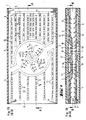
- FIGS. 1 and 2 show schematically a possible embodiment of a guide plate with feed, brake and rotation nozzles in a plan view and an idealized longitudinal section
- Figure 2 shows a section of a treatment line with devices connected in series, which are successively passed through by the discs to be treated. Corresponding elements are provided with the same reference symbols in both figures.
- a guide plate 1 for example made of polymethyl methacrylate (plexiglass), is shown with side borders 2.
- Independent supply channel systems 4, 5, 6 and 7 are introduced into the flat plate floor 3, the feed nozzles 11 being used via the channel systems 4 and 5, the brake nozzles 12 being used via the system 6 and the advantageous and present in the device shown via the system 7, but not mandatory mandatory rotary nozzles 13 can be supplied with, for example, aqueous medium.
- the individual rows of nozzles emanating from the channels are only shown schematically; the arrows in or on the Kanä However, len indicate the main direction in which the medium flowing out of the nozzles moves.
- the transport direction which is not specifically indicated, runs parallel to the longitudinal axis of the guide plate from left to right.
- an additional rotation area 8 is provided, in which it can be set in rotation during or after braking.
- the arrangement of the rotary nozzles 13 provided in this area advantageously follows lines which start radially from a common center, which essentially also corresponds to the center of the disc rotation. These lines can run straight, but are preferably curved, and advantageously follow circular lines, but also elliptical, parabolic or hyperbolic curve sections, the centers of curvature each lying in the intended direction of rotation.
- this line routing chosen for the arrangement of the rotary nozzles is also followed by the supply channel system 7, via which the finally released fluid is provided, although in principle also differently designed systems, for example in the form of ring channels, are not excluded are.
- At least 3, advantageously 4 to 10 such rows of rotary nozzles, starting from a common center and following the respectively chosen, preferably curved, lines are required.
- This arrangement preferably has rotational symmetry with respect to the common center.
- corresponding nozzles each lie on circles which are concentric with respect to the common center. It has proven particularly useful if the radius difference of successive circles does not remain constant, but instead decreases from the inside to the outside, so that the distance between adjacent nozzles from one another is ultimately reduced from the inside to the outside within a row of nozzles.
- the surface of the rotary region 8, which is equipped with rotary nozzles, corresponds favorably approximately to the surface of the disk-shaped workpiece being transported. It has proven to be advantageous, in particular with regard to the positional stability of the rotating disk, if the outermost rotary nozzles are arranged in such a way that they are still within the area covered by them during the rotational movement.
- the distance between the outermost rotary nozzles of a row of nozzles from the common center is favorably 60 to 95% of the disk radius.
- the rotary nozzles are expediently in each case in planes perpendicular to the plate bottom of the guide plate 1, wherein deviations of approximately ⁇ 5 ° from the exactly vertical orientation can still be tolerated. These planes intersect the lines along which the nozzles are arranged starting from the common center point at a right angle, with deviations of ⁇ 5 ° also still being permissible. If the rotary nozzles lie on straight lines, these planes are aligned essentially parallel. If the rows of the rotary nozzles form curved lines, for example circular lines, the planes intersect in an ideal alignment in a straight line which runs perpendicularly through the center of the curvature. In practice, however, the deviations from the ideal alignment mentioned are still permissible. It was also found that the washers at the rotation are particularly insensitive to deflections if the respective center of curvature lies outside the disk circumference.
- the rotary nozzles are inclined in the direction of rotation; the angle of inclination with respect to the plate bottom is 10 to 80 °, preferably 30 to 60 ° and advantageously approximately 45 °, as seen in the direction of rotation.
- a central feed line 9 can be provided, with the aid of which the particular, in particular aqueous, medium additionally also runs centrally from below and / or above the disc can be applied.
- the fronts between the feed and brake nozzles expediently do not run perpendicular to the direction of transport, but rather at an angle, whereby in each case those nozzles are advanced relative to the vertical front profile in which the exit direction of the fluid coexists the intended direction of rotation matches.
- the rotation area 8 does not necessarily have to be equipped with feed or brake nozzles, however, since experience shows that the amount of liquid released by the surrounding nozzles carries the disk, especially when aqueous media are preferred, even without the rotation nozzles already being in operation.
- overlapping areas are also not excluded, in which the front runs between the feed and brake nozzles through the rotation area, especially when disks with large diameters of, for example, about 20 cm and above are to be transported, braked and set in rotation.
- the fronts of the feed and brake nozzles advantageously run exactly or essentially parallel to one another.
- a straight front course for example directed at right angles or obliquely to the longitudinal axis of the guide plate, and a curved front course are possible, for example if a type of catch position with a circular or parabolic recessed central section of the brake nozzle system is provided.
- the longitudinal section along the line AA schematically shows an arrangement which according to the preferred embodiment is provided with a cover 10.
- the mutually independent supply channel systems 4, 6 and 7 are introduced, which the upper and lower feed nozzles 11 inclined in the transport direction, which runs from left to right, and the upper and lower feed inclinations inclined against the transport direction Brake nozzles 12 and the upper and lower rotary nozzles 13 inclined in the direction of rotation with fluid, in particular supply aqueous medium.
- An approximately mirror-image arrangement of the nozzle systems, in particular the brake nozzles, in the cover and in the base of the plate has proven itself, although other arrangements, for example zipper-like alternating arrangements, are also not excluded.
- the channels in the cover and in the plate base can also be offset from one another, or the nozzles can be arranged at different angles of inclination.
- constriction 14 is advantageously produced via a beveling of the cover on the input and output sides until the intended distance from the plate bottom is reached, which typically corresponds to approximately 3 to 5 mm.
- the deviation from the horizontal is appropriately kept small in the area of the bevel; In most cases, values of up to approximately 10 ° have proven successful, the edges possibly being rounded in the transition regions from and to the horizontal.
- control systems are preferably provided, in which control pulses triggered by the continuous disk advantageously activate the required nozzle system.
- a pane in particular a semiconductor pane
- the feed nozzles 11 charged via the supply duct system 4 are initially set to work, in order to allow the pane to advance into the interior.
- the brake nozzles 12 are likewise put into operation via the supply channel system 6, so that a flow opposite to the fluid flow formed by the feed nozzles is formed.
- the rotary nozzles 13 are switched on and the disk begins to rotate with increasing speed.
- rotation speeds of approximately 60 rpm could be achieved for silicon wafers with a diameter of approximately 20 cm. Water was used as the fluid, the pressure was about 450 kPa.
- the fluid supply is interrupted by the rotation nozzles and the brake nozzles, while the feed nozzles that are not yet in operation are put into operation in the guide plate, so that all feed nozzles, that is to say those fed via the supply duct systems 4 and 5, are in operation .
- the disc sits. thereby moving again in the transport direction and finally leaving the guide plate.
- the fluid supply via the supply channel system 5 can then expediently be stopped again via a sensor control, while another disk can be inserted and transported on the input side.
- the control can also be carried out manually, for example in trial operation or when optimizing the operating parameters.
- At least one liquid retainer to be traversed by the disks is provided on the device on the input and / or output side can be seen, for example in order to be able to remove any residues of liquids, reagents or particles still adhering from the previous treatment stage, or to keep the risk of carryover of fluid residues out of the device into the subsequent treatment stage.
- the retention effect can be achieved, for example, with the aid of liquid curtains or jets which have the corresponding width in order to be able to act on the entire pane surface which is passing through. The retention effect is caused by the relative speed between the pane passing through and the liquid curtain or liquid jet.
- several liquid retainers connected in series can also be provided. Such liquid retainers are preferably charged with the medium used in each case in the device.
- Such combinations of guide plate with retainer and drying zone can in turn be combined with one another or connected in series, so that ultimately entire treatment lines can be built, in which the disks are loaded with changing fluids one after the other Run through devices and thus can be etched, rinsed, cleaned, or subjected to other wet chemical treatment steps, for example.
- FIG. 2 shows a possible section from such a treatment line. It initially shows a starting position 15, in which the disks can be provided in a process tray, for example, and can be removed, for example, by means of water or air nozzles. The disks then enter the first treatment station 16, which is located, for example, in a tub 17, which is only indicated schematically and serves to collect the amount of liquid escaping in this station. The disc is first brought up to speed with the aid of the feed nozzles 18 and then enters the guide plate 1 of the actual device, in which it is transported, braked, rotated and moved on in the manner already explained.
- the disk After leaving the guide plate 1, the disk receives a further movement impulse from the discharge nozzles 19 and then enters the second treatment station 22 through the liquid retainer 20 and through the separation zone 21, which is designed, for example, as a drying zone, and which is basically constructed analogously to the first, and can be loaded with the same, but also with a different fluid.
- the separation zone 21 which is designed, for example, as a drying zone, and which is basically constructed analogously to the first, and can be loaded with the same, but also with a different fluid.
- any number of other treatment stations can be connected.
- different aqueous media can be used with particular advantage as fluids, such as pure water, acidic solutions, surfactant-containing solutions or oxidizing solutions.
- treatment steps such as washing, rinsing or neutralization processes can also be carried out in the separation zones 21.
- Devices of this type are therefore particularly suitable for processes for the wet chemical surface treatment of disk-shaped workpieces, in particular semiconductor wafers, in which one or more liquid phases are brought into action on the disk surface and the disks are subjected to at least one transport process by means of fluid media.
- a device according to the invention can only be used in one or in separate treatment steps, in which case the fluid used is the fluid which should also act on the wafer surface in the respective process step.
- the fluid used is the fluid which should also act on the wafer surface in the respective process step.
- several, at least two, devices connected in series are used in such methods in the manner described above.
- Aqueous media are preferably used as fluids, specifically all solutions currently known for the wet-chemical surface treatment of semiconductor wafers in the course of the final cleaning process can be used.
- the particular advantage here is that an aqueous medium of a certain composition is always used in a treatment station, so that contamination by chemical changes can be ruled out, the risk of carryover to subsequent treatment stations is low, and also the treatment of the aqueous media and possible reuse or a cycle within the treatment station is possible.
- no mechanical contacts or transport processes with mechanically moving parts are required, just as little as for braking and rotating the disc.
- the hydraulic components and drive elements required for operation are low-wear and the required pressure ranges can be easily mastered, so that, in addition to purer products, in particular semiconductor wafers, mechanical service steps and devices can also achieve shorter service lives.
Landscapes
- Physics & Mathematics (AREA)
- Engineering & Computer Science (AREA)
- Fluid Mechanics (AREA)
- Mechanical Engineering (AREA)
- Cleaning Or Drying Semiconductors (AREA)
- Weting (AREA)
Applications Claiming Priority (2)
| Application Number | Priority Date | Filing Date | Title |
|---|---|---|---|
| DE3923405A DE3923405A1 (de) | 1989-07-14 | 1989-07-14 | Vorrichtung zum transportieren und positionieren von scheibenfoermigen werkstuecken, insbesondere halbleiterscheiben, und verfahren zur nasschemischen oberflaechenbehandlung derselben |
| DE3923405 | 1989-07-14 |
Publications (2)
| Publication Number | Publication Date |
|---|---|
| EP0408021A1 true EP0408021A1 (fr) | 1991-01-16 |
| EP0408021B1 EP0408021B1 (fr) | 1993-10-06 |
Family
ID=6385088
Family Applications (1)
| Application Number | Title | Priority Date | Filing Date |
|---|---|---|---|
| EP90113307A Expired - Lifetime EP0408021B1 (fr) | 1989-07-14 | 1990-07-12 | Dispositif pour transporter et positioner des pièces à usiner en forme de disque, notamment des disques semi-conducteurs et procédé pour le traitement chimique en surface, par voie humide de celles-ci |
Country Status (5)
| Country | Link |
|---|---|
| US (1) | US5108513A (fr) |
| EP (1) | EP0408021B1 (fr) |
| JP (1) | JPH0744165B2 (fr) |
| KR (1) | KR970000007B1 (fr) |
| DE (2) | DE3923405A1 (fr) |
Cited By (4)
| Publication number | Priority date | Publication date | Assignee | Title |
|---|---|---|---|---|
| JPH04212421A (ja) * | 1990-06-15 | 1992-08-04 | Matoritsukusu:Kk | 半導体ウェーハの表面処理装置 |
| US5788425A (en) * | 1992-07-15 | 1998-08-04 | Imation Corp. | Flexible system for handling articles |
| US6412500B1 (en) | 1999-01-14 | 2002-07-02 | WACKER SILTRONIC GESELLSCHAFT FüR HALBLEITERMATERIALIEN AG | Device and method for cleaning semiconductor wafers |
| TWI562268B (en) * | 2012-04-04 | 2016-12-11 | Rena Gmbh | Apparatus and method for the transport on a liquid |
Families Citing this family (32)
| Publication number | Priority date | Publication date | Assignee | Title |
|---|---|---|---|---|
| EP0747931B1 (fr) * | 1990-11-16 | 2000-07-12 | Kabushiki Kaisha Watanabe Shoko | Méthode de transport d'objet à base de forme plate |
| DE4100526A1 (de) * | 1991-01-10 | 1992-07-16 | Wacker Chemitronic | Vorrichtung und verfahren zum automatischen vereinzeln von gestapelten scheiben |
| US5344365A (en) * | 1993-09-14 | 1994-09-06 | Sematech, Inc. | Integrated building and conveying structure for manufacturing under ultraclean conditions |
| JP3331256B2 (ja) * | 1994-05-10 | 2002-10-07 | バイエルコーポレーション | 試験片表裏判別手段 |
| US5762084A (en) * | 1994-07-15 | 1998-06-09 | Ontrak Systems, Inc. | Megasonic bath |
| US5745946A (en) * | 1994-07-15 | 1998-05-05 | Ontrak Systems, Inc. | Substrate processing system |
| US5548505A (en) * | 1994-07-15 | 1996-08-20 | Oktrak Systems, Inc. | Scrubber control system |
| DE19628620A1 (de) * | 1995-08-08 | 1998-01-29 | Heidelberger Druckmasch Ag | Leiteinrichtung für einen frisch bedruckten Bogen |
| US5924154A (en) * | 1996-08-29 | 1999-07-20 | Ontrak Systems, Inc. | Brush assembly apparatus |
| NL1011487C2 (nl) | 1999-03-08 | 2000-09-18 | Koninkl Philips Electronics Nv | Werkwijze en inrichting voor het roteren van een wafer. |
| US6818604B2 (en) | 2001-10-04 | 2004-11-16 | Speedfam-Ipec Corporation | System and method for cleaning workpieces |
| US20030168174A1 (en) | 2002-03-08 | 2003-09-11 | Foree Michael Todd | Gas cushion susceptor system |
| US6883250B1 (en) * | 2003-11-04 | 2005-04-26 | Asm America, Inc. | Non-contact cool-down station for wafers |
| US8229585B2 (en) | 2005-09-18 | 2012-07-24 | Flitsch Frederick A | Methods and apparatus for vertically orienting substrate processing tools in a clean space |
| US7513822B2 (en) | 2005-06-18 | 2009-04-07 | Flitsch Frederick A | Method and apparatus for a cleanspace fabricator |
| US11024527B2 (en) | 2005-06-18 | 2021-06-01 | Frederick A. Flitsch | Methods and apparatus for novel fabricators with Cleanspace |
| US9059227B2 (en) | 2005-06-18 | 2015-06-16 | Futrfab, Inc. | Methods and apparatus for vertically orienting substrate processing tools in a clean space |
| US9159592B2 (en) | 2005-06-18 | 2015-10-13 | Futrfab, Inc. | Method and apparatus for an automated tool handling system for a multilevel cleanspace fabricator |
| US10651063B2 (en) | 2005-06-18 | 2020-05-12 | Frederick A. Flitsch | Methods of prototyping and manufacturing with cleanspace fabricators |
| US9457442B2 (en) * | 2005-06-18 | 2016-10-04 | Futrfab, Inc. | Method and apparatus to support process tool modules in a cleanspace fabricator |
| US10627809B2 (en) | 2005-06-18 | 2020-04-21 | Frederick A. Flitsch | Multilevel fabricators |
| US9339900B2 (en) | 2005-08-18 | 2016-05-17 | Futrfab, Inc. | Apparatus to support a cleanspace fabricator |
| US7467024B2 (en) * | 2005-08-26 | 2008-12-16 | Flitsch Frederick A | Method and apparatus for an elevator system for a multilevel cleanspace fabricator |
| JP4594241B2 (ja) | 2006-01-06 | 2010-12-08 | 東京エレクトロン株式会社 | 基板搬送装置、基板搬送方法及びコンピュータプログラム |
| DE202006018111U1 (de) * | 2006-07-25 | 2007-02-08 | Lang, Marcus | Vorrichtung zum beschleunigten nasschemischen Behandeln von Oberflächen |
| US9355880B2 (en) | 2008-06-19 | 2016-05-31 | Rena Gmbh | Method and apparatus for the transporting of objects |
| KR101588440B1 (ko) * | 2008-07-10 | 2016-01-25 | 오일레스고교 가부시키가이샤 | 선회류 형성체 및 비접촉 반송 장치 |
| JP5406852B2 (ja) * | 2008-11-18 | 2014-02-05 | オイレス工業株式会社 | 非接触搬送装置 |
| CN101875036A (zh) * | 2009-04-30 | 2010-11-03 | 深圳富泰宏精密工业有限公司 | 转动装置 |
| US8834073B2 (en) * | 2010-10-29 | 2014-09-16 | Corning Incorporated | Transport apparatus having a measuring system and methods therefor |
| US9698042B1 (en) | 2016-07-22 | 2017-07-04 | Lam Research Corporation | Wafer centering in pocket to improve azimuthal thickness uniformity at wafer edge |
| JP7437186B2 (ja) * | 2020-02-26 | 2024-02-22 | Jswアクティナシステム株式会社 | 浮上搬送装置、及びレーザ処理装置 |
Citations (2)
| Publication number | Priority date | Publication date | Assignee | Title |
|---|---|---|---|---|
| US3797889A (en) * | 1971-12-30 | 1974-03-19 | Texas Instruments Inc | Workpiece alignment system |
| US4618292A (en) * | 1977-02-28 | 1986-10-21 | International Business Machines Corporation | Controls for semiconductor wafer orientor |
Family Cites Families (5)
| Publication number | Priority date | Publication date | Assignee | Title |
|---|---|---|---|---|
| US3215238A (en) * | 1963-10-30 | 1965-11-02 | Rca Corp | Orienting articles of manufacture |
| US3976329A (en) * | 1974-09-09 | 1976-08-24 | Texas Instruments Incorporated | Vacuum braking system for semiconductor wafers |
| US4242038A (en) * | 1979-06-29 | 1980-12-30 | International Business Machines Corporation | Wafer orienting apparatus |
| US4348139A (en) * | 1980-04-30 | 1982-09-07 | International Business Machines Corp. | Gas film wafer transportation system |
| JPS63225028A (ja) * | 1987-03-16 | 1988-09-20 | Hitachi Ltd | 搬送装置 |
-
1989
- 1989-07-14 DE DE3923405A patent/DE3923405A1/de not_active Withdrawn
-
1990
- 1990-05-03 US US07/518,580 patent/US5108513A/en not_active Expired - Fee Related
- 1990-05-17 JP JP2125602A patent/JPH0744165B2/ja not_active Expired - Lifetime
- 1990-07-11 KR KR90010491A patent/KR970000007B1/ko not_active Expired - Fee Related
- 1990-07-12 DE DE90113307T patent/DE59002987D1/de not_active Expired - Fee Related
- 1990-07-12 EP EP90113307A patent/EP0408021B1/fr not_active Expired - Lifetime
Patent Citations (2)
| Publication number | Priority date | Publication date | Assignee | Title |
|---|---|---|---|---|
| US3797889A (en) * | 1971-12-30 | 1974-03-19 | Texas Instruments Inc | Workpiece alignment system |
| US4618292A (en) * | 1977-02-28 | 1986-10-21 | International Business Machines Corporation | Controls for semiconductor wafer orientor |
Cited By (4)
| Publication number | Priority date | Publication date | Assignee | Title |
|---|---|---|---|---|
| JPH04212421A (ja) * | 1990-06-15 | 1992-08-04 | Matoritsukusu:Kk | 半導体ウェーハの表面処理装置 |
| US5788425A (en) * | 1992-07-15 | 1998-08-04 | Imation Corp. | Flexible system for handling articles |
| US6412500B1 (en) | 1999-01-14 | 2002-07-02 | WACKER SILTRONIC GESELLSCHAFT FüR HALBLEITERMATERIALIEN AG | Device and method for cleaning semiconductor wafers |
| TWI562268B (en) * | 2012-04-04 | 2016-12-11 | Rena Gmbh | Apparatus and method for the transport on a liquid |
Also Published As
| Publication number | Publication date |
|---|---|
| EP0408021B1 (fr) | 1993-10-06 |
| US5108513A (en) | 1992-04-28 |
| DE3923405A1 (de) | 1991-01-24 |
| JPH0355836A (ja) | 1991-03-11 |
| JPH0744165B2 (ja) | 1995-05-15 |
| DE59002987D1 (de) | 1993-11-11 |
| KR970000007B1 (en) | 1997-01-04 |
Similar Documents
| Publication | Publication Date | Title |
|---|---|---|
| EP0408021B1 (fr) | Dispositif pour transporter et positioner des pièces à usiner en forme de disque, notamment des disques semi-conducteurs et procédé pour le traitement chimique en surface, par voie humide de celles-ci | |
| EP0494673B1 (fr) | Dispositif et procédés pour séparer automatiquement des disques empilés | |
| DE19906805B4 (de) | Vorrichtung und Verfahren zum Transportieren von zu bearbeitenden Substraten | |
| DE3909669C2 (fr) | ||
| EP1372186B1 (fr) | Dispositif de traitement de plaquettes | |
| EP0316296B1 (fr) | Support pour objets en forme de disque et dispositif de décapage de plaquettes de silicium avec un tel support | |
| DE19781822B4 (de) | Reinigungsstation zur Verwendung bei einem System zum Reinigen, Spülen und Trocknen von Halbleiterscheiben | |
| CH670416A5 (fr) | ||
| EP0497104B1 (fr) | Magasin pour contenir des pièces en forme de disques, en particulier des disques semi-conducteurs, dans un traitement de surface chimique en bains liquides | |
| DE2931308A1 (de) | Oberflaechenbehandlungs-einrichtung | |
| WO1999004416A1 (fr) | Procede et dispositif pour le traitement de substrats plans, en particulier de pastilles de silicium (tranches) pour la fabrication de composants microelectroniques | |
| DE69022659T2 (de) | Kontinuierliches Frittiergerät unter Vakuum. | |
| DE4038587A1 (de) | Transportvorrichtung fuer substrate | |
| DE69209420T2 (de) | Verfahren und Gerät zum Ausrichten von Gegenständen | |
| WO2003089191A1 (fr) | Procede et dispositif de polissage chimico-mecanique de pieces | |
| EP0976146B1 (fr) | Dispositif de transport de substrats a travers une installation de traitement de substrats | |
| DE3820591A1 (de) | Vorrichtung zum nassaetzen von duennen filmen | |
| DE102021208695B4 (de) | Bearbeitungsvorrichtung mit einer zuführeinheit zum schnellen beabstanden eines wafers von einer haltefläche | |
| DE10200525A1 (de) | Vorrichtung und Verfahren zum Behandeln von scheibenförmigen Substraten | |
| DE10100428B4 (de) | Verfahren und Vorrichtung zum Kühlen von Substraten | |
| DE3826925A1 (de) | Einrichtung zur handhabung und behandlung kontaminationsempfindlicher gegenstaende, wie halbleiterteile (wafers) oder aehnlicher produkte | |
| DE69206062T2 (de) | Ätztrommel für Scheiben und automatische Umladevorrichtung für Scheiben. | |
| DE10212420A1 (de) | Einrichtung zur Aufnahme eines Wafers | |
| EP1126505A2 (fr) | Méthode et dispositif pour le nettoyage et l'attaque chimique de substrats individuels en forme de disque | |
| DE102004057754B4 (de) | Verfahren und Vorrichtung zum Behandeln von ein Innenloch aufweisenden Substratscheiben |
Legal Events
| Date | Code | Title | Description |
|---|---|---|---|
| PUAI | Public reference made under article 153(3) epc to a published international application that has entered the european phase |
Free format text: ORIGINAL CODE: 0009012 |
|
| 17P | Request for examination filed |
Effective date: 19900712 |
|
| AK | Designated contracting states |
Kind code of ref document: A1 Designated state(s): DE GB IT |
|
| 17Q | First examination report despatched |
Effective date: 19921029 |
|
| ITF | It: translation for a ep patent filed | ||
| GRAA | (expected) grant |
Free format text: ORIGINAL CODE: 0009210 |
|
| AK | Designated contracting states |
Kind code of ref document: B1 Designated state(s): DE GB IT |
|
| REF | Corresponds to: |
Ref document number: 59002987 Country of ref document: DE Date of ref document: 19931111 |
|
| GBT | Gb: translation of ep patent filed (gb section 77(6)(a)/1977) |
Effective date: 19931111 |
|
| PLBE | No opposition filed within time limit |
Free format text: ORIGINAL CODE: 0009261 |
|
| STAA | Information on the status of an ep patent application or granted ep patent |
Free format text: STATUS: NO OPPOSITION FILED WITHIN TIME LIMIT |
|
| 26N | No opposition filed | ||
| REG | Reference to a national code |
Ref country code: GB Ref legal event code: 732E |
|
| PGFP | Annual fee paid to national office [announced via postgrant information from national office to epo] |
Ref country code: DE Payment date: 20010620 Year of fee payment: 12 |
|
| PGFP | Annual fee paid to national office [announced via postgrant information from national office to epo] |
Ref country code: GB Payment date: 20010621 Year of fee payment: 12 |
|
| REG | Reference to a national code |
Ref country code: GB Ref legal event code: IF02 |
|
| PG25 | Lapsed in a contracting state [announced via postgrant information from national office to epo] |
Ref country code: GB Free format text: LAPSE BECAUSE OF NON-PAYMENT OF DUE FEES Effective date: 20020712 |
|
| PG25 | Lapsed in a contracting state [announced via postgrant information from national office to epo] |
Ref country code: DE Free format text: LAPSE BECAUSE OF NON-PAYMENT OF DUE FEES Effective date: 20030201 |
|
| GBPC | Gb: european patent ceased through non-payment of renewal fee |
Effective date: 20020712 |
|
| PG25 | Lapsed in a contracting state [announced via postgrant information from national office to epo] |
Ref country code: IT Free format text: LAPSE BECAUSE OF NON-PAYMENT OF DUE FEES;WARNING: LAPSES OF ITALIAN PATENTS WITH EFFECTIVE DATE BEFORE 2007 MAY HAVE OCCURRED AT ANY TIME BEFORE 2007. THE CORRECT EFFECTIVE DATE MAY BE DIFFERENT FROM THE ONE RECORDED. Effective date: 20050712 |