EP0408061B1 - Concentrateur et commutateur de paquets - Google Patents
Concentrateur et commutateur de paquets Download PDFInfo
- Publication number
- EP0408061B1 EP0408061B1 EP90113462A EP90113462A EP0408061B1 EP 0408061 B1 EP0408061 B1 EP 0408061B1 EP 90113462 A EP90113462 A EP 90113462A EP 90113462 A EP90113462 A EP 90113462A EP 0408061 B1 EP0408061 B1 EP 0408061B1
- Authority
- EP
- European Patent Office
- Prior art keywords
- packet
- call
- concentrator
- lcn
- switching equipment
- Prior art date
- Legal status (The legal status is an assumption and is not a legal conclusion. Google has not performed a legal analysis and makes no representation as to the accuracy of the status listed.)
- Expired - Lifetime
Links
- 238000004891 communication Methods 0.000 claims description 18
- 238000000034 method Methods 0.000 claims description 16
- 238000012545 processing Methods 0.000 claims description 15
- 238000006243 chemical reaction Methods 0.000 claims description 8
- 230000000977 initiatory effect Effects 0.000 claims 2
- 230000005540 biological transmission Effects 0.000 claims 1
- 238000010586 diagram Methods 0.000 description 16
- 230000006870 function Effects 0.000 description 7
- 230000015654 memory Effects 0.000 description 7
- 108010076504 Protein Sorting Signals Proteins 0.000 description 4
- 230000015572 biosynthetic process Effects 0.000 description 3
- 239000012141 concentrate Substances 0.000 description 3
- 230000004075 alteration Effects 0.000 description 2
- 230000008901 benefit Effects 0.000 description 2
- 238000005516 engineering process Methods 0.000 description 2
- 239000000203 mixture Substances 0.000 description 2
- 238000012986 modification Methods 0.000 description 2
- 230000004048 modification Effects 0.000 description 2
- 230000008569 process Effects 0.000 description 2
- 238000012546 transfer Methods 0.000 description 2
- 230000009286 beneficial effect Effects 0.000 description 1
- 238000012423 maintenance Methods 0.000 description 1
- 230000014759 maintenance of location Effects 0.000 description 1
- 230000003287 optical effect Effects 0.000 description 1
- 238000003860 storage Methods 0.000 description 1
Images


Classifications
-
- H—ELECTRICITY
- H04—ELECTRIC COMMUNICATION TECHNIQUE
- H04L—TRANSMISSION OF DIGITAL INFORMATION, e.g. TELEGRAPHIC COMMUNICATION
- H04L49/00—Packet switching elements
- H04L49/30—Peripheral units, e.g. input or output ports
- H04L49/3009—Header conversion, routing tables or routing tags
-
- H—ELECTRICITY
- H04—ELECTRIC COMMUNICATION TECHNIQUE
- H04L—TRANSMISSION OF DIGITAL INFORMATION, e.g. TELEGRAPHIC COMMUNICATION
- H04L49/00—Packet switching elements
- H04L49/25—Routing or path finding in a switch fabric
- H04L49/253—Routing or path finding in a switch fabric using establishment or release of connections between ports
- H04L49/254—Centralised controller, i.e. arbitration or scheduling
-
- H—ELECTRICITY
- H04—ELECTRIC COMMUNICATION TECHNIQUE
- H04L—TRANSMISSION OF DIGITAL INFORMATION, e.g. TELEGRAPHIC COMMUNICATION
- H04L49/00—Packet switching elements
- H04L49/10—Packet switching elements characterised by the switching fabric construction
- H04L49/103—Packet switching elements characterised by the switching fabric construction using a shared central buffer; using a shared memory
-
- H—ELECTRICITY
- H04—ELECTRIC COMMUNICATION TECHNIQUE
- H04L—TRANSMISSION OF DIGITAL INFORMATION, e.g. TELEGRAPHIC COMMUNICATION
- H04L49/00—Packet switching elements
- H04L49/30—Peripheral units, e.g. input or output ports
-
- H—ELECTRICITY
- H04—ELECTRIC COMMUNICATION TECHNIQUE
- H04L—TRANSMISSION OF DIGITAL INFORMATION, e.g. TELEGRAPHIC COMMUNICATION
- H04L49/00—Packet switching elements
- H04L49/50—Overload detection or protection within a single switching element
Definitions
- the present invention relates to a method and an apparatus for concentrating calls in a communication network, particularily in a packet network.
- Typical examples of a multiplexing system for packet switching equipment are described in the CCITT RED BOOK X.25 (a user-network interface) and X.75 (a network-network interface). These examples are also briefly described on pp.100-102 of Packet Switching Technology and Its Application (the Institute of Electronic, Information, and Communication Engineers).
- pp.100-102 of Packet Switching Technology and Its Application the Institute of Electronic, Information, and Communication Engineers.
- For a conventional packet concentrating system there are known two different concentrating systems as described on pp.88 and 89, and pp.102-105 of the above-mentioned Packet Switching Technology and Its Application .
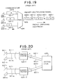
- the first concentrating system is shown, for example, in Figure 20 and has a packet multiplexer (PMX) 604 in which data 601-1 to 601-3 is sent from lines connected to a plurality of non-packet mode terminals (NPT) 600-1 to 600-3. The data is packed by the PMX and then sent on the same line 605 with terminal identifications in the labels of the packets 606-1 to 608-n.
- PMX packet multiplexer
- NPT non-packet mode terminals
- the second concentrating system is shown, for example, in Figure 21 wherein a packet concentrator 620 (comprised of elements 620-1 to 620-l) and a packet distributor 630 operate so that the output from each concentrator element is provided to the distributor 630 through a number n of output lines (612-1 to 612-n) which is less than a number m of input packet lines (611-1 to 611-m).
- a logical channel for the terminal data must be set link by link and different logical channels are set between a terminal 610 and the packet concentrator 620 and between the packet concentrator 620 and packet distributor 630.
- the concentrator since an individual call is set link-by-link, it becomes necessary for the concentrator to also switch logical channels. Consequently, the concentrator is required to administrate logical channels, i.e., to have a capability to terminate a control signal and execute call processing. It becomes impossible for any switching equipment which is placed higher than the concentrator to identify the sender of information being transmitted because the logical channel number is changed by the time that switching equipment receives the data signal.
- the concentrator besides completing its primary concentrating tasks, is therefore required to also execute extensive controlling processes with regard to the sender such as a tariff control and others.
- the individual packet switching equipment needs the capability of processing functions to terminate a call control signal as a concentrating node for concentrating multiplexed lines by logical channel numbers. This extensive control processing becomes a substantial problem to be solved with the continued expansion of packet line converging and multiplexing of communication media.
- the conventional system in which a packet switching equipment is arranged with such a concentrating node is costly, and raises a serious problem in that respect.
- a packet switching system of the type shown in Figure 21 is also disclosed in DE-A-3 210 462.
- This system uses two different logic channel numbers to identify communication between a terminal and a concentrator on the one hand and between the concentrator and switching equipment on the other hand for each call.
- the same document also discloses another system, where only one logic channel number is used for the entire communication relating to one call between a terminal and the switching equipment via a concentrator.
- a certain set of logic channel numbers is preallocated to each terminal.
- the logic channel number of the packet is compared with each logic channel number preallocated to each of the terminals connected to said concentrator in order to determine to which terminal the packet has to be transmitted.
- a packet switching system comprising a concentrator for concentrating multiplexed packet lines without switching logical channels reduces call processing at the concentrator.
- the concentrator is provided in a packet network in which a switching equipment, a concentrator, and terminals are hierarchically arranged.
- the concentrator concentrates multiplexed packet lines without switching logical channels.
- the same logical channel number (LCN) is used between a terminal and a concentrator as well as between a concentrator and the switching equipment in a connection of a call.
- the concentrator In order to transmit a down packet from the switching equipment to a concentrator in a line in which an up packet from the terminal having the same LCN as the LCN of said packet is inputted, the concentrator has a means for storing an input line number corresponding to the LCN, and a means for inserting the above-mentioned line number into the data transmitted between the concentrator and the switching equipment as a packet.
- the switching equipment has a means for charging by each line the number of communication packets counted according to the LCN by use of the line number inserted into the above-mentioned packet.
- the line number stored in accordance with the LCN in the above-mentioned concentrator is read by each LCN when the down packet from the switching equipment terminates.
- the concentrator sends the packet to a terminal line to which said LCN is connected.
- the concentrator inserts a line number of the packet received into an up packet, and the switching equipment inserts a line number stored when the up packet is received. Then, the packet is sent by the concentrator to a terminal line to which the terminal of that LCN is connected, while a tariff control can be executed by the switching equipment by the line number.
- a packet switching system and method can be provided which includes a concentrator which avoids extensive call processing therein for a far less costly system that can readily adapt to the expansion of packet line converging and expansion of communication media.
- Another benefit is the provision of a packet network which allows a switching equipment placed higher than a concentrator to execute general call processing such as tariff control and other processing steps.
- the Embodiment is a system in which a corresponding line for a down signal from a higher packet switching equipment is identified without terminating signals in a packet concentrator, and which has a storing function for an LCN and a line number in a packet concentrator.
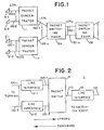
- FIG. 1 An embodiment of a packet network comprising the present invention is shown in Fig. 1.
- the network has a hierarchical structure comprising a plurality of packet concentrators 1 (1-1 to 1-n) for concentrating each of a plurality of packet lines 100 (100-1 to 100-l) from each of a plurality of terminals 3 (3-1 to 3-l) at a packet line 120 (120-1 to 120-n).
- the packet line 120 is connected to the packet concentrator 1 and packet switching equipment 2 (2A and 2B) which distribute transit packet line 130 (130-1 to 130-m) from switching equipment 2A to the other packet switching equipment 2B.
- a logical channel (LCN1) between the packet concentrator 1 and the packet switching equipment 2A is the same as the logical channel between the terminal 3 and the packet concentrator 1, but is different from a logical channel (LCN2) between the packet switching equipment 2A and the packet switching equipment 2B.
- an LCN is switched in the packet switching equipment 2, but the LCN is not switched in the packet concentrator 1.
- the packet concentrator 1 comprises a packet switch 11 for concentrating packet lines 100-1 to 100-l connected to packet terminals 3 and line interfaces 12-1 to 12-l for terminating each line, and a line interface 13 connected to the packet line 120 which in turn is connected to the packet switching equipment 2.
- the packet concentrator 1 according to this embodiment concentrates a plurality of lines (100-1 to 100-l) connected to the terminals 3 on a packet line 120 connected to the higher switching equipment 2A.
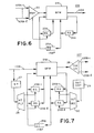
- Fig. 5 is a diagram showing the circuit structure of the packet switch 11, comprising an up switch 106 for processing a packet from the terminal 3 to the switching equipment 2A and a down switch 107 for processing a packet from the switching equipment 2A to the terminal 3.
- the details of the up switch 106 are shown in Fig. 6, and the details of the down switch 107, in Fig. 7, respectively.
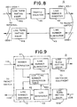
- the circuit formation of line interfaces 12 and 13 in the concentrator 1 are shown in Figs. 8 and 9. As shown in Fig.
- the packet switching equipment 2 comprises a packet switch 302 for distributing packets, line interfaces 300 (300-1 to 300-m) for terminating lines 120-1 to 120-n connected to the packet concentrator 1, line interfaces 301 (301-1 to 301-m) that are connected to transit packet lines 130-1 to 130-m, and a CP (Call Processing) module 303 for call processing, maintenance and administration.
- a packet switch 302 for distributing packets
- line interfaces 300 300-1 to 300-m
- line interfaces 301 for terminating lines 120-1 to 120-n connected to the packet concentrator 1
- line interfaces 301 301-1 to 301-m
- CP Call Processing
- the packet concentrator 1 has a feature that it communicates a packet from the switching equipment to the terminals with the same logical channel number LCN.
- a function is provided for sending a down packet inputted from the packet switching equipment 2A to the proper inputted line (one of the lines 100) of a terminal 3 by storing a line number corresponding to the LCN.
- Each packet switch 11 is based on an ATM (Asynchronous Transfer Mode) switch, a memory switch introduced, for example in a paper IEICE Technical Report SSE88-56 (A study on the ATM switching architecture).
- the entire structure of the packet switch 11 comprises the up switch 106 and the down switch 107.
- the up switch 106 sends packets received from a plurality of lines 105A (105A-1 to 105A-1) connected to terminals 3, to a line 110A connected to the packet switching equipment, while the down switch 107 sends packets received from a line 110B connected to the packet switching equipment 2A to one of the lines 105B (105B-1 to 105B-l) connected to the terminals.
- the up switch 106 comprises a multiplexer (MUX) 22 for multiplexing a plurality of packet lines 105A-1 to 105A-l, a shared buffer memory (BFM) 21A for temporarily storing packets, an idle address buffer (IABF) 25A which is an FIFO for indicating idle buffer addresses in the BFM, a write address register (WA) 23A for a queuing buffer for an output line (only one line in the up switch), and a read address register (RA) 24A.
- MUX multiplexer
- BFM shared buffer memory
- IABF idle address buffer
- WA write address register
- RA read address register
- the down switch 107 comprises, in addition to a BFM 21B, an IABF 25B, write address registers (WA) 23B-1 to 23B-l, and read address registers (RA) 24B-1 to 24B-l, a routing detector (RT) 27, a routing filter (RTFLT) 28 for selecting one of the write address registers (WA) 23B-1 to 23B-l, an output control counter (OUTCNT) 29 for specifying output line numbers periodically (1 to l, and an output decoder (OUTDEC) 30 for selecting one of the read address registers (RA) 24B-1 to 24B-l.
- RT routing detector
- RTFLT routing filter
- OUTCNT output control counter
- OUTDEC output decoder
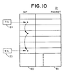
- the shared buffer memory BFM21 (21A and 21B) comprises a next pointer (NP) area 80 and a packet information area 81, as shown in Fig. 10, and each packet is chained at its address by the NP per each output line, respectively.
- the top address of the chain is set in a read address register RA24 and the last address of the chain is set in a write address register WA23.
- a hunt idle buffer address is set in the next pointer NP area 80 of the address indicated by the WA23, and when packets are sent, the packet information 81 indicated by RA24 is read.
- Fig. 8 is a schematic diagram showing the line interface 12 of lines 100 to which terminals 3 are connected.
- the upward circuit has an optical electrical signal converter (not shown), a serial-parallel converter (not shown), a line terminating equipment 41A for processing packet line synchronization and other normal terminating functions, a traffic counter 45 for counting packet numbers per logical channel number, and a line number inserter 42 for inserting into a packet header a line number assigned for the line interface.
- the downward circuit has a line number eliminator 43 for eliminating the line number in the packet header, and line terminating equipment 41B the same as the above-mentioned.
- Fig. 9 is a schematic diagram illustrating the circuit formation of a line interface 13 of the lines 120 connected to the switching equipment 2A.
- the upward circuit comprises a header separator 47 for separating header information, a line number eliminator 52 for eliminating a line number in a packet header, and a line terminating equipment 50A while the downward circuit comprises a line terminating equipment 50B, an LCN separator 49 for separating an LCN in a packet header, and a line number inserter 51 for inserting a line number in a packet header.
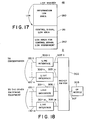
- an LCN-to-line number conversion table 48A is provided, the arrangement of which is shown in Fig. 17. In this table, a line number is written for the LCN in the header information separated by the header separator 47 for the up packet, and a line number is read in accordance with the LCN separated by the LCN separator 49 for the down packet.
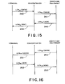
- a system is thus provided whereby a down packet (the packet being sent to the terminal 3 from the packet switching equipment 2A through the packet concentrator 1) has the same logical channel as an up packet (the packet being sent to the packet switching equipment 2A from the terminal 3 through the packet concentrator 1). How the signal is outputted to the same line from which said up packet is inputted will subsequently be described with reference to Fig. 11 to Fig. 16 which show the signal sequence diagrams.
- LCN For a particular logical channel number (LCN), three different kinds of LCN's are used from the time a call is originated until it is released. These are a packet LCN for transferring user information; an LCN for a signal control packet for a call setup/release and other normal set up and release functions; and, an LCN for a packet of requirement signal for assignment of a control signal at the time of terminal registration.
- LCN logical channel number
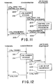
- Fig. 11 is a diagram showing a signal sequence for terminal registration.
- the terminal 3 sends a packet of requirement signal for LCN assignment for signal control 200 to the concentrator 1 using the LCN 0 for assigning a control LCN predetermined by the packet switching equipment 2A.
- the composition of a packet in the line 100 between the terminal 3 and the packet concentrator 1 is shown in Fig. 3.
- the packet is separated for header information and user information, and the header information includes the LCN (LCN 0 ) and the user information includes a signal classification SIG (requirement signal for LCN assignment of control signal).
- LCN LCN 0
- SIG signal classification SIG
- the line interface 12 When this packet is inputted to the line interface 12 in Fig. 2, the line interface 12 inserts a line number LN assigned in advance to the packet header information by the line number inserter 42 subsequent to the termination of the inputted signal in the line terminator 41 and the counting of numbers of passing packets by the traffic counter 45, both shown in Fig. 8.
- composition format of a packet with an inserted LN is shown in Fig. 4. This packet is sent to the up switch 106 of the packet switch 11 through the line 105A.
- an idle address of the shared buffer memory BFM 21A is taken out of the idle address buffer IABF 25A after the inputted packet is multiplexed by the multiplexer MUX 22.
- the write address register (WA) 23A is read, and the idle buffer address thus taken out is set up in the next pointer NP 80 (Fig. 10) at an address in the BFM 21A indicated by WA 23A.
- the input packet information is written in the packet area 81 of the idle buffer address, and the WA 23A is renewed with the idle buffer address.
- the NP 80 of the terminating packet is set up in the RA 21A and the address of the packet already sent is inputted in the IABF 25A.
- the packet is inputted to the line interface 13 in Fig. 2 through the line 110A to take out the LCN and the line number LN of the header information shown in Fig. 4 by the header separator 47 shown in Fig. 9, and to write the line number LN for the LCN on the LCN-to-line number conversion table 48A which comprises data as shown in Fig. 17.
- the line number LN is set up in the area for LCN 262 for assigning control signal LCN.
- the above-mentioned packet is sent to the higher switching equipment 2A through the line number eliminator 52 for eliminating the line number LN in the packet header, the line terminator 50A, and the line 120A.
- the packet in the line 120A has a format as shown in Fig. 3.
- the packet in the line 110B has a format shown in Fig. 4.
- a routing information reader RT 27 takes out the line number information LN (corresponding to 105B-1 to l) from the packet header information shown in Fig. 4, and reads the WA 23B for the LN by a routing distributor RTFLT 28 in accordance with such information, and then, sets up the idle buffer address taken out from the IABF 25B in the address next pointer (NP) 80 in the BFM 21B indicated by the WA 23B in the same manner as in said up switching operation, while at the same time writing the inputted packet on the packet area 81 of the idle buffer address to renew the address of WA 23B.
- LN line number information
- the output decoder OUTDEC 30 selects an RA 24B for an output line in accordance with the information whereby an output control counter OUTCNT 29 outputs periodically a 1 to l value as an output line number, and sends a packet in the BFM 21B indicated by this RA 24B to a corresponding output line through a demultiplexer 26.
- an NP 80 information at the same address as a sending packet is set up in the RA 24B, and the address of the packet already sent is inputted in IABF 25B simultaneously. Therefore, an LCN assignment terminating signal 204 having the LCN for the control signal hunted by the switching equipment 2A shown in Fig. 11 as a parameter can be returned through the concentrator to a terminal 3 from which the assignment requirement is originated.
- Fig. 12 is a diagram showing a signal sequence for setting the up link to process a call.
- the terminal 3 sends a requirement signal for link setup (SABME) 210 to the switching equipment 2A through the concentrator 1 by use of the LCN for the control signal assigned as above.
- the terminating packet at the concentrator 1 is sent to the switching equipment 2A through the line interface 12, the packet switch 11, and the line interface 13 shown in Fig. 2, respectively.
- the line interface 13 shown in Fig. 2 stores a line number LN in the area for LCN control signal in the LCN-to-line number conversion table 48 shown in Fig. 9.
- the line interface 13 shown in Fig. 2 takes out a line number from the LCN-to-line number conversion table 48, and inserts such number in a packet to be returned through the packet switch 11 to the terminal 3 from which the requirement for the link setup is originated.
- a phase of call setup shown in Fig. 13 (sending side) and Fig. 14 (terminating side) can also identify, as described above, a line to which said terminal 3 is connected in accordance with a line number LN for the LCNn for the control signal stored in the switching equipment 2A.
- the information packet which is transferred subsequent to a call setup does not terminate at the switching equipment 2A so that a line number for the information LCN must be stored at the time of the call setup.
- the switching equipment sends an LCNm for the hunted information to the concentrator 1 as a parameter for a SETUP ACK message 223 shown in Fig. 13 or a SETUP message 231 shown in Fig. 14.
- the concentrator 1 expands the packet taken out in the LCN separator 49 of the line interface shown in Fig.
- the separator reads a line number from the LCNn for the control signal in the packet header by the LCN-to-line number conversion table 48, and sets up this line number at the address (in the area for the information LCN) of the LCNm in the parameter of the message.
- the information packets of LCNm being transferred hereinafter from the switching equipment 2A, for example, the ACK as shown in Fig. 15 and the data shown in Fig. 16, are sent to the line 100 connected to the terminal 3 from which the requirement for connection is originated.
- the packet concentrator 1 concentrates a plurality of packet lines on a packet line connected to the higher packet switching equipment 2.
- this connection can be arranged in a plurality of parallel connections so as to allow the concentrator to comprise a plurality of equivalent output lines.
- the subject invention can be summarily characterized in having the following beneficial effects.
- the concentrator according to the present invention is simpler than the conventional packet concentrator employed at a concentrating stage because it is a simple concentrator without any of the functions of call processing and it does not terminate a control signal. Therefore, there is no need not only for such hardware as a signal terminator, a processor, and memories for main and auxiliary storages, but also for the associated software for controlling any connection on a call, logical channel number (LCN), tariff and necessary others. As a result, the cost of the entire network can be reduced significantly.
- LPN logical channel number
Landscapes
- Engineering & Computer Science (AREA)
- Computer Networks & Wireless Communication (AREA)
- Signal Processing (AREA)
- Data Exchanges In Wide-Area Networks (AREA)
Claims (10)
- Procédé pour concentrer les appels dans un réseau de communication hiérarchique dans lequel plusieurs terminaux d'appels communiquent des paquets le long d'un premier nombre de lignes (100) vers des concentrateurs de paquets (1) qui communiquent avec un équipement de commutation (2) le long d'un second nombre de lignes (120) le procédé comportant les étapes consistant à :amorcer, au niveau d'un terminal d'appel (3) un appel le long d'une ligne parmi le premier nombre de lignes (100) vers un concentrateur de paquets (1),associer à un numéro de ligne (LN) de ladite une ligne (100) un numéro de canal logique (LCN) alloué audit appel amorcé pour identification de sa communication de paquets entre le terminal d'appel (3) et l'équipement de commutation (2) via ledit concentrateur de paquets (1),enregistrer ledit numéro de ligne (LN) en association avec ledit numéro de canal logique (LCN) au niveau dudit concentrateur de paquets (1) pendant l'établissement dudit appel amorcé, ettransférer un paquet, qui est reçu par le concentrateur de paquets (1) en provenance de l'équipement de commutation (2) pendant la communication d'un paquet dudit appel, vers ledit terminal d'appel (3) sur ladite une ligne parmi le premier nombre de lignes (100) en liant le numéro de canal logique (LCN) du paquet reçu audit numéro de ligne enregistré (LN) sans commuter les numéros de canal logique au niveau du concentrateur de paquets (1).
- Procédé selon la revendication 1, dans lequel ladite étape de transfert comporte l'étape consistant à insérer au niveau dudit concentrateur de paquets (1) le numéro de ligne (LN) enregistré en association avec le numéro de canal logique (LCN) d'un paquet reçu en provenance de l'équipement de commutation (2) dans une entête dudit paquet.
- Procédé selon la revendication 1 ou 2, dans lequel l'étape d'enregistrement consiste à mettre à jour une table de conversion (48A) au niveau du concentrateur de paquets (1) pour lier ledit numéro de canal logique (LCN) audit numéro de ligne (LN).
- Procédé selon l'une quelconque des revendications 1 à 3, dans lequel ledit numéro de ligne (LN) est mémorisé au niveau du concentrateur de paquets en association avec ledit numéro de canal logique (LCN) lorsqu'un paquet de commande qui a ledit numéro de canal logique (LCN) et appartient à un signal (SABME) requérant un amorçage d'appel est reçu en provenance du terminal d'appel (3).
- Procédé selon l'une quelconque des revendications 1 à 4, comportant de plus l'étape consistant à traiter une commande de liste au niveau de l'équipement de commutation (2) pour une communication d'appel entre le terminal d'appel (3) et le concentrateur de paquets (1).
- Procédé selon l'une quelconque des revendications 1 à 5, dans lequel l'allocation dudit numéro de canal logique (LCN) est requise par ledit terminal d'appel (3) à partir dudit équipement de commutation (2) par l'intermédiaire d'un signal d'établissement d'appel (SETUP), et ladite étape d'association est exécutée au niveau du concentrateur (1) en réponse à un signal de commande (SETUP ACK) envoyé par l'équipement de commutation vers le terminal d'appel pour allouer le numéro de canal logique.
- Procédé selon l'une quelconque des revendications 1 à 6, comportant de plus l'étape consistant à assigner un numéro de canal de commande logique (LCNn) audit numéro de ligne en réponse à une requête provenant du terminal d'appel avant que l'équipement de commutation ne code l'appel avec ledit numéro de canal logique (LCNn).
- Procédé selon la revendication 7, dans lequel ledit équipement de commutation (2) choisit un numéro de canal logique libre pour obtenir ledit numéro de canal logique associé audit numéro de ligne.
- Procédé selon l'une quelconque des revendications 1 à 8, dans lequel ledit appel est identifié par ledit numéro de canal logique (LCN) pendant une communication d'information d'usager entre ledit terminal d'appel (3) et ledit concentrateur ainsi qu'entre ledit concentrateur et ledit équipement de commutation (2).
- Dispositif pour concentrer des appels dans un réseau de communication hiérarchique tout en communiquant par transmission de paquets le long d'un premier nombre de lignes (100) avec une pluralité de terminaux d'appel (3) et le long d'un second nombre de lignes (120) avec un équipement de commutation (2), comportant :des moyens (47) pour obtenir un numéro de ligne (LN) constitué de celui d'une ligne parmi ledit premier nombre de lignes (100) qui a été utilisée par un terminal d'appel (3) pour amorcer un appel et pour obtenir un numéro de canal logique (LCN) alloué audit appel pour identification de la communication de paquet d'appel entre le terminal d'appel et l'équipement de commutation,des moyens (48A) pour enregistrer ledit numéro de ligne (LN) en association avec ledit numéro de canal logique (LCN) pendant l'établissement dudit appel amorcé, etdes moyens (49, 51, 11) pour transférer un paquet, qui est reçu en provenance de l'équipement de commutation (2) pendant une communication de paquet dudit appel, vers ledit terminal d'appel (3) sur ladite une ligne parmi le premier nombre de lignes (100) par liaison du numéro de canal logique (LCN) du paquet reçu avec le numéro de ligne enregistré (LN) sans commutation des numéros de canal logique.
Applications Claiming Priority (2)
| Application Number | Priority Date | Filing Date | Title |
|---|---|---|---|
| JP180319/89 | 1989-07-14 | ||
| JP18031989A JP2960437B2 (ja) | 1989-07-14 | 1989-07-14 | パケット集線装置、それを用いたネットワーク、及びパケット交換システム |
Publications (3)
| Publication Number | Publication Date |
|---|---|
| EP0408061A2 EP0408061A2 (fr) | 1991-01-16 |
| EP0408061A3 EP0408061A3 (en) | 1992-12-23 |
| EP0408061B1 true EP0408061B1 (fr) | 1997-10-01 |
Family
ID=16081134
Family Applications (1)
| Application Number | Title | Priority Date | Filing Date |
|---|---|---|---|
| EP90113462A Expired - Lifetime EP0408061B1 (fr) | 1989-07-14 | 1990-07-13 | Concentrateur et commutateur de paquets |
Country Status (5)
| Country | Link |
|---|---|
| US (1) | US5164937A (fr) |
| EP (1) | EP0408061B1 (fr) |
| JP (1) | JP2960437B2 (fr) |
| CA (1) | CA2020814C (fr) |
| DE (1) | DE69031522T2 (fr) |
Families Citing this family (15)
| Publication number | Priority date | Publication date | Assignee | Title |
|---|---|---|---|---|
| JPH04276942A (ja) * | 1991-03-05 | 1992-10-02 | Fujitsu Ltd | Atm網における論理チャネルの設定方式 |
| ES2038900B1 (es) * | 1991-07-18 | 1996-06-01 | Telefonica Nacional Espana Co | Elemento conmutador de paquetes. |
| US5256958A (en) * | 1991-11-26 | 1993-10-26 | At&T Bell Laboratories | Concentrator-based growable packet switch |
| US5249181A (en) * | 1992-03-25 | 1993-09-28 | Motorola, Inc. | Call processing using logical channel assignments |
| EP0686332A4 (fr) * | 1992-09-29 | 1996-05-01 | Com 21 Inc | Systeme telephonique et de transmission de donnees cellulaires a acces detourne a un reseau longue distance |
| DE4329048A1 (de) * | 1993-08-28 | 1995-03-02 | Philips Patentverwaltung | Lokales, nach dem asynchronen Transfermodus (ATM) arbeitendes Netzwerk |
| JPH08149104A (ja) * | 1994-11-17 | 1996-06-07 | Nec Corp | 時分割多重通信方式 |
| US5590122A (en) * | 1994-12-22 | 1996-12-31 | Emc Corporation | Method and apparatus for reordering frames |
| US5659542A (en) | 1995-03-03 | 1997-08-19 | Intecom, Inc. | System and method for signalling and call processing for private and hybrid communications systems including multimedia systems |
| KR19990044344A (ko) * | 1996-07-02 | 1999-06-25 | 이데이 노부유끼 | 정보 전송 장치 및 전송 방법 |
| JPH10150446A (ja) * | 1996-11-19 | 1998-06-02 | Fujitsu Ltd | Atm交換システム |
| JP3589149B2 (ja) * | 2000-04-12 | 2004-11-17 | 日本電気株式会社 | Atm交換機の回線切替え用ヘッダ変換回路及びそれに用いるヘッダ変換方法 |
| US6985718B2 (en) * | 2003-06-19 | 2006-01-10 | Agere Systems Inc. | Charge meter system and method of compiling utilization fees |
| JP4729471B2 (ja) | 2006-11-16 | 2011-07-20 | 株式会社リコー | ユニット位置決め装置および画像形成装置 |
| US8228929B2 (en) * | 2008-10-24 | 2012-07-24 | Juniper Networks, Inc. | Flow consistent dynamic load balancing |
Family Cites Families (3)
| Publication number | Priority date | Publication date | Assignee | Title |
|---|---|---|---|---|
| DE3210462A1 (de) * | 1982-03-22 | 1983-09-29 | Siemens AG, 1000 Berlin und 8000 München | Schaltungsanordnung zur uebertragung von datensignalpaketen zwischen teilnehmerstellen und einer paketvermittlungsstelle |
| JPS63214043A (ja) * | 1987-03-02 | 1988-09-06 | Fujitsu Ltd | パケツト通信サ−ビス方式 |
| JP2753254B2 (ja) * | 1988-04-06 | 1998-05-18 | 株式会社日立製作所 | パケツト交換システム |
-
1989
- 1989-07-14 JP JP18031989A patent/JP2960437B2/ja not_active Expired - Fee Related
-
1990
- 1990-07-10 CA CA002020814A patent/CA2020814C/fr not_active Expired - Fee Related
- 1990-07-12 US US07/551,930 patent/US5164937A/en not_active Expired - Lifetime
- 1990-07-13 EP EP90113462A patent/EP0408061B1/fr not_active Expired - Lifetime
- 1990-07-13 DE DE69031522T patent/DE69031522T2/de not_active Expired - Fee Related
Non-Patent Citations (2)
| Title |
|---|
| GLOBAL TELECOMMUNICATIONS CONFERENCE vol. 2, December 1985, NEW YORK, US pages 728 - 733 K. G. HAYWARD 'SL-10 RAPID: EXTENDING THE NETWORK TO THE USER' * |
| PROCEEDINGS OF THE NATIONAL COMMUNICATIONS FORUM. no. 40, 1986, OAK BROOK, ILLINOIS US pages 1007 - 1014 K. SORME 'A Balanced ISDN Evolution with AXE' * |
Also Published As
| Publication number | Publication date |
|---|---|
| JPH0346433A (ja) | 1991-02-27 |
| JP2960437B2 (ja) | 1999-10-06 |
| CA2020814C (fr) | 1994-05-03 |
| EP0408061A2 (fr) | 1991-01-16 |
| EP0408061A3 (en) | 1992-12-23 |
| CA2020814A1 (fr) | 1991-01-15 |
| US5164937A (en) | 1992-11-17 |
| DE69031522T2 (de) | 1998-05-14 |
| DE69031522D1 (de) | 1997-11-06 |
Similar Documents
| Publication | Publication Date | Title |
|---|---|---|
| US5844887A (en) | ATM switching fabric | |
| US6122279A (en) | Asynchronous transfer mode switch | |
| EP0408061B1 (fr) | Concentrateur et commutateur de paquets | |
| EP0856969B1 (fr) | Commutateur de fibre-channel | |
| US5425022A (en) | Data switching nodes | |
| EP0471344B1 (fr) | Méthode et circuit de mise en forme du trafic | |
| KR960003505B1 (ko) | 에이티엠(atm) 다중화 처리 장치 | |
| US5623493A (en) | Multiplexer demultiplexer switching device and network adapter | |
| US5673262A (en) | Communication network comprising transit switches without asynchronous transfer mode switching capability | |
| US6768717B1 (en) | Apparatus and method for traffic shaping in a network switch | |
| US5999533A (en) | ATM cell transmit priority allocator | |
| JP3719936B2 (ja) | Atm網のaal2処理装置及び方法 | |
| US5703879A (en) | ATM switching arrangement | |
| EP0858192A2 (fr) | Dispositif de conmutation ATM | |
| US6292491B1 (en) | Distributed FIFO queuing for ATM systems | |
| US5303236A (en) | Signalling apparatus for use in an ATM switching system | |
| US6560219B1 (en) | Hybrid exchange, an exchange, and a re-arrangement method for STM data in an exchange | |
| JPH04176232A (ja) | パケット通信方式およびパケット通信装置 | |
| US6724760B2 (en) | ATM switch | |
| US6618372B1 (en) | Packet switching system having-having self-routing switches | |
| RU2134024C1 (ru) | Устройство и способ обработки элементов данных режима асинхронной передачи в системе коммутации режима асинхронной передачи | |
| US5715251A (en) | Local network including concentric main and relief rings | |
| JP3204996B2 (ja) | 非同期時分割多重伝送装置およびスイッチ素子 | |
| US7130267B1 (en) | System and method for allocating bandwidth in a network node | |
| JPH07183897A (ja) | 空間分割交換マトリクスの入力へ接続するための入力待ち行列システム |
Legal Events
| Date | Code | Title | Description |
|---|---|---|---|
| PUAI | Public reference made under article 153(3) epc to a published international application that has entered the european phase |
Free format text: ORIGINAL CODE: 0009012 |
|
| AK | Designated contracting states |
Kind code of ref document: A2 Designated state(s): DE FR GB |
|
| PUAL | Search report despatched |
Free format text: ORIGINAL CODE: 0009013 |
|
| AK | Designated contracting states |
Kind code of ref document: A3 Designated state(s): DE FR GB |
|
| 17P | Request for examination filed |
Effective date: 19930621 |
|
| 17Q | First examination report despatched |
Effective date: 19941109 |
|
| GRAG | Despatch of communication of intention to grant |
Free format text: ORIGINAL CODE: EPIDOS AGRA |
|
| GRAH | Despatch of communication of intention to grant a patent |
Free format text: ORIGINAL CODE: EPIDOS IGRA |
|
| GRAH | Despatch of communication of intention to grant a patent |
Free format text: ORIGINAL CODE: EPIDOS IGRA |
|
| GRAH | Despatch of communication of intention to grant a patent |
Free format text: ORIGINAL CODE: EPIDOS IGRA |
|
| GRAH | Despatch of communication of intention to grant a patent |
Free format text: ORIGINAL CODE: EPIDOS IGRA |
|
| GRAA | (expected) grant |
Free format text: ORIGINAL CODE: 0009210 |
|
| AK | Designated contracting states |
Kind code of ref document: B1 Designated state(s): DE FR GB |
|
| REF | Corresponds to: |
Ref document number: 69031522 Country of ref document: DE Date of ref document: 19971106 |
|
| ET | Fr: translation filed | ||
| PLBE | No opposition filed within time limit |
Free format text: ORIGINAL CODE: 0009261 |
|
| STAA | Information on the status of an ep patent application or granted ep patent |
Free format text: STATUS: NO OPPOSITION FILED WITHIN TIME LIMIT |
|
| 26N | No opposition filed | ||
| REG | Reference to a national code |
Ref country code: GB Ref legal event code: IF02 |
|
| PGFP | Annual fee paid to national office [announced via postgrant information from national office to epo] |
Ref country code: FR Payment date: 20020619 Year of fee payment: 13 |
|
| PGFP | Annual fee paid to national office [announced via postgrant information from national office to epo] |
Ref country code: GB Payment date: 20020621 Year of fee payment: 13 |
|
| PGFP | Annual fee paid to national office [announced via postgrant information from national office to epo] |
Ref country code: DE Payment date: 20020916 Year of fee payment: 13 |
|
| PG25 | Lapsed in a contracting state [announced via postgrant information from national office to epo] |
Ref country code: GB Free format text: LAPSE BECAUSE OF NON-PAYMENT OF DUE FEES Effective date: 20030713 |
|
| PG25 | Lapsed in a contracting state [announced via postgrant information from national office to epo] |
Ref country code: DE Free format text: LAPSE BECAUSE OF NON-PAYMENT OF DUE FEES Effective date: 20040203 |
|
| GBPC | Gb: european patent ceased through non-payment of renewal fee |
Effective date: 20030713 |
|
| PG25 | Lapsed in a contracting state [announced via postgrant information from national office to epo] |
Ref country code: FR Free format text: LAPSE BECAUSE OF NON-PAYMENT OF DUE FEES Effective date: 20040331 |
|
| REG | Reference to a national code |
Ref country code: FR Ref legal event code: ST |