EP0408193B1 - Système d'atterrissage pour avion ayant un indicateur de non-couverture simplifié - Google Patents
Système d'atterrissage pour avion ayant un indicateur de non-couverture simplifié Download PDFInfo
- Publication number
- EP0408193B1 EP0408193B1 EP90306409A EP90306409A EP0408193B1 EP 0408193 B1 EP0408193 B1 EP 0408193B1 EP 90306409 A EP90306409 A EP 90306409A EP 90306409 A EP90306409 A EP 90306409A EP 0408193 B1 EP0408193 B1 EP 0408193B1
- Authority
- EP
- European Patent Office
- Prior art keywords
- antenna
- oci
- signal generating
- generating means
- array
- Prior art date
- Legal status (The legal status is an assumption and is not a legal conclusion. Google has not performed a legal analysis and makes no representation as to the accuracy of the status listed.)
- Expired - Lifetime
Links
- 230000010363 phase shift Effects 0.000 claims description 18
- 230000005855 radiation Effects 0.000 claims description 16
- 230000015654 memory Effects 0.000 claims description 10
- 230000008878 coupling Effects 0.000 claims description 2
- 238000010168 coupling process Methods 0.000 claims description 2
- 238000005859 coupling reaction Methods 0.000 claims description 2
- 230000005540 biological transmission Effects 0.000 description 10
- 238000010408 sweeping Methods 0.000 description 7
- 230000006870 function Effects 0.000 description 6
- 230000003213 activating effect Effects 0.000 description 3
- 238000010586 diagram Methods 0.000 description 3
- 238000010276 construction Methods 0.000 description 2
- 240000007320 Pinus strobus Species 0.000 description 1
- 230000015572 biosynthetic process Effects 0.000 description 1
- 230000009977 dual effect Effects 0.000 description 1
- 230000004044 response Effects 0.000 description 1
- 230000008054 signal transmission Effects 0.000 description 1
Images

Classifications
-
- G—PHYSICS
- G01—MEASURING; TESTING
- G01S—RADIO DIRECTION-FINDING; RADIO NAVIGATION; DETERMINING DISTANCE OR VELOCITY BY USE OF RADIO WAVES; LOCATING OR PRESENCE-DETECTING BY USE OF THE REFLECTION OR RERADIATION OF RADIO WAVES; ANALOGOUS ARRANGEMENTS USING OTHER WAVES
- G01S1/00—Beacons or beacon systems transmitting signals having a characteristic or characteristics capable of being detected by non-directional receivers and defining directions, positions, or position lines fixed relatively to the beacon transmitters; Receivers co-operating therewith
- G01S1/02—Beacons or beacon systems transmitting signals having a characteristic or characteristics capable of being detected by non-directional receivers and defining directions, positions, or position lines fixed relatively to the beacon transmitters; Receivers co-operating therewith using radio waves
- G01S1/08—Systems for determining direction or position line
- G01S1/44—Rotating or oscillating beam beacons defining directions in the plane of rotation or oscillation
- G01S1/54—Narrow-beam systems producing at a receiver a pulse-type envelope signal of the carrier wave of the beam, the timing of which is dependent upon the angle between the direction of the receiver from the beacon and a reference direction from the beacon; Overlapping broad beam systems defining a narrow zone and producing at a receiver a pulse-type envelope signal of the carrier wave of the beam, the timing of which is dependent upon the angle between the direction of the receiver from the beacon and a reference direction from the beacon
- G01S1/56—Timing the pulse-type envelope signals derived by reception of the beam
-
- H—ELECTRICITY
- H01—ELECTRIC ELEMENTS
- H01Q—ANTENNAS, i.e. RADIO AERIALS
- H01Q25/00—Antennas or antenna systems providing at least two radiating patterns
Definitions
- This invention relates to microwave landing systems (MLS), which are installed at airports for guiding aircraft to such a system wherein out-of-coverage indication (OCI) is produced in a simplified manner.
- MLS microwave landing systems
- OCI out-of-coverage indication
- a current microwave landing system includes a phased array antenna for developing an electromagnetic beam which sweeps to and fro symmetrically about an airport runway centerline for guiding an aircraft in azimuth (AZ).
- a sector radiation pattern provides a data signal which identifies the transmission and synchronizes an aircraft's MLS receiver to the sweeping pattern of the swept beam.
- separate out-of-coverage indication (OCI) antennas radiate sector beams angled symmetrically about the runway in regions of space beyond the range of the swept beam.
- the OCI beams provide reference signals in one or more preassigned time slots to an airborn MLS receiver.
- the OCI beams are of greater amplitude in out-of-coverage sectors than unwanted direct sidelobe radiation or reflections of the swept beam from irregularities of terrain, such as nearby buildings.
- the OCI reference signals are employed by the MLS receiver to determine when the aircaft is within an out-of-coverage region to allow the MLS receiver to disregard such unwanted reflections of the swept guidance beam or sidelobe radiation.
- These antennas are usually arranged in a cluster beyond the far end of a runway, so as to transmit the swept beam down the runway towards an incoming aircraft.
- timing circuitry which synchronizes the radiation of signals from the various antennas.
- a sequence of time slots is allowed for the generation of OCI signals from the OCI antennas.
- the OCI time slots are followed by one cycle of a sweeping of the swept beam which is employed by the MLS receiver to attain azimuth angle of the aircraft relative to the runway centerline.
- the foregoing sequence of transmissions is continually repeated so that the MLS receiver can continually update the aircraft's position.
- an object of the present invention to provide a new and improved MLS ground system which is simpler, has lower cost and is more versatile than prior MLS ground systems, and has increased OCI capability.
- the document GB-A-2055000 describes antenna equipment for use on the ground in an aircraft landing system having airborne equipment cooperating with said ground-based equipment; said ground-based equipment comprising an array antenna and a sector antenna; first signal generating means operable to supply a data signal to said sector antenna, said data signal including information useful for synchronizing said airborne equipment with the operation of said ground-based equipment; second signal generating means operable to supply a set of signals to said array antenna for producing an out-of-coverage indication (OCI) radiation pattern having a pair of lobes angled substantially symmetrically about the axis of said array; third signal generating means operable to supply a set of signals to said array antenna for producing a beam which sweeps to and fro about said axis of said array; and control means for controlling the operation, timing and synchronization of said second and third signal generating means, said control means comprising switching means for coupling said second or third signal generating means to said array antenna at selected times, and timing means coupled to said first, second and third signal generating means
- the present invention is characterized in that: said array antenna is a phased array antenna; and said control means controls said second signal generating means to supply said set of signals to cause the array antenna to provide the OCI radiation pattern wherein one of said OCI lobes is a main lobe and the other of said OCI lobes is a grating lobe, said main lobe being formed as the main lobe of said beam produced as a consequence of operation of said third signal generating means but steered to one side of said axis, and said grating lobe then appearing on the other side of said axis as a result of such steering of the main lobe to said one side.
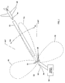
- Fig. 1 shows an aircraft landing system 20 located at a runway 22 for guiding an incoming aircraft 24 to a safe landing on the runway.
- system 20 is a microwave landing system (MLS).
- System 20 includes a phased array antenna 26 comprising a linear array of antenna elements 28 located beyond the end of the runway 22 and oriented perpendicular to the longitudinal dimension of the runway.
- Antenna 26 is centered on the longitudinal axis 30 of runway 22 for generating symmetrically two broad OCI beams 32 simultaneously and, at a later time, a single narrow guide beam 34 which is swept to and fro symmetrically about the axis 30.
- Antenna 26 is symmetric about an antenna centerline or axis which coincides with the runway axis 30.
- a data antenna 36 transmits a data signal and has a broad sector antenna pattern. Signals transmitted by the antennas 26 and 36 are generated by a ground-based signal source 38, and are received by an airborne receiver 40 carried by aircraft 24.
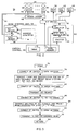
- Fig. 2 shows components of the signal source 38, and the interconnection of signal source 38 with the array antenna 26, the data antenna 36 and additional OCI antennas (not shown in Fig. 1) which may be present in the system 20 to provide additional OCI signals in designated time slots to compensate for anomalies in local geographic features.
- Two such additional OCI antennas 42 and 44 are shown in Fig. 2.
- Elements 28 of the array antenna 26 are connected via phase shifter elements, or phasors, 46 to a power divider 48.
- Electromagnetic power, to be radiated from the elements 28 of the antenna 26, is provided by a transmitter 50.
- the transmitter 50 is coupled via an RF (radio frequency) switch 52 to the power divider 48, and then via respective ones of the phasors 46 to individual ones of the elements 28.
- RF radio frequency
- Divider 48 divides the power of the transmitter 50 among the antenna elements 28.
- the division of power among the antenna elements 28 is selected so as to produce an amplitude taper to the radiating aperture of the antenna 26 wherein signals of the radiating elements 28 located in the center of the antenna 26 receive a larger amplitude than do signals radiating from elements 28 located away from the center of the antenna 26.
- the switch 52 also connects the transmitter 50 to the data antenna 36 and to the additional OCI antennas 42 and 44.
- the switch 52 allows power from the transmitter 50 to be coupled alternately among the antenna 26, 36, 42 and 44.
- a beam steering unit 54 which outputs phase shift command signals via a bus 56 to the phasors 46.
- the phasors 46 are responsive to the phase shift command signals to apply specific values of phase shift to electromagnetic signals radiated by the antenna elements 28 for forming, in accordance with the invention, either the pair of OCI beams 32 or the scanning guidance beam 34 from the same array antenna 26. Operation of the transmitter 50 and of the beam steering unit 54 is directed by a station control 58.
- the transmitter 50 comprises an RF amplifier 60, a data modulator 62, and an exciter 64.
- the exciter 64 provides an RF carrier signal which is coupled via the modulator 62 to the amplifier 60.
- the RF carrier signal is amplified by the amplifier 60 to a suitable level.
- the power level is sufficiently low, approximately 20 watts, to permit the use of PIN diodes in the construction of the switch 52. Thereby, the switch 52 can operate electronically under command of the station control 58.
- the modulator 62 is activated by the station control 58 to modulate the RF signal.
- the modulator 62 is deactiveated by the station control 58 during transmission of RF signals from the array antenna 26 and the OCI antennas 42 and 44.
- the beam steering unit 54 comprises two memories 66 and 68 which are addressed by an address generator 70.
- the OCI memory 66 stores phase shift command signals to be applied to the phasors 46 for generation of the pair of OCI beams 32.
- the scan memory 68 stores phase shift command signals to be applied to be phasors 46 for generation of successive positions of the guidance beam 34 during a scanning of the guidance beam.
- the station control 58 comprises a timing unit 72 and a data memory 74.
- the timing unit 72 provides timing signals for operating the address generator 70, the switch 52, the amplifier 60, the modulator 62 and the exciter 64.
- the memory 74 stores data signals to be applied to the modulator 62 for modulation of the RF carrier with the data.
- the station control 58 may be constructed as a computer which is preprogrammed to direct formation of the various beams and signal formats at the appropriate times for guiding an aircraft to a landing.
- the station control 58 transmits start, stop and timing signals to the beam steering unit 54.
- the memory 66 stores the phase-shift command signals in conjunction with identification numbers of the respective phasors 46.
- the generator 70 addresses the memory 66 to apply, via the bus 56, phase-shift comand signals to respective ones of the phasors 46. This establishes the requisite phase shifts to signals radiated by the respective antenna elements 28.
- the station control 58 also strobes the exciter 64 to produce pulses of the RF carrier to be applied via the phasors 46 to the antenna elements 28 for radiation from the antenna elements 28. Pulses of RF carrier are produced for generation of the OCI beams 32 and the scanned guidance beam 34.
- the generator 70 continues to address the memory 66 for updating the values of phase shift so as to scan the guidance beam 34 across the runway 22.
- Each of the phasors 46 includes a decoder (not shown) to enable the phasors 46 to respond to their respective command signals on the bus 56.
- each of the phasors 46 may comprise a counter with up/down and preset controls as is disclosed in United States patent 4,670,756 issued in the name of A. R. Lopez on June 2, 1987. The invention is not restricted to any specific form of phasor 46.
- the phased array antenna 26 develops the guidance beam 34 and sweeps the beam 34 to and fro about the airport runway 22 for guiding the aircrft 24 in azimuth.
- a sequence of signal transmissions from the various antennas is initiated with a data preamble transmitted by the data antenna 36.
- the data preamble includes a timing signal which synchronizes the aircraft MLS receiver 40 to the times of occurrence of the beams from the various antennas including the sweeping pattern of the swept beam 34.
- the array antenna 26 develops the two OCI sector beams 32 transversely to the runway 22 in regions of space outside the sweeping range of the guidance beam 34.
- the OCI beams provide reference signals to the airborne MLS receiver 40 to allow the MLS receiver 40 to determine that the aircraft 24 is within an out-of-coverage region.
- the foregoing antennas are arranged in a cluster centered on a runway axis and located beyond the far end of the runway, so as to transmit the swept beam down the runway towards an incoming aircraft.
- the preferred embodiment of the invention allows a sequence of up to six time slots for the generation of the OCI signals. The six time slots are followed by one cycle of the swept guidance beam which provides azimuth angle of the aircraft relative to the runway.
- the foregoing sequence of transmissions is provided in a repeating sequence so that the MLS receiver 40 can continually update the aircraft position.
- the sequence of operational steps begins at block 76 and proceeds to block 78 wherein the RF switch 52 is operated to connect the data antenna 36 to the transmitter 50. This is followed at block 80 with the transmission of the data preamble from the data antenna 36, the data preamble containing timing and identification for activating the airborne receiver 40. Also the beam steering unit 54 is preset for generation of the two OCI beams 32 from the array antenna 26. Thereafter, at block 84, switch 52 is operated to couple the transmitter 50 to the array antenna 26. This is followed, at block 84 with the transmission of the OCI signals in the two OCI beams 32 (Fig. 1) from the array antenna 26.
- the transmission of the OCI beams is accomplished by setting the phasors 46 with phase shifts provided by the OCI memory 66, and by activating the exciter 64 and the amplifier 60 to produce a pulse of RF carrier to be radiated by antenna 26.
- the operation continues at block 86 with the operation of the RF switch 52 to connect the tramsitter 50 to additional OCI antennas 42 and 44.
- the exciter 64 and the amplifier 60 are operated by the station control 58, at block 88, to produce the required pulses of RF carrier to be radiated by antennas 42 and 44.
- the beam steering unit 54 is preset to initiate the to-and-fro scan of the guidance beam 34 from the array antenna 26.
- the switch 52 Upon the conclusion of transmission of the remaining OCI pulses, the switch 52 is operated, at block 90, to connect trasmitter 50 back to the array antenna 26.
- the swept guidance beam 34 is then transmitted, at block 92, by activating the exciter 64 and the amplifier 60 to produce a pulse of RF carrier and, concurrently with the generation of this RF pulse, to apply phase shift commands from the beam steering unit 54 to the phasors 46.
- the phase shift commands are updated continuously to provide for the sweeping of the guidance beam 34.
- the operational sequence returns to block 78.
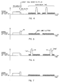
- Figs. 4 - 7 the signals received at the airborne MLS receiver 40 are depicted.
- the signals are transmitted in a sequence wherein the OCI signal provided by th array antenna 26 is transmitted during the first available OCI time slot.
- the aircraft 24 (Fig. 1) is located at an azimuth of +30°, and receives the signals sequentially as a function of time as shown in the graph of Fig. 4.
- First the preamble is received from the data antenna 36. This is followed by the OCI signal which is depicted at reduced amplitude because the aircraft is out of the strong signal region of the beams 32.
- the aircraft receives the signal of the guidance beam 34 during a "TO" sweep followed by a reception of the guidance beam signal during a "FRO" sweep. Also depicted in each of the graphs of Figs. 4 - 7, is low amplitude side-lobe clutter surrounding the beam 34 in the radiation pattern of the beam 34.
- Fig. 5 presents basically the same situation a Fig. 4, except that in the situation of Fig. 5, the aircraft is located at an azimuth of +70°, this being outside the sweeping range of the guidance beam 34 and close to the strong signal region of the OCI beams 32. Therefore, the signal of the OCI beams 32 is depicted with relatively large amplitude, while the main beam signal of the guidance beam 34 is omitted.
- Fig. 6 presents basically the same as Fig. 4, except that in the situation of Fig. 6, the aircraft is located at an azimuth of -30°, and receives the signals sequentially as a function of time as shown in the graph of Fig. 6.
- the preamble is received from the data antenna 36.
- the OCI signal which is depicted at reduced amplitude because the aircraft is out of the strong signal region of the beams 32.
- the aircraft is out of the strong signal of the guidance beam 34 during a "TO" sweep followed by a reception of the guidance beam signal during a "FRO" sweep.
- the "TO" signal is received earlier than in Fig. 4, and the "FRO" signal is received later than in Fig. 4 because of the differences in locations of the aircraft relative to the runway 22.
- Fig. 7 presents basically the same situation as Fig. 4, except that in the situation of Fig. 7, the aircraft is located at an azimuth of -70°, this being outside the sweeping range of the guidance beam 34 and close to the strong signal region of the OCI beams 32. Therefore, the signal of the OCI beams 32 is depicted with relatively large amplitude, while the main beam signal of the guidance beam 34 is omitted.
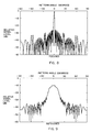
- Figs. 8 and 9 show, respectively, a focused and a defocused form of a beam produced by the antenna 26 and directed along the antenna axis 30.
- the focused beam of Fig. 8, which is much narrower than the defocused beam of Fig. 9, is employed as the guidance beam to be swept about the runway 30, as has been described above. Only the central position of the swept guidance beam is presented in Fig. 8.
- the radiation pattern of Fig. 9 demonstrates that the beam can become sufficiently broad by defocusing to be suitable as an OCI beam.
- Two such defocused beams are provided by the antenna 26 in accordance with the invention, as will now be described.
- the antenna 26 By deflecting the beam of Fig. 8 beyond the normal scan range, a grating lobe appears.
- the antenna 26 Upon defocusing both the main lobe and the grating lobe, as is depicted in Fig. 10, the antenna 26 provides two OCI beams disposed on opposite sides of the region of the swept main guidance beam. In this way, the invention provides for the generation of both the scanning beam and the OCI beams by use of a single phased array antenna, namely antenna 26.
- the invention feature of employing the single phased array antenna 26 for the generation of both the scanning beam and the two fixed OCI beams may be explained as follows.
- an incoming electromagnetic wave, incident upon the array of antenna elements 28 induces electric signals in the elements 28 which differ in phase by an amount proportional to the sine of an angle of inclination of the direction of propagation of the wave relative to a normal to the linear array of the elements 28.
- the spacing between grating lobes is equal to the ratio of wavelength divided by the interelement spacing between two successive antenna elements 28. This is the reciprocal of the interelement spacing expressed in wavelengths.
- Two lobes namely the main lobe and a grating lobe, each in a defocused condition, are shown in Fig. 10.
- the two lobes may be steered to the right or to the left by the introduction of additional phase shift at each of the phasors 46.
- the phase shift introduced by the phasors 46 is adjusted so that the grating lobe and the main lobe are symmetrically positioned about the array axis, as depicted in Fig. 10 for generation of the two OCI beams.
- the line array of elements 28 of the antenna 26 has fifty-two elements, there being twenty-six elements on one side of the antenna axis and twenty-six elements on the other side of the antenna axis.
- the electromagnetic wavelength is 5,926 cm (2.333 inches), and the distance between the antenna elements is 3,459 cm (1.362 inches) measured on centers of the elements 28. Therefore,
- the spacing between the lobes in Fig. 11 is 4,351 cm (1.7129 inches).
- the offset between either of the main and the grating lobes and the array axis is one-half the spacing between lobes.
- the offset may be expressed in radians by taking the inverse sine of the offset in sine 0 space. Expressed in degrees, the offset is 58.9°.
- the two beams portrayed in Fig. 10 are attained by scanning the main lobe off center to an angle of 58.92°, the defocusing broadens each beam to fill a sector ranging from 42° to 90° as measured from the antenna axis.
- the phasing of the array elements 28 is computed by assuming that a point source of radiation is located directly behind the center of the array aperture at a distance of 51.58 wavelengths.
- the phase gradiant provided by the phasors 46 is 180° per antenna element, this phase gradiant being added to a defocusing phase pattern to produce the individual amounts of phase shift between successive ones of the antenna elements 28.
- Defocusing of an antenna beam is well known, and is readily accomplished by introduction of a quadratic phase shift pattern among the antenna elements 28, this being in addition to the linear phase gradiant employed in the scanning of the beam to a desired angle off of the antenna axis.
- the defocusing phase component superimposed upon the linear phase gradient provides a beamwidth of 16.5° for the main beam, measured with the main beam directed at broadside.
- the resluting OCI dual-sector pattern has a gain relative to the peak scanning beam gain as follows. For an array antenna with a beamwidth of one degree, the OCI gain is -15dB with respect to the peak array gain. For an antenna array with a beamwidth of two degrees, the OCI gain is -12dB.
- Tables 1 and 2 provide information concerning construction of the invention, Table 1 and Table 2 providing the same information concerning respective ones of the antenna elements 28.
- the information provided for each element 28 includes its position in the radiating aperture of the antenna 26 as measured in wavelengths from one end element of the antenna 26, the relative amplitude of a signal radiated from the element 28 in decibels compared to a maximum radiated intensity of the center elements 28, and the phase angle in degrees applied by a phasor 46 to the element 28.
- Table 1 discloses this information for the first twenty-six phasors
- Table 2 discloses this information for the twenty-seventh through the fifty-second phasor.
Landscapes
- Engineering & Computer Science (AREA)
- Computer Networks & Wireless Communication (AREA)
- Physics & Mathematics (AREA)
- General Physics & Mathematics (AREA)
- Radar, Positioning & Navigation (AREA)
- Remote Sensing (AREA)
- Variable-Direction Aerials And Aerial Arrays (AREA)
- Traffic Control Systems (AREA)
Claims (5)
- Matériel d'antenne destiné à une utilisation au sol dans un système d'atterrissage pour avion ayant un matériel (40) aéroporté coopérant avec le matériel au sol;
le matériel au sol comprenant une antenne à réseau (26) et une antenne sectorielle (36);
un premier moyen (62) générateur de signaux ayant pour fonction de fournir un signal de données à l'antenne sectorielle (36), le signal de données contenant des informations utiles pour la synchronisation du matériel aéroporté avec le fonctionnement du matériel au sol;
un deuxième moyen (66) générateur de signaux ayant pour fonction de fournir un ensemble de signaux à l'antenne à réseau (26) pour produire un diagramme de rayonnement d'indication de sortie de couverture (ISC) ayant une paire de lobes (32) formant des angles sensiblement symétriques par rapport à l'axe du réseau;
un troisième moyen (68) générateur de signaux ayant pour fonction de fournir un ensemble de signaux à l'antenne à réseau (26) pour produire un faisceau qui balaye en aller-retour autour de l'axe du réseau; et
un moyen (58, 70) de commande pour commander le fonctionnement, le cadencement et la synchronisation des deuxième et troisième moyens (66, 68) générateurs de signaux, le moyen (58, 70) de commande comprenant un moyen de commutation pour coupler les deuxième ou troisième moyens (66, 68) générateurs de signaux à l'antenne à réseau (26) à des instants sélectionnés, et un moyen de cadencement (72) relié aux premier, deuxième et troisième moyens (62, 66, 68) générateurs de signaux pour synchroniser leurs fonctionnements;
caractérisé en ce que :
l'antenne à réseau (26) est une antenne à réseau phasé; et
le moyen de commande (58, 70) commande le deuxième moyen (66) générateur de signaux pour fournir l'ensemble de signaux afin que l'antenne à réseau (26) produise le diagramme de rayonnement d'lSC, l'un des lobes d'lSC (32) étant un lobe principal et l'autre des lobes d'lSC (32) étant un lobe de réseau, le lobe principal étant formé en tant que lobe principal du faisceau produit comme conséquence du fonctionnement du troisième moyen (68) générateur de signaux mais étant dirigé vers un côté de l'axe, et le lobe de réseau apparaissant ensuite de l'autre côté de l'axe axe comme résultat de cette orientation du lobe principal vers le côté. - Matériel d'antenne selon la revendication 1, caractérisé en ce que les lobes d'lSC sont constitués par les lobes principal et de réseau mais sont défocalisés par comparaison à l'état qu'ils présenteraient s'ils étaient produits comme conséquence du fonctionnement du troisième moyen générateur de signaux.
- Matériel d'antenne selon la revendication 1 ou la revendication 2, caractérisé en ce que l'antenne à réseau (26) comprend un réseau d'éléments (28) d'antenne, et en ce qu'un ensemble de déphaseurs (46) sont individuellement couplés entre les éléments d'antenne et les deuxième et troisième moyens générateurs de signaux.
- Matériel d'antenne selon la revendication 3, caractérisé en ce que le deuxième moyen (66) générateur de signaux comprend une mémoire (66) pour stocker des valeurs de déphasage associées au diagramme d'lSC souhaité.
- Matériel d'antenne selon la revendication 4, caractérisé en ce que les valeurs du déphasage du diagramme d'ISC sont appliquées à des signaux radiofréquence en chacun des éléments d'antenne (28) avec un gradient de phase de 180° par élément d'antenne plus un accroissement de phase de défocalisation.
Applications Claiming Priority (2)
| Application Number | Priority Date | Filing Date | Title |
|---|---|---|---|
| US07/377,874 US4968982A (en) | 1989-07-10 | 1989-07-10 | Aircraft landing system having simplified out-of-coverage indication (OCI) |
| US377874 | 1989-07-10 |
Publications (2)
| Publication Number | Publication Date |
|---|---|
| EP0408193A1 EP0408193A1 (fr) | 1991-01-16 |
| EP0408193B1 true EP0408193B1 (fr) | 1994-12-28 |
Family
ID=23490849
Family Applications (1)
| Application Number | Title | Priority Date | Filing Date |
|---|---|---|---|
| EP90306409A Expired - Lifetime EP0408193B1 (fr) | 1989-07-10 | 1990-06-12 | Système d'atterrissage pour avion ayant un indicateur de non-couverture simplifié |
Country Status (6)
| Country | Link |
|---|---|
| US (1) | US4968982A (fr) |
| EP (1) | EP0408193B1 (fr) |
| JP (1) | JPH0346581A (fr) |
| AU (1) | AU625829B2 (fr) |
| CA (1) | CA2019677A1 (fr) |
| DE (1) | DE69015477D1 (fr) |
Families Citing this family (5)
| Publication number | Priority date | Publication date | Assignee | Title |
|---|---|---|---|---|
| JP2950296B2 (ja) * | 1997-07-15 | 1999-09-20 | 日本電気株式会社 | 航空機の所定空間通過検出装置 |
| FR2946022B1 (fr) * | 2009-05-26 | 2013-02-08 | Airbus France | Systeme de protection de zones dangereuses. |
| US9069077B2 (en) * | 2013-01-11 | 2015-06-30 | Garmin Switzerland Gmbh | Traffic information services-broadcast (TIS-B) traffic snooping |
| WO2019101837A1 (fr) * | 2017-11-24 | 2019-05-31 | Sony Corporation | Informations de système pour sélection/resélection de cellule par un ue aérien |
| CN111047222B (zh) * | 2019-12-30 | 2023-04-28 | 四川函钛科技有限公司 | 一种基于时序qar参数的接地时间点判定方法 |
Family Cites Families (6)
| Publication number | Priority date | Publication date | Assignee | Title |
|---|---|---|---|---|
| US4178581A (en) * | 1978-11-03 | 1979-12-11 | The Bendix Corporation | Integrated antenna aperture |
| GB2034525B (en) * | 1978-11-17 | 1983-03-09 | Marconi Co Ltd | Microwave transmission systems |
| GB2055000B (en) * | 1979-07-06 | 1983-09-28 | Plessey Co Ltd | Microwave landing systems |
| US4677442A (en) * | 1984-05-29 | 1987-06-30 | Hazeltine Corporation | Microwave landing system with ±90 degree azimuth clearance guidance and 360 degree data coverage |
| US4635064A (en) * | 1985-04-04 | 1987-01-06 | Sundstrand Data Control, Inc. | Microwave landing system |
| US4837580A (en) * | 1987-05-14 | 1989-06-06 | Hazeltine Corporation | Microwave landing system with fail-soft switching of dual transmitters, beam steering and sector antennas |
-
1989
- 1989-07-10 US US07/377,874 patent/US4968982A/en not_active Expired - Fee Related
-
1990
- 1990-06-12 EP EP90306409A patent/EP0408193B1/fr not_active Expired - Lifetime
- 1990-06-12 DE DE69015477T patent/DE69015477D1/de not_active Expired - Lifetime
- 1990-06-21 AU AU57704/90A patent/AU625829B2/en not_active Ceased
- 1990-06-22 CA CA002019677A patent/CA2019677A1/fr not_active Abandoned
- 1990-07-09 JP JP2181364A patent/JPH0346581A/ja active Pending
Also Published As
| Publication number | Publication date |
|---|---|
| CA2019677A1 (fr) | 1991-01-10 |
| DE69015477D1 (de) | 1995-02-09 |
| EP0408193A1 (fr) | 1991-01-16 |
| AU5770490A (en) | 1991-01-10 |
| US4968982A (en) | 1990-11-06 |
| JPH0346581A (ja) | 1991-02-27 |
| AU625829B2 (en) | 1992-07-16 |
Similar Documents
| Publication | Publication Date | Title |
|---|---|---|
| US5442364A (en) | Alignment and beam spreading for ground radial airborne radar | |
| CA1128198A (fr) | Ouverture effective d'antenne integree | |
| US3448450A (en) | Pulse radar for determining angles of elevation | |
| US4408205A (en) | Multiple beam antenna feed arrangement for generating an arbitrary number of independent steerable nulls | |
| CN103339797B (zh) | 在毫米和亚毫米波段实现组合的雷达和辐射成像的成像系统和方法 | |
| US4562439A (en) | Imaging radar seeker | |
| RU2146379C1 (ru) | Вторичная обзорная радиолокационная станция | |
| EP3631504B1 (fr) | Appareil et procédés d'imagerie radar à synthèse d'ouverture | |
| US5896105A (en) | Distributed phased array antenna system | |
| JPS62108175A (ja) | レ−ダ装置 | |
| US3017630A (en) | Radar scanning system | |
| EP0408193B1 (fr) | Système d'atterrissage pour avion ayant un indicateur de non-couverture simplifié | |
| US3349399A (en) | Beacon system for simultaneous azimuth and elevation determination | |
| JPS6243144B2 (fr) | ||
| GB2356096A (en) | Radar antenna system | |
| US3878523A (en) | Generation of scanning radio beams | |
| US2682048A (en) | Radio object detection apparatus | |
| JPH09178846A (ja) | 衛星搭載合成開口レーダ | |
| US4053892A (en) | System for enabling coherent signal processing at a remote receiving station | |
| US3971026A (en) | Multiple beam glide slope radio navigation method with two classes of beams | |
| US5132690A (en) | Low power polystatic radar method and system | |
| US3815134A (en) | Ground clutter reduction apparatus | |
| US4912479A (en) | Microwave landing system | |
| US7280072B2 (en) | System for the relative navigation of aircraft and spacecraft using a phased array antenna | |
| US4764772A (en) | Scanning-beam microwave landing system |
Legal Events
| Date | Code | Title | Description |
|---|---|---|---|
| PUAI | Public reference made under article 153(3) epc to a published international application that has entered the european phase |
Free format text: ORIGINAL CODE: 0009012 |
|
| AK | Designated contracting states |
Kind code of ref document: A1 Designated state(s): DE FR GB IT NL |
|
| 17P | Request for examination filed |
Effective date: 19910626 |
|
| 17Q | First examination report despatched |
Effective date: 19930709 |
|
| GRAA | (expected) grant |
Free format text: ORIGINAL CODE: 0009210 |
|
| AK | Designated contracting states |
Kind code of ref document: B1 Designated state(s): DE FR GB IT NL |
|
| PG25 | Lapsed in a contracting state [announced via postgrant information from national office to epo] |
Ref country code: NL Effective date: 19941228 |
|
| ITF | It: translation for a ep patent filed | ||
| REF | Corresponds to: |
Ref document number: 69015477 Country of ref document: DE Date of ref document: 19950209 |
|
| ET | Fr: translation filed | ||
| PG25 | Lapsed in a contracting state [announced via postgrant information from national office to epo] |
Ref country code: DE Effective date: 19950329 |
|
| PG25 | Lapsed in a contracting state [announced via postgrant information from national office to epo] |
Ref country code: GB Effective date: 19950612 |
|
| NLV1 | Nl: lapsed or annulled due to failure to fulfill the requirements of art. 29p and 29m of the patents act | ||
| PLBE | No opposition filed within time limit |
Free format text: ORIGINAL CODE: 0009261 |
|
| STAA | Information on the status of an ep patent application or granted ep patent |
Free format text: STATUS: NO OPPOSITION FILED WITHIN TIME LIMIT |
|
| 26N | No opposition filed | ||
| GBPC | Gb: european patent ceased through non-payment of renewal fee |
Effective date: 19950612 |
|
| PG25 | Lapsed in a contracting state [announced via postgrant information from national office to epo] |
Ref country code: FR Effective date: 19960229 |
|
| REG | Reference to a national code |
Ref country code: FR Ref legal event code: ST |
|
| PG25 | Lapsed in a contracting state [announced via postgrant information from national office to epo] |
Ref country code: IT Free format text: LAPSE BECAUSE OF NON-PAYMENT OF DUE FEES;WARNING: LAPSES OF ITALIAN PATENTS WITH EFFECTIVE DATE BEFORE 2007 MAY HAVE OCCURRED AT ANY TIME BEFORE 2007. THE CORRECT EFFECTIVE DATE MAY BE DIFFERENT FROM THE ONE RECORDED. Effective date: 20050612 |