EP0408583B1 - Behälter und verabreichungssystem für flüssige chemikalien - Google Patents
Behälter und verabreichungssystem für flüssige chemikalien Download PDFInfo
- Publication number
- EP0408583B1 EP0408583B1 EP89902903A EP89902903A EP0408583B1 EP 0408583 B1 EP0408583 B1 EP 0408583B1 EP 89902903 A EP89902903 A EP 89902903A EP 89902903 A EP89902903 A EP 89902903A EP 0408583 B1 EP0408583 B1 EP 0408583B1
- Authority
- EP
- European Patent Office
- Prior art keywords
- pouch
- bottle
- liquid
- container
- fitment
- Prior art date
- Legal status (The legal status is an assumption and is not a legal conclusion. Google has not performed a legal analysis and makes no representation as to the accuracy of the status listed.)
- Expired - Lifetime
Links
- 239000007788 liquid Substances 0.000 title claims abstract description 62
- 239000000126 substance Substances 0.000 title claims abstract description 43
- 239000000523 sample Substances 0.000 claims abstract description 21
- 239000012530 fluid Substances 0.000 claims description 10
- 239000012528 membrane Substances 0.000 claims description 10
- 238000011109 contamination Methods 0.000 claims description 8
- 238000007789 sealing Methods 0.000 claims description 4
- 238000003860 storage Methods 0.000 abstract description 5
- 230000005484 gravity Effects 0.000 abstract description 2
- 239000010409 thin film Substances 0.000 abstract 1
- 239000004811 fluoropolymer Substances 0.000 description 14
- 229920002313 fluoropolymer Polymers 0.000 description 14
- -1 photo-resists Substances 0.000 description 12
- 239000000463 material Substances 0.000 description 9
- 239000004698 Polyethylene Substances 0.000 description 8
- 239000004033 plastic Substances 0.000 description 8
- 229920003023 plastic Polymers 0.000 description 8
- 229920000573 polyethylene Polymers 0.000 description 8
- 230000008878 coupling Effects 0.000 description 6
- 238000010168 coupling process Methods 0.000 description 6
- 238000005859 coupling reaction Methods 0.000 description 6
- 230000007246 mechanism Effects 0.000 description 6
- 239000002184 metal Substances 0.000 description 6
- 239000011521 glass Substances 0.000 description 5
- 238000000034 method Methods 0.000 description 5
- IJGRMHOSHXDMSA-UHFFFAOYSA-N Atomic nitrogen Chemical compound N#N IJGRMHOSHXDMSA-UHFFFAOYSA-N 0.000 description 4
- 230000008901 benefit Effects 0.000 description 3
- 239000004743 Polypropylene Substances 0.000 description 2
- 239000011888 foil Substances 0.000 description 2
- 238000004519 manufacturing process Methods 0.000 description 2
- 229910021645 metal ion Inorganic materials 0.000 description 2
- 229910052757 nitrogen Inorganic materials 0.000 description 2
- 239000002245 particle Substances 0.000 description 2
- 229920001155 polypropylene Polymers 0.000 description 2
- 238000013022 venting Methods 0.000 description 2
- 229920002799 BoPET Polymers 0.000 description 1
- 239000005041 Mylar™ Substances 0.000 description 1
- 239000004677 Nylon Substances 0.000 description 1
- 239000002253 acid Substances 0.000 description 1
- 150000007513 acids Chemical class 0.000 description 1
- 239000000853 adhesive Substances 0.000 description 1
- 230000001070 adhesive effect Effects 0.000 description 1
- 239000005391 art glass Substances 0.000 description 1
- 239000002585 base Substances 0.000 description 1
- 230000008859 change Effects 0.000 description 1
- 238000004140 cleaning Methods 0.000 description 1
- 238000010276 construction Methods 0.000 description 1
- 230000006378 damage Effects 0.000 description 1
- 230000000994 depressogenic effect Effects 0.000 description 1
- 238000013461 design Methods 0.000 description 1
- 238000010586 diagram Methods 0.000 description 1
- 238000006073 displacement reaction Methods 0.000 description 1
- 239000002019 doping agent Substances 0.000 description 1
- 239000003814 drug Substances 0.000 description 1
- 239000012632 extractable Substances 0.000 description 1
- 239000007789 gas Substances 0.000 description 1
- 231100001261 hazardous Toxicity 0.000 description 1
- 238000012423 maintenance Methods 0.000 description 1
- 230000013011 mating Effects 0.000 description 1
- 239000002991 molded plastic Substances 0.000 description 1
- 229920001778 nylon Polymers 0.000 description 1
- 238000004806 packaging method and process Methods 0.000 description 1
- 229920002120 photoresistant polymer Polymers 0.000 description 1
- 229920002223 polystyrene Polymers 0.000 description 1
- 229920001343 polytetrafluoroethylene Polymers 0.000 description 1
- 239000004810 polytetrafluoroethylene Substances 0.000 description 1
- 239000004800 polyvinyl chloride Substances 0.000 description 1
- 229920000915 polyvinyl chloride Polymers 0.000 description 1
- 238000002360 preparation method Methods 0.000 description 1
- 230000008569 process Effects 0.000 description 1
- 238000012545 processing Methods 0.000 description 1
- 230000002285 radioactive effect Effects 0.000 description 1
- 230000001105 regulatory effect Effects 0.000 description 1
- 239000002904 solvent Substances 0.000 description 1
- 238000012360 testing method Methods 0.000 description 1
Images








Classifications
-
- B—PERFORMING OPERATIONS; TRANSPORTING
- B67—OPENING, CLOSING OR CLEANING BOTTLES, JARS OR SIMILAR CONTAINERS; LIQUID HANDLING
- B67D—DISPENSING, DELIVERING OR TRANSFERRING LIQUIDS, NOT OTHERWISE PROVIDED FOR
- B67D7/00—Apparatus or devices for transferring liquids from bulk storage containers or reservoirs into vehicles or into portable containers, e.g. for retail sale purposes
- B67D7/02—Apparatus or devices for transferring liquids from bulk storage containers or reservoirs into vehicles or into portable containers, e.g. for retail sale purposes for transferring liquids other than fuel or lubricants
- B67D7/0238—Apparatus or devices for transferring liquids from bulk storage containers or reservoirs into vehicles or into portable containers, e.g. for retail sale purposes for transferring liquids other than fuel or lubricants utilising compressed air or other gas acting directly or indirectly on liquids in storage containers
- B67D7/0255—Apparatus or devices for transferring liquids from bulk storage containers or reservoirs into vehicles or into portable containers, e.g. for retail sale purposes for transferring liquids other than fuel or lubricants utilising compressed air or other gas acting directly or indirectly on liquids in storage containers squeezing collapsible or flexible storage containers
-
- B—PERFORMING OPERATIONS; TRANSPORTING
- B65—CONVEYING; PACKING; STORING; HANDLING THIN OR FILAMENTARY MATERIAL
- B65D—CONTAINERS FOR STORAGE OR TRANSPORT OF ARTICLES OR MATERIALS, e.g. BAGS, BARRELS, BOTTLES, BOXES, CANS, CARTONS, CRATES, DRUMS, JARS, TANKS, HOPPERS, FORWARDING CONTAINERS; ACCESSORIES, CLOSURES, OR FITTINGS THEREFOR; PACKAGING ELEMENTS; PACKAGES
- B65D47/00—Closures with filling and discharging, or with discharging, devices
- B65D47/36—Closures with frangible parts adapted to be pierced, torn or removed, to provide discharge openings
-
- B—PERFORMING OPERATIONS; TRANSPORTING
- B65—CONVEYING; PACKING; STORING; HANDLING THIN OR FILAMENTARY MATERIAL
- B65D—CONTAINERS FOR STORAGE OR TRANSPORT OF ARTICLES OR MATERIALS, e.g. BAGS, BARRELS, BOTTLES, BOXES, CANS, CARTONS, CRATES, DRUMS, JARS, TANKS, HOPPERS, FORWARDING CONTAINERS; ACCESSORIES, CLOSURES, OR FITTINGS THEREFOR; PACKAGING ELEMENTS; PACKAGES
- B65D51/00—Closures not otherwise provided for
- B65D51/18—Arrangements of closures with protective outer cap-like covers or of two or more co-operating closures
- B65D51/20—Caps, lids, or covers co-operating with an inner closure arranged to be opened by piercing, cutting, or tearing
-
- B—PERFORMING OPERATIONS; TRANSPORTING
- B65—CONVEYING; PACKING; STORING; HANDLING THIN OR FILAMENTARY MATERIAL
- B65D—CONTAINERS FOR STORAGE OR TRANSPORT OF ARTICLES OR MATERIALS, e.g. BAGS, BARRELS, BOTTLES, BOXES, CANS, CARTONS, CRATES, DRUMS, JARS, TANKS, HOPPERS, FORWARDING CONTAINERS; ACCESSORIES, CLOSURES, OR FITTINGS THEREFOR; PACKAGING ELEMENTS; PACKAGES
- B65D77/00—Packages formed by enclosing articles or materials in preformed containers, e.g. boxes, cartons, sacks or bags
- B65D77/04—Articles or materials enclosed in two or more containers disposed one within another
- B65D77/06—Liquids or semi-liquids or other materials or articles enclosed in flexible containers disposed within rigid containers
-
- B—PERFORMING OPERATIONS; TRANSPORTING
- B65—CONVEYING; PACKING; STORING; HANDLING THIN OR FILAMENTARY MATERIAL
- B65D—CONTAINERS FOR STORAGE OR TRANSPORT OF ARTICLES OR MATERIALS, e.g. BAGS, BARRELS, BOTTLES, BOXES, CANS, CARTONS, CRATES, DRUMS, JARS, TANKS, HOPPERS, FORWARDING CONTAINERS; ACCESSORIES, CLOSURES, OR FITTINGS THEREFOR; PACKAGING ELEMENTS; PACKAGES
- B65D2231/00—Means for facilitating the complete expelling of the contents
- B65D2231/02—Precut holes or weakened zones
-
- B—PERFORMING OPERATIONS; TRANSPORTING
- B65—CONVEYING; PACKING; STORING; HANDLING THIN OR FILAMENTARY MATERIAL
- B65D—CONTAINERS FOR STORAGE OR TRANSPORT OF ARTICLES OR MATERIALS, e.g. BAGS, BARRELS, BOTTLES, BOXES, CANS, CARTONS, CRATES, DRUMS, JARS, TANKS, HOPPERS, FORWARDING CONTAINERS; ACCESSORIES, CLOSURES, OR FITTINGS THEREFOR; PACKAGING ELEMENTS; PACKAGES
- B65D2231/00—Means for facilitating the complete expelling of the contents
- B65D2231/02—Precut holes or weakened zones
- B65D2231/022—Precut holes or weakened zones for permitting the insertion of a tubular contents-removing device, e.g. a drinking straw
-
- B—PERFORMING OPERATIONS; TRANSPORTING
- B65—CONVEYING; PACKING; STORING; HANDLING THIN OR FILAMENTARY MATERIAL
- B65D—CONTAINERS FOR STORAGE OR TRANSPORT OF ARTICLES OR MATERIALS, e.g. BAGS, BARRELS, BOTTLES, BOXES, CANS, CARTONS, CRATES, DRUMS, JARS, TANKS, HOPPERS, FORWARDING CONTAINERS; ACCESSORIES, CLOSURES, OR FITTINGS THEREFOR; PACKAGING ELEMENTS; PACKAGES
- B65D2251/00—Details relating to container closures
- B65D2251/0003—Two or more closures
- B65D2251/0006—Upper closure
- B65D2251/0025—Upper closure of the 47-type
-
- B—PERFORMING OPERATIONS; TRANSPORTING
- B65—CONVEYING; PACKING; STORING; HANDLING THIN OR FILAMENTARY MATERIAL
- B65D—CONTAINERS FOR STORAGE OR TRANSPORT OF ARTICLES OR MATERIALS, e.g. BAGS, BARRELS, BOTTLES, BOXES, CANS, CARTONS, CRATES, DRUMS, JARS, TANKS, HOPPERS, FORWARDING CONTAINERS; ACCESSORIES, CLOSURES, OR FITTINGS THEREFOR; PACKAGING ELEMENTS; PACKAGES
- B65D2251/00—Details relating to container closures
- B65D2251/0003—Two or more closures
- B65D2251/0068—Lower closure
- B65D2251/0093—Membrane
Definitions
- the invention relates to containers for storage, transport and use of liquid chemicals including acids, solvents, bases, photo-resists, dopants, inorganics, organics, biological solutions, pharmaceuticals, and radioactive chemicals.
- the invention relates to a container which uses a disposable film pouch within a bottle or overpack, and to dispensing systems used in conjunction with this container.
- a second, most widely-used alternative is to handle the liquid chemicals in bottles made of glass or polyethylene.
- This alternative has several disadvantages.
- glass and polyethylene have been shown to contribute both particulate contamination and metal-ion extractables which significantly compromise the level of desired purity of liquid chemicals.
- the dispensing methods used with glass and polyethylene bottles also compromise the purity of the chemical contents. Manual decanting exposes chemicals to atmospheric contamination, and also can compromise the safety of the technicians handling the bottles. With glass bottles, there is also the danger of breakage; even slight abuse to the bottles can be very hazardous if breakage occurs.
- Disposal of empty bottles is also a major concern. Disposal typically requires triple rinsing, tagging, and crushing before sanitary disposal. This process is labour intensive and tedious.
- a third alternative is the use of blow-molded fluoropolymer bottles.
- the manual handling of the bottle is maintained, yet the fluoropolymer bottle provides inertness which is critical to maintaining the purity of the chemicals being handled.
- These blow-molded bottles are very expensive and therefore have only been cost justified by the use of a returnable program in which the bottles are returned to the manufacturer for processing and reuse.
- a returnable program presents numerous logistical problems for suppliers and users alike.
- a fourth alternative is the use of containers provided with inner linings made of plastic material such as polyethylene, polyvinylchloride, polystyrol, or similar products.
- plastic material such as polyethylene, polyvinylchloride, polystyrol, or similar products.
- U Kingdom Patent GB-A-762567 in which the plastic lining is integral with a plastic bush which is screwed into a metal bush of the container. The container is closed with a plastic cap which is screwed to the plastic bush.
- a flexible bag has a rigid mouthpiece which is a snaplock fit in the mouth of a bottle. The base of the bag is adhered to the base of the bottle. Although the mouthpiece is formed with flexible flaps below its opening these do not form a seal and liquid is dispensed through the flaps.
- known containers employing this alternative have only one seal to prevent atmospheric contamination of the contents during shipping and storage. As a result, if the cap becomes loosened or is removed, the contents of the container may become atmospherically contaminated.
- a liquid chemical handling system comprising a container comprising: a flexible film pouch having an interior for holding liquid; a fitment sealed to the pouch and defining a port which communicates with the interior of the pouch; a bottle having a mouth which communicates with an interior of the bottle; and a cap which engages the mouth of the bottle and is positioned over the mouth of the bottle and the fitment; characterised by the provision of: seal means for sealing the port to seal against atmosphere contamination of liquid after the pouch has been filled with liquid through the port; and retaining means for engaging the neck of the fitment and the interior of the mouth of the bottle, which retaining means has a vent passage for permitting air to enter the interior of the bottle around the pouch as liquid is dispensed from the pouch;
- the container is capped with a cap which includes a break seal for closing the opening of the fitment.
- a dispensing closure is attached to the cap of the container and includes a probe which breaks the seal provided by the cap.
- the dispensing closure includes a valve which is normally closed to prevent flow of the liquid until the dispensing closure has been inserted into a dispensing receptacle. The engagement of the dispensing closure and the receptacle opens the valve, and allows flow of the liquid chemical out of the pouch, through the valve, and through an outlet to a metering or other liquid flow control device.
- automated dispensing of the contents of the pouch are provided by a system which includes a pressure vessel into which the container is placed. Vent openings allow air to enter the region between the inner wall of the bottle and the pouch.
- the interior of the pressure vessel is pressurized, so that there is no pressure differential between the inside and outside of the bottle, but there is pressure being applied to the pouch which causes it to collapse as liquid is forced out of the pouch through the fitment and through a valve probe which has been inserted in the mouth of the fitment.
- Figure 1 is a perspective view of a preferred embodiment of the container of the present invention.
- Figure 2 is a perspective view, similar to Figure 1, with the cap of the container removed.
- Figure 3 is a sectional view along section 3-3 of Figure 1.
- Figures 4A and 4B are top and side elevational views of the pouch and fitment of the container of Figure 1-3.
- Figures 5A and 5B are perspective views of the retainer of container of Figures 1-3.
- Figure 6 is a top view of the cap of the container of Figure 1.
- Figure 7 is a top view of an alternative embodiment of the cap.
- Figures 8A and 8B are sectional views, generally along section 8-8 of Figure 7, showing the cap during shipping and during opening of a vent hole and removal of a tear-away seal, respectively.
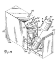
- Figure 9 is a perspective diagram illustrating a manual dispensing system used with the container of Figure 1.
- Figure 10 is an exploded sectional view of the manual dispensing system of Figure 9.
- Figure 11 is a sectional view of the manual dispensing system of Figure 9 showing the system in operation.
- Figure 12 is a sectional view of another embodiment of a manual dispensing system which includes a metering pump.
- Figure 13 is a perspective view of an automated dispensing system used with the container of the present invention.
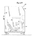
- Figure 14A and 14B are side views showing a pressure vessel and drawer of the system of Figure 13 in two different positions.
- Figure 14C is a front view of the system of Figure 13.
- Figures 15A, 15B and 15C are side views showing the vessel cover in three different positions.
- Figures 16A and 16B are top and rear views of the pressure vessel.
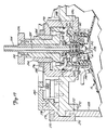
- Figure 17 is a sectional view along section 17-17 of Figure 16A showing the dispensing valve mechanism of the automated system of Figure 13.
- Figures 1-6 illustrate a preferred embodiment of container 10, which includes five main components: inner pouch 12, fitment 14, outer bottle 16, retainer 18, and cap 20.
- Pouch 12 which is best shown in Figures 3, 4A and 4B, is preferably constructed of a fluoropolymer film, such as polytetrafluoroethylene, in a one to twenty mil thickness range.
- a film sheet 21 is folded to form two identical opposing film sheets 21A and 21B.
- Heat seals 23A-23C around the outer edges of sheets 21A and 21B form pouch 12.
- additional film laminants such as nylon, mylar, or metal foil may be added to the layer of fluoropolymer film.
- a reflective metal foil may be used on an outer surface of pouch 12 when the liquid chemical to be stored within pouch 12 is a photoresist or other photosensitive liquid.
- the heat sealed shape of pouch 12 is contoured to minimize stress at joints.
- the capacity of pouch 12 is preferably slightly larger than that of bottle (or overpack) 16.
- fitment 14 Access to the interior of pouch 12 for filling and dispensing is gained through fitment 14, which extends through hole 25 in the top of sheet 21.
- Pouch 12 and fitment 14 are constructed of similar materials to allow for heat seal assembly.
- fitment 14 includes a mouth 22 with a lip 24 at its upper end, an intermediate neck 26, and a lower shoulder or flange 28.
- Flange 28 is heat sealed by seal 29 to the upper edge of pouch 12 surrounding hole 25.
- Outer bottle or overpack 16 provides the mechanical support and protection required by pouch 12 during filling, transport, handling, and dispensing.
- Bottle 16 is typically constructed of a plastic material such as polyethylene, although other materials including metal may also be used depending upon government regulatory specifications for handling of the particular liquid chemicals to be contained within container 10.
- Outer bottle 16 is a generally cylindrical closed vessel having a bottom 30, sidewalls 32, sloped top 34, externally threaded wide mouth 36, and integral handle 38.
- the sloped walls of top 34 are desirable because container 10 typically will be used in a manual or automated dispensing system in an inverted position.
- the sloped walls of top 34 ensure that fitment 14 is at the lower-most position when container 10 is inverted.
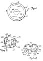
- Retainer 18 which is best shown in Figures 5A and 5B, is a clam shell type ring containing a pair of semi-circular segments 40A and 40B which are joined by living hinge 42.
- Each segment 40A, 40B includes generally horizontal portion 44A, 44B and upwardly projecting section 46A, 46B with upper flanges 48A, 48B, and downwardly projecting walls 50A, 50B.
- the intersection of walls 50A, 50B with horizontal sections 44A, 44B define a pair of flanges 52A, 52B.
- vent holes 54A, 54B are vent holes 54A, 54B.
- retainer 18 is placed around fitment 14 so that the top edges of upwardly projecting sections 46A and 46B engage the lower surface of flange 24 of fitment 14.
- Retainer 18 is placed within mouth 36 of bottle 16 so that walls 50A-50B are adjacent the inner walls of mouth 36 and flanges 52A-52B engage annular shoulder 56 near the top inner surface of mouth 36.
- Flanges 48A, 48B provide a gripping surface by which retainer 18 can be pulled out of mouth 36 after pouch 12 is empty and after cap 20 has been removed.
- Mouth 22 of fitment 14 is closed by break seal membrane 60, which is preferably a fluoropolymer film material.
- Membrane 60 is preferably scored to promote puncture when accessed by a proper dispensing connector (as will be described in more detail later.)
- Cap 20 is preferably constructed of a plastic material such as polypropylene, and has internal threads for engaging the external threads of mouth 36 of bottle 16. Cap 20 is designed to be screwed down onto bottle 16 to a predetermined torque to ensure a liquid and air-tight seal between fitment 14 and membrane 60 and between cap 20 and bottle 16.
- Cap 20 also includes a tear-away outer seal, which in the embodiment shown in Figures 1, 3, and 6 is an adhesive backed film 62 with a pull tab 64.
- Film 62 covers central main port 66 of cap 20, as well as vent port 68. Film 62 remains in place, providing a back up seal for container 10, until the contents of container 10 are to be dispensed. At that time, film 62 is torn away by grasping and pulling up on pull tab 64. This exposes main port 66 and vent port 68, but membrane 60 is still in place to provide a seal until an appropriate dispensing device is attached to cap 20.
- Vent port 68 and vent holes 54A and 54B provide a path for air to enter the interior of container 10 between pouch 12 and the walls of bottle 16. This permits air pressure to assist in collapsing bag 12 as liquid is dispensed.
- cap 20 includes coding keys or slots 70 in flange 71 which uniquely designate the particular liquid chemical contained within pouch 12. These slots 70 mate with the particular dispensing system to ensure that only the proper containers will be connected to the dispensing system.
- FIGs 7, 8A and 8B illustrate an alternative embodiment of the cap for use in the container of the present invention.
- Cap 80 shown in Figures 7, 8A and 8B is a molded plastic cap, preferably of polypropylene which contains an integral tear away portion 82 and tear away tab 84.
- Knock out 86 is positioned generally below tab 84, and covers vent port 88.
- Cap 80 has four upwardly projecting alignment pins 90 which are used for proper alignment of a dispensing mechanism over cap 80, and which also protect against accidental opening in the event bottle 16 and cap 80 are dropped. Also included are key coded slots 92 in flange 93, which identify the particular liquid chemical contained within the container, and thus prevent the container from being connected to the wrong dispensing system. Shallower slots 93 are circumferentially positioned in flange 93 for gripping and for allowing air to pass when a dispensing device is placed over cap 80.
- vent port 88 To open the vent port 88, tab 84 is pushed downward so that ramp 95 engages knock out 86 and breaks the connection at one edge between knock out 86 and the remainder of cap 80 so that vent port 88 is open. The main passage is then removed by pulling up on tab 84 to break the connections between section 82 and the remainder of cap 80.
- Container 10 of the present invention has significant advantages over the prior art containers for liquid chemicals.
- the portions of container 10 which contact the liquid chemicals i.e. pouch 12 and fitment 14
- outer bottle 16 which preferably is made of a plastic or metal, provides a construction which is more rugged than prior art glass containers.
- container 10 is less permeable than polyethylene containers.
- the overall cost of the container 10 is less than an all fluoropolymer blow-molded container, while still offering the advantages of fluoropolymer materials.
- pouch 12 is preferably evacuated prior to filling, which allows for a sealed connection during filling. This eliminates venting of displaced air, which benefits the maintenance of chemical purity of the liquid chemicals being delivered to the pouch.
- pouch 12 can be filled with nitrogen immediately upon manufacture and leak testing, and the nitrogen can be maintained in pouch 12 until filling with the liquid chemicals.
- container 10 with cap 20 provides two seals, including break seal or membrane 60 which is penetrated only when properly used in conjunction with a dispensing valve.
- cap 20 also seals to bottle 16. This ensures against atmospheric contamination of the contents during shipping and storage.
- the liquid chemical is actually "double contained,” i.e. within both pouch 12 and bottle 16, which adds to safety in handling and shipping.
- container 10 of the present invention dispensing can be accomplished using several different techniques.
- the container can simply be uncapped by removing cap 20 (or cap 80) and then manually inverted for decanting.
- cap 20 (or 80) can be removed and a tube inserted through fitment 14 into pouch 12, and the contents can be drawn out by use of a pump.
- FIG. 9-12 Still another technique for dispensing the contents of container 10 uses a manual dispensing valve assembly to which container 10 is connected.
- This manual system which is illustrated in Figures 9-12 includes a valve assembly which is connected to the container, and a platform which supports the container in an inverted position for gravity-assisted dispensing.
- Container 10 can also be advantageously used with an automated system like the one shown in Figures 13-17, in which container 10 is placed in a pressure vessel and a pressurized gas is applied to the exterior of pouch 12 to squeeze the contents out of pouch 12 through a mating connection and dispensing line.
- Figures 9-11 illustrate one preferred embodiment of a manual dispensing system 100 which includes male dispensing closure 102, female receptacle 104, and base 106.
- Male dispensing closure 102 is first fitted over cap 20 while container 10 is in an upright position, and the combination of container 10 and dispensing closure 102 are then inverted (as shown in Figure 9) and inserted into female receptacle 104 (as shown in Figure 11).
- dispensing closure 102 includes probe 110, check valve body 112, check valve housing 113, lock ring 114, key code cover 116, locking tabs 118, key tabs 120, bolts 122, check valve plunger 124, spring 126, and O-rings 128, 130, and 132.
- Key tabs 120 which are carried at the outer end of key code cover 116, mate with key code slots 70 of cover 20 to ensure that dispensing system 100 is the proper system for use with container 10. Once outer flange 71 of cover 20 has cleared key tabs 120, it passes four circumferentially spaced locking tabs 118, and is seated against key code cover 116. Lock ring 114 is rotatable to move the locking tabs 118 so that, once flange 71 is past locking tabs 118, it cannot be removed.
- probe 110 breaks membrane 60.
- O-ring 128 provides a seal between the inner wall of neck 26 of fitment 14 and the outer wall of probe 110.
- Probe 110 has a central bore 136 which is connected at one end to inlet passage 138 and at its opposite end to the interior of check valve body 112.
- a fluid flow passage is established from the interior of pouch 12 through passage 138 and bore 136 to the interior of check valve 112.
- Check valve body 124 is normally seated against check valve body 112, and O-ring 132 seals the outlet of check valve body 112 so that no liquid is dispensed even when dispensing closure 102 is inserted over cap 20 and container 10 is inverted.
- Female receptacle 104 is attached to top plate 140 of base 106 by screws 142.
- Base 106 also includes standoffs 144 to provide clearance beneath plate 140 for outlet tubing 146 and fitting 148.
- Manifold 150 Mounted within female receptacle 104 is manifold 150.
- Manifold 150 contains a cavity 152 for receiving check valve body 112. At the bottom of cavity 152 is outlet passage 154 and protrusion 156.
- O-ring 130 forms a seal between check valve body 112 and manifold 150, while protrusion 156 pushes upward against check valve plunger 124 to unseat plunger 124 and allow flow of liquid from pouch 12 to outlet passage 154, and then through fitting 148 to outlet tubing 146.
- Spring loaded plunger assembly 158 is mounted on the side wall of female receptacle 104.
- the distal end of plunger 160 nests in annular grove 162 of check valve housing 113.
- plunger 160 To remove container 10 and dispensing closure 102 from female receptacle 104, plunger 160 must first be pulled back against the bias force of spring 164.
- Spring loaded pins 166 are mounted vertically in the bottom of receptacle 104 and press upward against the bottom surface of check valve housing 113. Bias springs 168 apply a force which urges pins 166 upward. When plunger 160 is pulled back to release dispensing closure 102 from receptacle 104, springs 168 and pins 166 provide an automatic force to displace closure 102 vertically upward to facilitate manual disengagement. This upward force also disengages check valve plunger 124 from protrusion 156 so that plunger 124 and O-ring 132 are seated against check valve body 112 in preparation for manual removal of container 10 and closure 102 from receptacle 104. Once the operator unlocks spring loaded plunger 158, container 10 and dispensing closure 102 can be removed with two hands without the chance of residual leakage. The empty container 10 is then set upright and dispensing closure 102 is removed for connection to the next full container.
- Figure 12 shows another embodiment of the manual dispensing system which is generally similar to the embodiment shown in Figures 9-11.
- elements which are similar to those of the embodiment of Figures 9-11 are designated with similar reference characters.
- metering pump 190 which is supported on base 106 and which is connected to outlet to 146.
- Metering pump 190 which preferably uses only fluoropolymer material for those parts which contact the liquid chemical, contains a graduated cylinder 192, plunger 194, outlet 196, and discharge tube 198.
- plunger 194 is pulled upward, liquid from container 10 is drawn through outlet tube 146 and through an inlet check valve (not shown) into the interior of cylinder 192.
- cylinder 192 is graduated, so that the user can select the distance by which plunger 194 is moved upward and thus select the amount of liquid to be dispensed.
- metering pump 190 in the dispensing system of the present invention provides a convenient, safe, and accurate way of dispensing measured quantities of a liquid chemical without the need for removing the cap from the container and without the need for expensive pumps (which generate particles which can contaminate the liquid), or the need for dip tubes which extend inside the open container and which are messy and can add to contamination due to excessive handling.
- FIG 13 is a perspective view of automated dispensing system 200, which is used in conjunction with container 10' of the present invention.
- Container 10' is generally similar to container 10 shown in the preceding figures, except that it has two handles 38, and uses cap 80 (which is shown in Figures 7, 8A, and 8B).
- Automated dispensing system 200 includes a main housing 202 with a roller drawer 204, which is shown in Figure 13 in its open position. Both housing 202 and drawer 204 are supported by wheels 206, so that dispensing system 200 can be moved from location to location as needed.
- Container 10' is placed within a pressure vessel formed by pressure canister 208 and cover 210.
- Canister 208 is pivotally supported by a pair of brackets 212 which are positioned on opposite sides of canister 208 and are attached to drawer 204.
- Shafts 214 extend outwardly from opposite sides of canister 208 and are pivotally mounted in and extend through upper ends of brackets 212.
- a linkage formed by track arms 216, cam followers 218, and slides 220 are connected to shafts 214 to pivot canister 208 from the generally upright position shown in Figure 13 and in Figure 14A (when drawer 204 is open) to an inverted position shown in Figures 14B and 14C (when drawer 204 is closed).
- cover locking air cylinders 222A-222D The opening and closing of cover 210 over canister 208 is controlled by cover locking air cylinders 222A-222D, cover lift cylinders 224, 226A and 226B, and cover tilt cylinders 228A and 228B.
- cover 210 When cover 210 is in place and sealed over canister 208, a fluid path through cover 210 is established between flexible conduit 230 and container 10', which is within the sealed pressure vessel.
- roller drawer 204 is pulled out.
- Selector switch 232 on operator panel 234 is then turned to the "open" position.
- air cylinders 222A-222D are actuated to release the locking mechanism of cover 210, and cylinders 224, 226A and 226B raise cover 210 up as best illustrated by Figures 15A and 15B.
- Tilt cylinders 228A and 228B then tilt cover 210 back, as shown in Figure 15C to allow access to the interior of canister 208.
- Tear-away tab 84 cap 80 on the fresh chemical container is removed, thereby exposing a break seal membrane and opening vent hole 88 of cover 80.
- Container 10' is then manually lifted and dropped into canister 208.
- Selector switch 232 is then turned to the "closed" position in which air cylinders 224, 226A and 226B lower cover 210 into position.
- cylinders 222A-222D on cover 210 actuate to open the clamps for final positioning on canister 208.
- probe 238 Figure 17
- Canister 208 is shown in two different positions in Figures 14A and 14B, representing a "drawer open” and a “drawer closed” position.
- selector switch 232 is turned to the "pressure" position. This allows compressed air to enter canister 208 through air line 249 and to enter the space between the inner walls of bottle 16 and pouch 12. In this way, air pressure is applied to both sides of the walls of bottle 16, so that bottle 16 does not have a pressure gradient applied to it.
- a pressure gauge 250 and regulator 252 on operator panel 234 allow the operator to adjust the air pressure being applied to pouch 12.
- the introduction of compressed air into canister 208 only occurs if dispense button 254 on operator panel 234 is depressed or if an external electrical signal is provided to dispensing system 200. Under a normal non-dispensing mode, air pressure is not maintained in canister 208.
- an air flow switch (not shown) senses flow of compressed air into canister 208 during dispensing. As the compressed air enters canister 208, the liquid within pouch 12 is squeezed out of container 10. When pouch 12 is empty, the air flow stops due to the total displacement of liquid by the air in canister 208. The flow switch senses this lack of flow and sends a signal to an alarm which alerts the operator to change bottles.
- Another safety feature of dispensing system 200 provides automatic venting of pressure should the operator attempt to pull out drawer 204 during dispensing. Similarly, if drawer 204 is not fully closed, air pressure cannot be introduced into canister 208.
- interlock circuitry also prevents cover 210 from being removed from canister 208 unless the air pressure within canister 208 has been completely vented and canister 208 is in the upright position shown in Figures 13 and 14A.
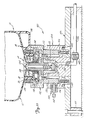
- FIG 17 is a sectional view which shows a portion of cover 210 and canister 208, together with a portion of container 10'.
- cover 210 includes a main cover plate 270, which carries an O-ring 272 for sealing cover plate 270 and the inner wall of canister of 208.
- the clamping or locking mechanism of cover 210 includes clamps 274, clamp ring 275, dowel pins 276, bearing blocks 278 and connecting ring 280.
- Clamping air cylinders 222A-222D are mounted between cover plate 270 and connecting ring 280. When air cylinders 222A-222D are actuated, their pistons move upward, lifting connecting ring 280.
- dome 282 Fixedly mounted in the center of main cover plate 270 is dome 282, which supports sleeve 284 and keycode cone 286.
- O-ring 288 provides a seal between cone 286 and the inner wall of dome 282.
- Shoulder bolts 290 connect together sleeve 284 and cone 286.
- Knob 236 is attached to the upper end of sleeve 284 by bolts 292.
- adjustable stop 294 The relative position of sleeve 284 and cone 286 with respect to dome 282 in an axial direction is determined by the position of adjustable stop 294.
- Lock nut 296 holds adjustable stop 294 in position.
- adjustable stop 294 The purpose of adjustable stop 294 is to allow system 200 to accommodate manufacturing tolerances in all parts.
- Sleeve 284 and cone 286 are permitted to rotate with respect to dome 282. Rotational forces apply to sleeve 284 and cone 286 by knob 236. This allows rotation of cone 286 so that key tabs 298 can be brought into alignment with the respective key slots in cap 80. As shown in Figure 17, dowel pins 300 hold key tab 298 on the inner surface of cone 286.
- Alignment pins 90 of cap 80 made with recesses 302 on the inner surface of cone 286 to assist in proper alignment of cone 286 with respect to cap 80.
- coupling 304 Coaxially mounted within sleeve 284 is coupling 304.
- the upper end of coupling 304 is connected to tubing conduit 230.
- probe 238 Connected at the lower end of coupling 304 is probe 238.
- O-ring 306 forms a seal between flange 308 of probe 238 and cone 286.
- Distal end 310 of probe 238 is pointed, and carries O-ring 312 which forms a seal with the neck region of fitment 14.
- Probe 238 has a T-shaped passage 314 which opens at distal end 310 and which is connected to valve chamber 316.
- valve chamber 316 Positioned within valve chamber 316 is a check valve formed by spring 318, disk 320 and poppet 322. Fluid passage 324 of coupling 304 connects the interior of valve chamber 316 with tubing conduit 230.
- Spring 318 biases poppet 322 to a normally closed position as shown in Figure 17.
- the fluid pressure causes poppet 322 to unseat, and allows fluid flow out of pouch 12 through passage 314, valve chamber 316 and passage 324 to the tubing conduit 230.
- coupling 304 and probe 238 do not rotate with knob 234, sleeve 284, and cone 286. This allows rotation to be applied to knob 236 in order to align key tabs 298 with their corresponding key slots in cap 80 without causing any rotation of probe 238.
- air pressure is applied to the interior of canister 208, and is permitted to enter the interior of bottle 16.
- the passageway for air flow is through the space between cap 80 and cone 286, which is provided in part by the notches or grooves of the periphery of cap 80.
- Air pressure tends to collapse pouch 12, which forces fluid out through probe 238 and coupling 304. Because the same air pressure is being applied both to the outer wall and the inner wall of bottle 16, wall strength of bottle 16 is not a factor in the ability to dispense fluid under pressure.
- the present invention provides an important alternative to prior art systems for handling and shipping liquid chemicals.
- the present invention provides a low cost, rugged, container which simplifies the disposal of parts coming into contact with the chemicals.
- the present invention is well suited for manual and automated dispensing in a safe manner which avoids any contact of the contents of the container with personnel and with the atmosphere.
Landscapes
- Engineering & Computer Science (AREA)
- Mechanical Engineering (AREA)
- Closures For Containers (AREA)
- Medical Preparation Storing Or Oral Administration Devices (AREA)
- Basic Packing Technique (AREA)
- Feeding, Discharge, Calcimining, Fusing, And Gas-Generation Devices (AREA)
- Containers And Packaging Bodies Having A Special Means To Remove Contents (AREA)
- Bag Frames (AREA)
Claims (9)
- Ein Flüssigchemikalien-Transportsystem, bestehend aus einem Behälter (10), mit:
einem elastischen Folienbeutel (12) mit Innenraum zur Aufnahme von Flüssigkeit;
einer Armatur (14), die dicht am Beutel (12) angeschlossen ist und eine Öffnung (22) hat, die eine Verbindung zum Innenraum des Beutels (12) bietet;
einer Flasche (16) mit einem Mund (36), die eine Verbindung zum Innenraum der Flasche (16) bietet; und
einer Verschlußkappe (20, 80), die den Mund (36) der Flasche (16) verschließt und über dem Mund (36) der Flasche (16) und der Armatur (14) positioniert wird;
gekennzeichnet durch die Integrierung von:
Dichtungsmitteln (60) für die Abdichtung der Öffnung (22), um atmosphärische Verschmutzung der Flüssigkeit zu unterbinden, nachdem der Beutel (12) über die Öffnung (22) mit Flüssigkeit gefüllt worden ist;
und einer Arretierungseinrichtung (18) für die Arretierung des Armaturenhalses (14) und der Mundinnenseite (56) der Flasche (16), mit Luftweg (54A, 54B), über den Luft in den Innenraum der Flasche (16) um den Beutel herum einströmen kann, wenn Flüssigkeit aus dem Beutel (12) geleert wird. - Ein Flüssigchemikalien-Transportsystem laut Anspruch 1, gekennzeichnet durch Arretierungsmittel (18), bestehend aus:
ersten und zweiten Sicherungssegmenten (40A, 40B); und Gelenkmitteln (42), welche die Segmente verbinden. - Ein Flüssigchemikalien-Transportsystem laut Anspruch 1 oder Anspruch 2, gekennzeichnet durch eine Armatur, bestehend aus:
einem Mundteil (22);
einem Flansch (24), am Mundteil angrenzend;
einem Halsteil (26), angeschlossen am Mundteil (22); und einem gewöhnlich konisch geformten Flanschteil (28), angeschlossen am Halsteil (26) und mit Beutel (12) dicht verschlossen. - Ein Flüssigchemikalien-Transportsystem laut Anspruch 3, gekennzeichnet dadurch, daß die Dichtungsmittel (60) eine Membran (60) beinhalten, die den Mund (22) der Armatur (4) abdeckt.
- Ein Flüssigchemikalien-Transportsystem laut den vorangegangenen Ansprüchen, gekennzeichnet dadurch, daß abgesehen von den Luftwegen (54A, 54B) in der Arretierungseinrichtung auch die Verschlußkappe (20, 80) über einen Luftweg (68) verfügt, über den Luft in den Innenraum der Flasche (16) um den Beutel (12) herum einströmen kann, wenn Flüssigkeit aus dem Beutel (12) entleert wird.
- Ein Flüssigchemikalien-Transportsystem laut Anspruch 1, gekennzeichnet dadurch, daß die Verschlußkappe (20, 80) eine zentrale Hauptöffnung (66) hat, die gewöhnlich mit der Öffnung (22) der Armatur ausgerichtet ist und abnehmbare Dichtungsmittel (62) besitzt, die die zentrale Hauptöffnung (66) bedecken.
- Ein Flüssigchemikalien-Transportsystem laut den vorangegangenen Ansprüchen, gekennzeichnet dadurch, daß der Luftweg (54A, 54B) der Arretierungseinrichtung (18) mit dem Mund (36) der Flasche verbunden ist, so daß Luft durch den Mund der Flasche und durch den Luftweg in den Innenraum der Flasche um den Beutel herum einströmen kann, wenn Flüssigkeit aus dem Beutel entleert wird.
- Ein Flüssigchemikalien-Transportsystem laut den vorangegangenen Ansprüchen, dadurch gekennzeichnet, daß die Arretierungseinrichtung (18) von der Armatur (14) getrennt ist, um von der Armatur (14) und dem Mund (36) der Flasche abgenommen werden zu können.
- Ein Flüssigchemikalien-Transportsystem laut den vorangegangenen Ansprüchen, daß außerdem durch einen Spender (200) gekennzeichnet ist, bestehend aus:
einem Heber (11), der durch die Dichtungsmittel (6) und in die Öffnung (22) eingesteckt werden kann, der Heber (110) hat einen Strömungsweg (138, 136, 314);
einer Einrichtung (104), die am Heber (110, 238) angeschlossen ist, zur Aufnahme von aus dem Beutel (12) und über den Strömungsweg (138, 136, 314) entleerte Flüssigkeit.
Applications Claiming Priority (3)
| Application Number | Priority Date | Filing Date | Title |
|---|---|---|---|
| US15601188A | 1988-02-16 | 1988-02-16 | |
| US156011 | 1988-02-16 | ||
| PCT/US1989/000615 WO1989007575A1 (en) | 1988-02-16 | 1989-02-15 | Container and dispensing system for liquid chemicals |
Publications (3)
| Publication Number | Publication Date |
|---|---|
| EP0408583A1 EP0408583A1 (de) | 1991-01-23 |
| EP0408583A4 EP0408583A4 (en) | 1991-07-24 |
| EP0408583B1 true EP0408583B1 (de) | 1995-11-15 |
Family
ID=22557709
Family Applications (1)
| Application Number | Title | Priority Date | Filing Date |
|---|---|---|---|
| EP89902903A Expired - Lifetime EP0408583B1 (de) | 1988-02-16 | 1989-02-15 | Behälter und verabreichungssystem für flüssige chemikalien |
Country Status (6)
| Country | Link |
|---|---|
| EP (1) | EP0408583B1 (de) |
| JP (1) | JPH0699000B2 (de) |
| AT (1) | ATE130282T1 (de) |
| CA (1) | CA1340347C (de) |
| DE (1) | DE68924847T2 (de) |
| WO (1) | WO1989007575A1 (de) |
Cited By (1)
| Publication number | Priority date | Publication date | Assignee | Title |
|---|---|---|---|---|
| US7896200B2 (en) | 2005-06-10 | 2011-03-01 | Panasonic Corporation | Liquid substance supplying device |
Families Citing this family (28)
| Publication number | Priority date | Publication date | Assignee | Title |
|---|---|---|---|---|
| DE4212434A1 (de) * | 1992-04-14 | 1993-10-21 | Henkel Kgaa | Anordnung zum Nachfüllen eines Behälters |
| GB2279069B (en) * | 1993-06-19 | 1997-03-05 | Archibald Gerard Mciver | Container |
| IE960204A1 (en) * | 1996-03-04 | 1997-09-10 | Loctite Ireland Ltd | Fluid flow connector and fluid pressure mechanism for fluids¹such as adhesives |
| IES80564B2 (en) * | 1997-02-04 | 1998-09-23 | Duras Trading Limited | A removable closure for a container |
| JP3929000B2 (ja) | 1998-05-08 | 2007-06-13 | アイセロ化学株式会社 | 高純度薬品液用容器 |
| JP2002126603A (ja) * | 2000-10-19 | 2002-05-08 | Kansai Paint Co Ltd | 圧送式塗料供給装置 |
| JP4926563B2 (ja) * | 2006-06-28 | 2012-05-09 | 東京応化工業株式会社 | 流体用容器及びそれを用いた流体入り容器 |
| EP2080709A1 (de) | 2008-01-15 | 2009-07-22 | InBev S.A. | Montage eines Behälters und eines Verschlusses |
| FR2955569B1 (fr) * | 2010-01-28 | 2012-01-20 | Arkema France | Dispositif constitue de futs connectes destine au transport de matieres dangereuses |
| JP5380584B1 (ja) * | 2012-06-28 | 2014-01-08 | 富士山の銘水株式会社 | プラスチックフィルム製の袋に液体を封入した液体袋から液体を取り出すための配管器具 |
| JP5982442B2 (ja) * | 2012-10-31 | 2016-08-31 | 富士フイルム株式会社 | 化学増幅型レジスト膜のパターニング用有機系処理液、並びに、これを使用したパターン形成方法、及び、電子デバイスの製造方法 |
| JP5764589B2 (ja) * | 2012-10-31 | 2015-08-19 | 富士フイルム株式会社 | 化学増幅型レジスト膜のパターニング用有機系処理液の収容容器、並びに、これらを使用したパターン形成方法及び電子デバイスの製造方法 |
| JP6495063B2 (ja) | 2015-03-26 | 2019-04-03 | Hoya株式会社 | レジスト液保管容器、レジスト液供給装置、レジスト液塗布装置、レジスト液保存装置、及びマスクブランクの製造方法 |
| US20200140175A1 (en) * | 2018-11-02 | 2020-05-07 | Entegris, Inc. | Multi piece fitment for a fluid container |
| JP7376610B2 (ja) | 2019-12-09 | 2023-11-08 | 富士フイルム株式会社 | 処理液、パターン形成方法 |
| US11661249B2 (en) | 2020-04-22 | 2023-05-30 | Entegris, Inc. | Multi piece fitment for a fluid container |
| EP3909484B1 (de) * | 2020-05-14 | 2023-12-13 | OP-Hygiene IP GmbH | Flaschenaufsatzpumpe |
| KR20230071181A (ko) * | 2020-10-22 | 2023-05-23 | 프리지오 아게 | 카트리지 시스템, 음료 조제기 및 카트리지 시스템을 제조하기 위한 공정 |
| EP4347428B1 (de) * | 2021-06-04 | 2026-04-29 | Hovina Inc. | Flüssigkeitsübertragungseinsatz, flüssigkeitsausgabevorrichtung und zugehörige verfahren |
| JP7011098B1 (ja) | 2021-06-14 | 2022-01-26 | 富士フイルムエレクトロニクスマテリアルズ株式会社 | 洗浄組成物、半導体基板の洗浄方法、および、半導体素子の製造方法 |
| JPWO2023140049A1 (de) | 2022-01-24 | 2023-07-27 | ||
| JP7145351B1 (ja) | 2022-03-25 | 2022-09-30 | 富士フイルム株式会社 | 組成物、半導体素子の製造方法 |
| US12539500B2 (en) | 2022-08-31 | 2026-02-03 | Sharkninja Operating Llc | Additive containers |
| CN119768898A (zh) | 2022-09-30 | 2025-04-04 | 富士胶片株式会社 | 药液、修饰基板的制造方法、层叠体的制造方法 |
| US12084334B2 (en) | 2022-11-17 | 2024-09-10 | Sharkninja Operating Llc | Ingredient container |
| US11871867B1 (en) | 2023-03-22 | 2024-01-16 | Sharkninja Operating Llc | Additive container with bottom cover |
| EP4683883A2 (de) * | 2023-03-22 | 2026-01-28 | SharkNinja Operating LLC | Additivbehälter |
| KR20250166218A (ko) | 2023-04-19 | 2025-11-27 | 후지필름 가부시키가이샤 | 처리액, 피처리물의 처리 방법 |
Family Cites Families (14)
| Publication number | Priority date | Publication date | Assignee | Title |
|---|---|---|---|---|
| US2191918A (en) * | 1938-10-15 | 1940-02-27 | Donald Colvin | Dispensing device |
| US2453080A (en) * | 1945-09-24 | 1948-11-02 | William A Shimp | Liquid measuring and dispensing apparatus |
| GB762567A (en) * | 1953-12-22 | 1956-11-28 | Giacomo Marcenaro | Closing means of plastic for metal or other vessels fitted with inner lines of plastic |
| US3876385A (en) * | 1972-07-31 | 1975-04-08 | Johns Manville | Fail-safe system for operating an autoclave door |
| US3883046A (en) * | 1974-02-11 | 1975-05-13 | Textron Inc | Elastomeric bladder for positive expulsion tank |
| US3952918A (en) * | 1974-03-18 | 1976-04-27 | Highland Laboratories | Fluid dispenser apparatus |
| US4098434A (en) * | 1975-06-20 | 1978-07-04 | Owens-Illinois, Inc. | Fluid product dispenser |
| US4165023A (en) * | 1977-07-21 | 1979-08-21 | Schmit Justin M | Fluid containing and dispensing structure having a deformable flexible wall portion |
| US4330066A (en) * | 1980-11-21 | 1982-05-18 | Robert Berliner | Receptacle with collapsible internal container |
| US4491247A (en) * | 1981-07-21 | 1985-01-01 | Nitchman Harold L | System, apparatus, and method of dispensing a liquid from a semi-bulk disposable container |
| US4445550B1 (en) * | 1982-08-20 | 1999-03-09 | Scholle Corp | Flexible walled container having membrane fitment for use with aseptic filling apparatus |
| JPS6013659A (ja) * | 1983-06-21 | 1985-01-24 | アサヒビール株式会社 | 飲料容器 |
| US4756347A (en) * | 1985-11-19 | 1988-07-12 | Jopado Baderi | Filling and dispensing valve, adapter and package |
| CA1291339C (en) * | 1986-07-15 | 1991-10-29 | Edgar P. Scragg | Device for dosing a flowing fluid |
-
1989
- 1989-02-15 AT AT89902903T patent/ATE130282T1/de not_active IP Right Cessation
- 1989-02-15 JP JP1502695A patent/JPH0699000B2/ja not_active Expired - Lifetime
- 1989-02-15 EP EP89902903A patent/EP0408583B1/de not_active Expired - Lifetime
- 1989-02-15 DE DE68924847T patent/DE68924847T2/de not_active Expired - Lifetime
- 1989-02-15 CA CA000591122A patent/CA1340347C/en not_active Expired - Fee Related
- 1989-02-15 WO PCT/US1989/000615 patent/WO1989007575A1/en not_active Ceased
Cited By (1)
| Publication number | Priority date | Publication date | Assignee | Title |
|---|---|---|---|---|
| US7896200B2 (en) | 2005-06-10 | 2011-03-01 | Panasonic Corporation | Liquid substance supplying device |
Also Published As
| Publication number | Publication date |
|---|---|
| WO1989007575A1 (en) | 1989-08-24 |
| CA1340347C (en) | 1999-01-26 |
| ATE130282T1 (de) | 1995-12-15 |
| EP0408583A4 (en) | 1991-07-24 |
| DE68924847T2 (de) | 1996-07-04 |
| JPH03502677A (ja) | 1991-06-20 |
| JPH0699000B2 (ja) | 1994-12-07 |
| DE68924847D1 (de) | 1995-12-21 |
| EP0408583A1 (de) | 1991-01-23 |
Similar Documents
| Publication | Publication Date | Title |
|---|---|---|
| US5102010A (en) | Container and dispensing system for liquid chemicals | |
| EP0408583B1 (de) | Behälter und verabreichungssystem für flüssige chemikalien | |
| CN101223100B (zh) | 流体储存和分配系统以及方法 | |
| EP2188190B1 (de) | Verfahren und vorrichtung zur ausgabe von fluiden | |
| US5526956A (en) | Liquid chemical dispensing and recirculating system | |
| US5957328A (en) | Liquid chemical dispensing and recirculating system | |
| US6206240B1 (en) | Liquid chemical dispensing system with pressurization | |
| EP0587412B1 (de) | Behälter für flüssige Chemikalien und Ausgabesystem | |
| AU691478B2 (en) | Dispensing closure for liquid containers | |
| WO1993017938A1 (en) | Vented, non-reusable, multi-dose cartridge | |
| CA2586722C (en) | Packaging assembly for flowable materials | |
| WO1995009126A1 (en) | Method for dispensing liquid from a multi-dose cartridge |
Legal Events
| Date | Code | Title | Description |
|---|---|---|---|
| PUAI | Public reference made under article 153(3) epc to a published international application that has entered the european phase |
Free format text: ORIGINAL CODE: 0009012 |
|
| 17P | Request for examination filed |
Effective date: 19900814 |
|
| AK | Designated contracting states |
Kind code of ref document: A1 Designated state(s): AT BE CH DE FR GB IT LI LU NL SE |
|
| A4 | Supplementary search report drawn up and despatched |
Effective date: 19910605 |
|
| AK | Designated contracting states |
Kind code of ref document: A4 Designated state(s): AT BE CH DE FR GB IT LI LU NL SE |
|
| 17Q | First examination report despatched |
Effective date: 19920930 |
|
| GRAA | (expected) grant |
Free format text: ORIGINAL CODE: 0009210 |
|
| RAP1 | Party data changed (applicant data changed or rights of an application transferred) |
Owner name: NOW TECHNOLOGIES INC. |
|
| AK | Designated contracting states |
Kind code of ref document: B1 Designated state(s): AT BE CH DE FR GB IT LI LU NL SE |
|
| PG25 | Lapsed in a contracting state [announced via postgrant information from national office to epo] |
Ref country code: IT Free format text: LAPSE BECAUSE OF FAILURE TO SUBMIT A TRANSLATION OF THE DESCRIPTION OR TO PAY THE FEE WITHIN THE PRESCRIBED TIME-LIMIT;WARNING: LAPSES OF ITALIAN PATENTS WITH EFFECTIVE DATE BEFORE 2007 MAY HAVE OCCURRED AT ANY TIME BEFORE 2007. THE CORRECT EFFECTIVE DATE MAY BE DIFFERENT FROM THE ONE RECORDED. Effective date: 19951115 Ref country code: FR Effective date: 19951115 Ref country code: LI Effective date: 19951115 Ref country code: NL Free format text: LAPSE BECAUSE OF FAILURE TO SUBMIT A TRANSLATION OF THE DESCRIPTION OR TO PAY THE FEE WITHIN THE PRESCRIBED TIME-LIMIT Effective date: 19951115 Ref country code: CH Effective date: 19951115 Ref country code: AT Effective date: 19951115 |
|
| REF | Corresponds to: |
Ref document number: 130282 Country of ref document: AT Date of ref document: 19951215 Kind code of ref document: T |
|
| REF | Corresponds to: |
Ref document number: 68924847 Country of ref document: DE Date of ref document: 19951221 |
|
| PG25 | Lapsed in a contracting state [announced via postgrant information from national office to epo] |
Ref country code: SE Effective date: 19960215 |
|
| PG25 | Lapsed in a contracting state [announced via postgrant information from national office to epo] |
Ref country code: LU Free format text: LAPSE BECAUSE OF NON-PAYMENT OF DUE FEES Effective date: 19960229 |
|
| EN | Fr: translation not filed | ||
| NLV1 | Nl: lapsed or annulled due to failure to fulfill the requirements of art. 29p and 29m of the patents act | ||
| REG | Reference to a national code |
Ref country code: CH Ref legal event code: PL |
|
| PLBE | No opposition filed within time limit |
Free format text: ORIGINAL CODE: 0009261 |
|
| STAA | Information on the status of an ep patent application or granted ep patent |
Free format text: STATUS: NO OPPOSITION FILED WITHIN TIME LIMIT |
|
| 26N | No opposition filed | ||
| REG | Reference to a national code |
Ref country code: GB Ref legal event code: 732E |
|
| BECA | Be: change of holder's address |
Free format text: 20000208 *ADVANCED TECHNOLOGY MATERIALS INC.:7 COMMERCE DRIVE, DANBURY CONNECTICUT 06810-4169 |
|
| REG | Reference to a national code |
Ref country code: GB Ref legal event code: IF02 |
|
| PGFP | Annual fee paid to national office [announced via postgrant information from national office to epo] |
Ref country code: GB Payment date: 20080213 Year of fee payment: 20 Ref country code: DE Payment date: 20080207 Year of fee payment: 20 |
|
| PGFP | Annual fee paid to national office [announced via postgrant information from national office to epo] |
Ref country code: BE Payment date: 20080417 Year of fee payment: 20 |
|
| REG | Reference to a national code |
Ref country code: GB Ref legal event code: PE20 Expiry date: 20090214 |
|
| PG25 | Lapsed in a contracting state [announced via postgrant information from national office to epo] |
Ref country code: GB Free format text: LAPSE BECAUSE OF EXPIRATION OF PROTECTION Effective date: 20090214 |