EP0408877A2 - Procédé pour déterminer la vitesse angulaire d'un moteur à combustion interne - Google Patents
Procédé pour déterminer la vitesse angulaire d'un moteur à combustion interne Download PDFInfo
- Publication number
- EP0408877A2 EP0408877A2 EP19900110423 EP90110423A EP0408877A2 EP 0408877 A2 EP0408877 A2 EP 0408877A2 EP 19900110423 EP19900110423 EP 19900110423 EP 90110423 A EP90110423 A EP 90110423A EP 0408877 A2 EP0408877 A2 EP 0408877A2
- Authority
- EP
- European Patent Office
- Prior art keywords
- signal
- generator
- internal combustion
- frequency
- combustion engine
- Prior art date
- Legal status (The legal status is an assumption and is not a legal conclusion. Google has not performed a legal analysis and makes no representation as to the accuracy of the status listed.)
- Granted
Links
- 238000002485 combustion reaction Methods 0.000 title claims abstract description 33
- 238000000034 method Methods 0.000 title claims abstract description 20
- 238000012545 processing Methods 0.000 claims abstract description 11
- 230000005540 biological transmission Effects 0.000 claims abstract description 7
- 230000003044 adaptive effect Effects 0.000 claims description 3
- 238000001914 filtration Methods 0.000 claims description 3
- 238000011161 development Methods 0.000 description 6
- 230000018109 developmental process Effects 0.000 description 6
- 230000010355 oscillation Effects 0.000 description 4
- 230000008569 process Effects 0.000 description 4
- 238000005259 measurement Methods 0.000 description 3
- 230000008901 benefit Effects 0.000 description 2
- 230000008859 change Effects 0.000 description 2
- 238000010586 diagram Methods 0.000 description 2
- 230000006870 function Effects 0.000 description 2
- 230000002123 temporal effect Effects 0.000 description 2
- 230000006978 adaptation Effects 0.000 description 1
- 235000019504 cigarettes Nutrition 0.000 description 1
- 230000006835 compression Effects 0.000 description 1
- 238000007906 compression Methods 0.000 description 1
- 230000007423 decrease Effects 0.000 description 1
- 238000001514 detection method Methods 0.000 description 1
- 238000004880 explosion Methods 0.000 description 1
- 238000010438 heat treatment Methods 0.000 description 1
- 230000036039 immunity Effects 0.000 description 1
- 230000005693 optoelectronics Effects 0.000 description 1
- 238000001228 spectrum Methods 0.000 description 1
- 230000001629 suppression Effects 0.000 description 1
- 238000012360 testing method Methods 0.000 description 1
Images
Classifications
-
- G—PHYSICS
- G01—MEASURING; TESTING
- G01P—MEASURING LINEAR OR ANGULAR SPEED, ACCELERATION, DECELERATION, OR SHOCK; INDICATING PRESENCE, ABSENCE, OR DIRECTION, OF MOVEMENT
- G01P3/00—Measuring linear or angular speed; Measuring differences of linear or angular speeds
- G01P3/42—Devices characterised by the use of electric or magnetic means
- G01P3/44—Devices characterised by the use of electric or magnetic means for measuring angular speed
- G01P3/48—Devices characterised by the use of electric or magnetic means for measuring angular speed by measuring frequency of generated current or voltage
Definitions
- the invention relates to a method for determining the speed of an internal combustion engine with a known number of cylinders.
- the invention has for its object to provide a simple method for determining the speed of an internal combustion engine with a known number of cylinders, which is particularly suitable for determining the speed of diesel internal combustion engines.
- the method according to the invention initially has the advantage of easy adaptation to the vehicle. All that is required is a connection to the electrical system of the motor vehicle, which can be done, for example, on the cigarette lighter. Since no special sensors are required, the device according to the invention is particularly suitable for determining the speed of diesel internal combustion engines.
- the speed can also be determined while driving.
- This application is gaining in importance in the context of the special exhaust gas test, which prescribes full-load operation in exhaust gas measurement for diesel vehicles and it cannot be assumed that each test center has a dynamometer at its disposal.
- the speed determination is particularly simple if the transmission ratio between the internal combustion engine and the generator driven by the internal combustion engine is determined from the ratio between a first signal component and a second low-frequency signal component of the pulsating current emitted by the generator or the pulsating voltage occurring at a load.
- the low-frequency signal component in the vehicle electrical system is caused by the discontinuous mode of operation of an internal combustion engine, caused by the combustion of the individual cylinders.
- the low-frequency frequency component is determined from the first signal component using a frequency modulation (FM) demodulator.
- FM frequency modulation
- the electrical signal tapped off, for example, from the vehicle electrical system is expediently subjected to signal filtering with a bandpass filter due to superimposed interference, which is caused in particular by the generator controller.
- signal filtering with a bandpass filter due to superimposed interference, which is caused in particular by the generator controller.
- the use of an adaptive filter, with which good interference suppression can be achieved over the entire useful bandwidth of the signal spectrum to be expected with a maximum ratio of useful signal / interference signal, has proven to be particularly advantageous.
- the method according to the invention it is provided to derive the first higher-frequency signal component of the on-board electrical system signal from the commutation vibrations which arise when a current supplied by a three-phase generator is commutated from one rectifier to the next rectifier.
- the low hardware outlay is advantageous because the entire signal processing and possibly the plausibility checks can be implemented as a program in the signal processing arrangement.
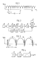
- FIG. 1 shows a voltage curve of an on-board electrical system of a motor vehicle supplied by a generator
- FIG. 2 shows a block diagram of a signal processing arrangement for determining the speed of an internal combustion engine of the motor vehicle
- FIG. 3 shows the signal curve shown in FIG. 1 with a higher temporal resolution
- FIG. 4 shows the block diagram a signal processing arrangement for determining a first signal component from the signal curve shown in FIG. 1 or FIG. 3.
- FIG. 1 shows the voltage curve U B of an on-board electrical system of a motor vehicle supplied by a generator. Only the AC voltage component is shown, with the omission of the significantly higher DC voltage component.
- the signal curve which is similar to a parabola, arises from rectification and superimposition of several phases of a generator designed as a three-phase generator. Instead of a three-phase generator with rectifiers, a direct current generator or an alternating current generator with one or more phases without a rectifier can also be provided.
- An alternating current generator can, for example, provide electrical energy for window heating or for other consumers that do not require direct current.
- the signal U B has a sinusoidal or sine-like curve compared to the curve shown in FIG.
- signal pieces are included which have a first higher-frequency signal component F1, the frequency of which can change slightly from arc to arc. This change is exaggerated in Figure 1 for clarity.
- the frequency changes of the first signal F1 repeat after the times T1, T2, T3 etc.
- the period between times T1 and T2 or T2 and T3 corresponds to a second low-frequency signal component F2 of the voltage curve U B , which is also included in all cases.
- the second signal component F2 arises from the working cycles of the internal combustion engine. Shortly before the times T1, T2, T3 etc., one cylinder of the internal combustion engine fires. The explosion process in the cylinder results in an increase in speed, which decreases again during the expansion phase until the next cylinder has ignited.
- FIG. 2 shows an internal combustion engine 10 which drives at least one generator 11.
- the generator 11 is provided to supply energy to an electrical system 12 of the motor vehicle.
- the signal U B is fed to a first signal filter 13, whose output signal is fed to both a first threshold level 14 and the filter 13 itself.
- the first signal component F1 occurs at the output of the first threshold value stage 14.
- the portion F1 is fed to both an averager 15 and an FM demodulator 16.
- the output signal of the FM demodulator 16 is passed on to a second threshold value stage 18 via a second signal filter 17.
- the second low-frequency signal component F2 occurs at the output of the second threshold value stage 18.
- a computing unit 20 which contains a memory 19, determines the speed n of the internal combustion engine from the component F2 and the averaged frequency component F1 as a function of a cylinder specification 21.
- FIG. 3 shows a section of the voltage curve U B shown in FIG. 1 with a higher resolution.
- the direct component was also omitted in FIG. 3.
- Short-term commutation oscillations 30 with the frequency F3 are present between the parabola-like signal components F1, which occur if a three-phase generator with rectifiers is provided.
- FIG. 4 shows part of a signal processing arrangement for determining the frequency F1.
- the voltage taken from the vehicle electrical system 12 is fed via a high-pass filter 40 to a monostable multivibrator 41, at the output of which the signal component F1 can be removed.
- the internal combustion engine 10 drives the generator 11, which is provided for supplying the vehicle electrical system 12.
- the generator 11 generates a single or multi-phase AC voltage, which is rectified and superimposed with the aid of diodes.
- a direct current generator or a Alternator can be provided without a rectifier.
- the signal curve of the vehicle electrical system voltage U B shown in FIG. 1 is produced, which contains an AC voltage component with a signal curve similar to a parabola or sinusoid.
- This characteristic signal curve can be derived both from the voltage drop across the internal resistance of the load in the vehicle electrical system 12 and from the current flowing through the load. If the generator 11 is designed for this purpose, it can also be operated without a load, the signal U B being taken directly from the generator 11.
- the speed determination is based on the fact that the frequency of the first signal component F1 is proportional to the speed of the internal combustion engine.
- the proportionality factor initially depends on the number of phases or number of poles of the generator 11, which are predefined. Furthermore, the proportionality factor depends on the transmission ratio between the internal combustion engine 10 and the generator 11 driven by the internal combustion engine 10. The gear ratio is generally not known and must first be determined.
- the signal U B is first subjected to bandpass filtering with the first filter 13 in the signal processing arrangement according to FIG.
- the filter 13 separates both unwanted low-frequency and high-frequency interference signals, such as those caused by the generator controller or by other switching processes in the vehicle electrical system 12.
- the first filter 13 is designed as an adaptive filter, for which an implementation as a digital filter or as a filter with switched capacities is particularly suitable.
- the bandpass filter is then conducted over the entire frequency band and For example, the output amplitude of the first filter 13 is evaluated by measuring the amplitude. Since the disturbances occur only sporadically, the ripple of the signal U B, however, is present continuously, it is possible in this way to correctly set the bandpass parameters of the digital filter or the filter with switched capacitances.
- the first threshold value stage 14 which is optionally provided, forms a rectangular signal from the signal component F1, which signal can be easily further processed. If the transmission ratio is known, the proportion F1 is directly a measure of the speed of the internal combustion engine.
- the signal U B has a second low-frequency signal component F2, which must first be determined.
- the signal component F2 comes about because the internal combustion engine 10 operates discontinuously with respect to a higher temporal resolution.
- the ignition processes of the individual cylinders of the internal combustion engine 10 lead to a quasi-periodic oscillation with the second frequency F2, which result from the quasi-periodic processes between the compression and expansion phases in the individual cylinders of the internal combustion engine 10. If the number of cylinders is known, the signal component F2 is also a direct measure of the speed of the internal combustion engine 10.
- the signal F1 is frequency modulated with the signal F2
- the signal F2 can be obtained from the signal with the frequency F1 by FM demodulation.
- the FM demodulator 16 and optionally the second bandpass filter 17 and possibly the second threshold stage 18 are therefore provided in the signal-processed arrangement.
- the second filter 17 frees the demodulated signal from interference and the second threshold stage 18 provides at the output an easily processable signal with the frequency F2 is available.
- the computing unit 20 determines the speed n from the ratio of the frequency F2 and F1 as a function of the cylinder specification 21 from the signal component F1 which is always present, the ratio of F2 to F1 is removed from the memory 19 by storing it at the start of the measurement, for example at idle speed of the internal combustion engine 10.
- the mean value generator 15 for the signal component with the frequency F1 is advantageously to be provided when the mean value of the speed n of the internal combustion engine is to be determined. In principle, it is also possible to arrange the averager 15 at the output of the computing unit 20.
- the signal component F1 is determined from the signal U B from the commutation oscillations 30 shown in FIG. 3 with the frequency F3.
- the vibrations 30 occur when the generator 11 is designed as an AC / three-phase generator with rectifiers.
- the signal U B taken from the vehicle electrical system is fed to a filter 40, which in the simplest case is designed as a high-pass filter, the lower limit frequency of which is tuned to the frequency F3.
- the output signal of the high-pass filter 40 is fed to a monostable multivibrator 41, which provides the possibility of re-triggering, so that the oscillation packets only trigger a single pulse at the output of multivibrator 41.
- the signal processing block (not shown in FIG. 4) can be subjected to a plausibility check on the output signal of the monostable multivibrator, which increases the immunity to interference. Useless or incorrect impulses could arise from switching operations of the generator regulator or from other electrical consumers in the motor vehicle.
- the signal processing arrangements 13 to 21, 40, 41 shown in FIGS. 2 and 4 can be implemented completely or partially as software in a computer.
Landscapes
- Physics & Mathematics (AREA)
- General Physics & Mathematics (AREA)
- Combined Controls Of Internal Combustion Engines (AREA)
- Testing Of Engines (AREA)
Applications Claiming Priority (2)
| Application Number | Priority Date | Filing Date | Title |
|---|---|---|---|
| DE3923532A DE3923532A1 (de) | 1989-07-15 | 1989-07-15 | Verfahren zur drehzahlermittlung einer brennkraftmaschine |
| DE3923532 | 1989-07-15 |
Publications (3)
| Publication Number | Publication Date |
|---|---|
| EP0408877A2 true EP0408877A2 (fr) | 1991-01-23 |
| EP0408877A3 EP0408877A3 (en) | 1991-03-20 |
| EP0408877B1 EP0408877B1 (fr) | 1993-10-13 |
Family
ID=6385174
Family Applications (1)
| Application Number | Title | Priority Date | Filing Date |
|---|---|---|---|
| EP90110423A Expired - Lifetime EP0408877B1 (fr) | 1989-07-15 | 1990-06-01 | Procédé pour déterminer la vitesse angulaire d'un moteur à combustion interne |
Country Status (4)
| Country | Link |
|---|---|
| EP (1) | EP0408877B1 (fr) |
| JP (1) | JP3130912B2 (fr) |
| DE (2) | DE3923532A1 (fr) |
| ES (1) | ES2047198T3 (fr) |
Cited By (15)
| Publication number | Priority date | Publication date | Assignee | Title |
|---|---|---|---|---|
| GB2294769A (en) * | 1994-11-04 | 1996-05-08 | Kai Leung Cheng | Engine rotational speed detection |
| US5640086A (en) * | 1994-09-06 | 1997-06-17 | Sun Electric Deutschland Gmbh | Tachometer based on electrical ripple and calibrated by mechanical engine signals |
| EP0780689A1 (fr) * | 1995-12-21 | 1997-06-25 | GRUNDIG Aktiengesellschaft | Procédé et montage de circuit pour déterminer la vitesse angulaire d'un moteur à combustion interne couplée à un générateur |
| EP0823637A1 (fr) * | 1996-08-07 | 1998-02-11 | Murata Manufacturing Co., Ltd. | Appareil de détermination de la vitesse d'un véhicule automobile par détermination des pulsations dans le signal d'un alternateur |
| EP0758087A3 (fr) * | 1995-07-31 | 1998-09-23 | Murata Manufacturing Co., Ltd. | Dispositif détecteur d'accélération capable de supprimer du signal du capteur d'accélération une composante de dérive indésirable |
| EP0872738A1 (fr) * | 1997-04-15 | 1998-10-21 | Robert Bosch Gmbh | Procédé pour la détermination de la fréquence de rotation d'un moteur à combustion interne |
| DE19720698A1 (de) * | 1997-05-16 | 1998-11-19 | Bosch Gmbh Robert | Anordnung zur Drehzahlmessung an einer Brennkraftmaschine |
| WO1998058263A1 (fr) * | 1997-06-13 | 1998-12-23 | Robert Bosch Gmbh | Procede pour determiner la vitesse de rotation d'un moteur a combustion interne |
| EP0895089A1 (fr) * | 1997-07-25 | 1999-02-03 | Robert Bosch Gmbh | Dispositif pour déterminer la vitesse de rotation d'un moteur à combustion interne |
| DE19732087A1 (de) * | 1997-07-25 | 1999-02-11 | Bosch Gmbh Robert | Vorrichtung zur Drehzahlbestimmung einer Brennkraftmaschine |
| DE19732089A1 (de) * | 1997-07-25 | 1999-02-11 | Bosch Gmbh Robert | Anordnung zur Bestimmung der Drehzahl einer Brennkraftmaschine |
| FR2888881A1 (fr) * | 2005-07-21 | 2007-01-26 | Kerlink Sa | Procede et dispositif de detection de l'etat du moteur d'un vehicule, vehicule et applications correspondants |
| DE19522271B4 (de) * | 1995-06-20 | 2007-04-26 | Robert Bosch Gmbh | Verfahren und Vorrichtung zur Diagnose eines Dieselmotors |
| DE102009045410A1 (de) | 2009-10-07 | 2011-04-14 | Robert Bosch Gmbh | Verfahren zur Drehzahlbestimmung |
| WO2017129330A1 (fr) * | 2016-01-27 | 2017-08-03 | Robert Bosch Gmbh | Détermination d'états de fonctionnement d'un moteur à combustion interne par un régulateur d'alternateur d'un moteur électrique accouplé au moteur à combustion interne |
Families Citing this family (10)
| Publication number | Priority date | Publication date | Assignee | Title |
|---|---|---|---|---|
| DE19713181A1 (de) * | 1997-03-27 | 1998-10-01 | Siemens Ag | Verfahren zum Bestimmen der Motordrehzahl eines Kraftfahrzeuges |
| DE19959939C2 (de) * | 1999-12-13 | 2003-04-17 | Siemens Ag | Verfahren zur Bestimmmung der Drehzahl einer Brennkraftmaschine |
| NZ523124A (en) | 2000-06-26 | 2004-08-27 | Snap On Tech Inc | Alternator testing method and system using timed application of load |
| DE10035463A1 (de) * | 2000-07-21 | 2002-01-31 | Audi Ag | Vergleichsvorrichtung in einem Kraftfahrzeug |
| DE10201422B4 (de) * | 2001-09-03 | 2015-06-18 | Prüfrex-Elektro-Apparatebau Inh. Helga Müller, geb. Dutschke | Verfahren und Anordnung zur Steuerung und/oder Diagnose einer Brennkraftmaschine |
| US7010460B2 (en) | 2003-10-30 | 2006-03-07 | Snap-On Incorporated | Reciprocating engine cylinder contribution tester and method |
| US7171302B2 (en) | 2004-05-07 | 2007-01-30 | Snap-On Incorporated | Determining engine cylinder contribution from indexed engine data |
| US7162397B2 (en) | 2004-05-07 | 2007-01-09 | Snap-On Incorporated | Decoding an alternator output signal |
| DE102012216616B4 (de) | 2012-09-18 | 2024-12-24 | Robert Bosch Gmbh | Verfahren und Vorrichtung zum Erkennen von Zündaussetzern bei einer Brennkraftmaschine eines Kraftfahrzeugs |
| DE102013217968B3 (de) * | 2013-09-09 | 2015-01-22 | Robert Bosch Gmbh | Phasenregelschleife, Generatorsteuereinrichtung und Verfahren zum Ansteuern eineselektrischen Antriebssystems eines Hybridfahrzeugs |
Family Cites Families (4)
| Publication number | Priority date | Publication date | Assignee | Title |
|---|---|---|---|---|
| FR2337886A1 (fr) * | 1976-01-06 | 1977-08-05 | Chauvin Arnoux Sa | Dispositif pour commander un convertisseur tachymetrique par la tension remanente d'un alternateur |
| DE2648382A1 (de) * | 1976-10-26 | 1978-04-27 | Volkswagenwerk Ag | Schaltungsanordnung zur gewinnung eines drehzahlsignals |
| DE3513937A1 (de) * | 1985-04-18 | 1986-10-23 | Robert Bosch Gmbh, 7000 Stuttgart | Verfahren zur ueberwachung eines drehzahlgeber-signals |
| EP0315357B1 (fr) * | 1987-11-03 | 1992-05-06 | Bear Automotive Service Equipment Company | Tachymètre |
-
1989
- 1989-07-15 DE DE3923532A patent/DE3923532A1/de not_active Withdrawn
-
1990
- 1990-06-01 ES ES90110423T patent/ES2047198T3/es not_active Expired - Lifetime
- 1990-06-01 DE DE90110423T patent/DE59003064D1/de not_active Expired - Lifetime
- 1990-06-01 EP EP90110423A patent/EP0408877B1/fr not_active Expired - Lifetime
- 1990-07-16 JP JP02185450A patent/JP3130912B2/ja not_active Expired - Fee Related
Cited By (21)
| Publication number | Priority date | Publication date | Assignee | Title |
|---|---|---|---|---|
| US5640086A (en) * | 1994-09-06 | 1997-06-17 | Sun Electric Deutschland Gmbh | Tachometer based on electrical ripple and calibrated by mechanical engine signals |
| USRE38100E1 (en) | 1994-09-06 | 2003-04-29 | Sun Electric Deutschland Gmbh | Tachometer based on electrical ripple and calibrated by mechanical engine signals |
| GB2294769A (en) * | 1994-11-04 | 1996-05-08 | Kai Leung Cheng | Engine rotational speed detection |
| DE19522271B4 (de) * | 1995-06-20 | 2007-04-26 | Robert Bosch Gmbh | Verfahren und Vorrichtung zur Diagnose eines Dieselmotors |
| EP0758087A3 (fr) * | 1995-07-31 | 1998-09-23 | Murata Manufacturing Co., Ltd. | Dispositif détecteur d'accélération capable de supprimer du signal du capteur d'accélération une composante de dérive indésirable |
| EP0780689A1 (fr) * | 1995-12-21 | 1997-06-25 | GRUNDIG Aktiengesellschaft | Procédé et montage de circuit pour déterminer la vitesse angulaire d'un moteur à combustion interne couplée à un générateur |
| US6220085B1 (en) | 1996-08-07 | 2001-04-24 | Murata Manufacturing Co., Ltd. | Vehicle-velocity calculating apparatus |
| EP0823637A1 (fr) * | 1996-08-07 | 1998-02-11 | Murata Manufacturing Co., Ltd. | Appareil de détermination de la vitesse d'un véhicule automobile par détermination des pulsations dans le signal d'un alternateur |
| EP0872738A1 (fr) * | 1997-04-15 | 1998-10-21 | Robert Bosch Gmbh | Procédé pour la détermination de la fréquence de rotation d'un moteur à combustion interne |
| DE19715643A1 (de) * | 1997-04-15 | 1998-10-22 | Bosch Gmbh Robert | Verfahren zur Ermittlung der Drehzahl einer Brennkraftmaschine |
| EP0881497A1 (fr) * | 1997-05-16 | 1998-12-02 | Robert Bosch Gmbh | Dispositif pour la détermination de la vitesse de rotation d'un moteur à combustion interne |
| DE19720698A1 (de) * | 1997-05-16 | 1998-11-19 | Bosch Gmbh Robert | Anordnung zur Drehzahlmessung an einer Brennkraftmaschine |
| WO1998058263A1 (fr) * | 1997-06-13 | 1998-12-23 | Robert Bosch Gmbh | Procede pour determiner la vitesse de rotation d'un moteur a combustion interne |
| EP0895089A1 (fr) * | 1997-07-25 | 1999-02-03 | Robert Bosch Gmbh | Dispositif pour déterminer la vitesse de rotation d'un moteur à combustion interne |
| DE19732087A1 (de) * | 1997-07-25 | 1999-02-11 | Bosch Gmbh Robert | Vorrichtung zur Drehzahlbestimmung einer Brennkraftmaschine |
| DE19732089A1 (de) * | 1997-07-25 | 1999-02-11 | Bosch Gmbh Robert | Anordnung zur Bestimmung der Drehzahl einer Brennkraftmaschine |
| DE19732088A1 (de) * | 1997-07-25 | 1999-02-11 | Bosch Gmbh Robert | Einrichtung zur Bestimmung der Drehzahl einer Brennkraftmaschine |
| FR2888881A1 (fr) * | 2005-07-21 | 2007-01-26 | Kerlink Sa | Procede et dispositif de detection de l'etat du moteur d'un vehicule, vehicule et applications correspondants |
| DE102009045410A1 (de) | 2009-10-07 | 2011-04-14 | Robert Bosch Gmbh | Verfahren zur Drehzahlbestimmung |
| WO2017129330A1 (fr) * | 2016-01-27 | 2017-08-03 | Robert Bosch Gmbh | Détermination d'états de fonctionnement d'un moteur à combustion interne par un régulateur d'alternateur d'un moteur électrique accouplé au moteur à combustion interne |
| CN108495989A (zh) * | 2016-01-27 | 2018-09-04 | 罗伯特·博世有限公司 | 通过与内燃机耦合的电机的发电机调节器确定内燃机的运行状态 |
Also Published As
| Publication number | Publication date |
|---|---|
| DE3923532A1 (de) | 1991-01-24 |
| EP0408877B1 (fr) | 1993-10-13 |
| ES2047198T3 (es) | 1994-02-16 |
| EP0408877A3 (en) | 1991-03-20 |
| JP3130912B2 (ja) | 2001-01-31 |
| JPH0356859A (ja) | 1991-03-12 |
| DE59003064D1 (de) | 1993-11-18 |
Similar Documents
| Publication | Publication Date | Title |
|---|---|---|
| EP0408877B1 (fr) | Procédé pour déterminer la vitesse angulaire d'un moteur à combustion interne | |
| DE69016708T2 (de) | Steuergerät für einen Fahrzeugwechselstromgenerator. | |
| EP0494171B1 (fr) | Procede de detection des irregularites de fonctionnement d'un moteur a combustion interne | |
| DE69034141T2 (de) | Steuerungssystem für einen Wechselstromgenerator eines Kraftfahrzeuges | |
| DE3028943C2 (de) | Steuereinrichtung für Brennkraftmaschinen | |
| DE3049305C2 (de) | Batterieladevorrichtung | |
| DE69029230T2 (de) | System zur Verringerung des Lärmpegels in Fahrzeugkabinen | |
| DE69024075T2 (de) | Einrichtung und Verfahren zur Steuerung von Schwingungen bei einem Automobilfahrzeug | |
| DE19547832C2 (de) | Verfahren und Schaltungsanordnung zur Drehzahlermittlung eines mit einem Generator gekoppelten Verbrennungsmotors | |
| DE3215683A1 (de) | Verfahren und einrichtung zum feststellen des motorklopfens | |
| DE4113743C2 (fr) | ||
| EP0472877A1 (fr) | Dispositif pour déterminer la vitesse angulaire d'un moteur à combustion interne | |
| DE102018200639A1 (de) | Verfahren und Vorrichtung zur Bestimmung einer Drehzahl einer Kurbelwelle ei-ner Brennkraftmaschine | |
| EP0477305B1 (fr) | Circuit de detection du cognement | |
| DE102005027650B4 (de) | Verfahren und Vorrichtung zum Betreiben einer Brennkraftmaschine | |
| DE102009037913A1 (de) | Verkürzung einer Anlauf-Sequenz | |
| DE29521352U1 (de) | Vorrichtung zur Drehzahlermittlung eines mit einem Generator gekoppelten Verbrennungsmotors | |
| DE3338271A1 (de) | Schaltung zur klopferkennung fuer ottomotoren | |
| DE4007202C2 (fr) | ||
| DE102017222863A1 (de) | Verfahren und Vorrichtung zur Bestimmung einer Drehwinkelposition einer Kurbelwelle einer Brennkraftmaschine | |
| DE2551683A1 (de) | Verfahren und vorrichtung zur funktionsueberpruefung von drehstromgeneratoren, insbesondere bei kraftfahrzeugen | |
| EP0500551B1 (fr) | Procede pour le controle de generatrices | |
| DE2648382A1 (de) | Schaltungsanordnung zur gewinnung eines drehzahlsignals | |
| DE3404019C2 (fr) | ||
| DE69615430T2 (de) | Verfahren und Vorrichtung zur Erkennung von Vibrationssignalen, z.B. dem Klopfen eines internen Verbrennungsmotors |
Legal Events
| Date | Code | Title | Description |
|---|---|---|---|
| PUAI | Public reference made under article 153(3) epc to a published international application that has entered the european phase |
Free format text: ORIGINAL CODE: 0009012 |
|
| AK | Designated contracting states |
Kind code of ref document: A2 Designated state(s): CH DE ES FR GB IT LI SE |
|
| PUAL | Search report despatched |
Free format text: ORIGINAL CODE: 0009013 |
|
| AK | Designated contracting states |
Kind code of ref document: A3 Designated state(s): CH DE ES FR GB IT LI SE |
|
| 17P | Request for examination filed |
Effective date: 19910821 |
|
| RAP3 | Party data changed (applicant data changed or rights of an application transferred) |
Owner name: ROBERT BOSCH GMBH |
|
| 17Q | First examination report despatched |
Effective date: 19920914 |
|
| GRAA | (expected) grant |
Free format text: ORIGINAL CODE: 0009210 |
|
| AK | Designated contracting states |
Kind code of ref document: B1 Designated state(s): CH DE ES FR GB IT LI SE |
|
| ET | Fr: translation filed | ||
| REF | Corresponds to: |
Ref document number: 59003064 Country of ref document: DE Date of ref document: 19931118 |
|
| GBT | Gb: translation of ep patent filed (gb section 77(6)(a)/1977) |
Effective date: 19931028 |
|
| ITF | It: translation for a ep patent filed | ||
| REG | Reference to a national code |
Ref country code: ES Ref legal event code: FG2A Ref document number: 2047198 Country of ref document: ES Kind code of ref document: T3 |
|
| PLBE | No opposition filed within time limit |
Free format text: ORIGINAL CODE: 0009261 |
|
| STAA | Information on the status of an ep patent application or granted ep patent |
Free format text: STATUS: NO OPPOSITION FILED WITHIN TIME LIMIT |
|
| 26N | No opposition filed | ||
| EAL | Se: european patent in force in sweden |
Ref document number: 90110423.2 |
|
| REG | Reference to a national code |
Ref country code: GB Ref legal event code: IF02 |
|
| PGFP | Annual fee paid to national office [announced via postgrant information from national office to epo] |
Ref country code: CH Payment date: 20050624 Year of fee payment: 16 |
|
| PGFP | Annual fee paid to national office [announced via postgrant information from national office to epo] |
Ref country code: ES Payment date: 20050628 Year of fee payment: 16 |
|
| PGFP | Annual fee paid to national office [announced via postgrant information from national office to epo] |
Ref country code: SE Payment date: 20050629 Year of fee payment: 16 |
|
| PG25 | Lapsed in a contracting state [announced via postgrant information from national office to epo] |
Ref country code: ES Free format text: LAPSE BECAUSE OF NON-PAYMENT OF DUE FEES Effective date: 20060602 Ref country code: SE Free format text: LAPSE BECAUSE OF NON-PAYMENT OF DUE FEES Effective date: 20060602 |
|
| PG25 | Lapsed in a contracting state [announced via postgrant information from national office to epo] |
Ref country code: LI Free format text: LAPSE BECAUSE OF NON-PAYMENT OF DUE FEES Effective date: 20060630 Ref country code: CH Free format text: LAPSE BECAUSE OF NON-PAYMENT OF DUE FEES Effective date: 20060630 |
|
| REG | Reference to a national code |
Ref country code: CH Ref legal event code: PL |
|
| EUG | Se: european patent has lapsed | ||
| REG | Reference to a national code |
Ref country code: ES Ref legal event code: FD2A Effective date: 20060602 |
|
| PGFP | Annual fee paid to national office [announced via postgrant information from national office to epo] |
Ref country code: FR Payment date: 20090618 Year of fee payment: 20 |
|
| PGFP | Annual fee paid to national office [announced via postgrant information from national office to epo] |
Ref country code: DE Payment date: 20090825 Year of fee payment: 20 Ref country code: GB Payment date: 20090623 Year of fee payment: 20 |
|
| PGFP | Annual fee paid to national office [announced via postgrant information from national office to epo] |
Ref country code: IT Payment date: 20090626 Year of fee payment: 20 |
|
| PG25 | Lapsed in a contracting state [announced via postgrant information from national office to epo] |
Ref country code: GB Free format text: LAPSE BECAUSE OF EXPIRATION OF PROTECTION Effective date: 20100531 |
|
| PG25 | Lapsed in a contracting state [announced via postgrant information from national office to epo] |
Ref country code: DE Free format text: LAPSE BECAUSE OF EXPIRATION OF PROTECTION Effective date: 20100601 |