EP0408919A2 - Dispositif d'alimentation de poudre - Google Patents
Dispositif d'alimentation de poudre Download PDFInfo
- Publication number
- EP0408919A2 EP0408919A2 EP90111783A EP90111783A EP0408919A2 EP 0408919 A2 EP0408919 A2 EP 0408919A2 EP 90111783 A EP90111783 A EP 90111783A EP 90111783 A EP90111783 A EP 90111783A EP 0408919 A2 EP0408919 A2 EP 0408919A2
- Authority
- EP
- European Patent Office
- Prior art keywords
- powder
- container
- toner
- transportation
- supply opening
- Prior art date
- Legal status (The legal status is an assumption and is not a legal conclusion. Google has not performed a legal analysis and makes no representation as to the accuracy of the status listed.)
- Granted
Links
Images




Classifications
-
- G—PHYSICS
- G03—PHOTOGRAPHY; CINEMATOGRAPHY; ANALOGOUS TECHNIQUES USING WAVES OTHER THAN OPTICAL WAVES; ELECTROGRAPHY; HOLOGRAPHY
- G03G—ELECTROGRAPHY; ELECTROPHOTOGRAPHY; MAGNETOGRAPHY
- G03G15/00—Apparatus for electrographic processes using a charge pattern
- G03G15/06—Apparatus for electrographic processes using a charge pattern for developing
- G03G15/08—Apparatus for electrographic processes using a charge pattern for developing using a solid developer, e.g. powder developer
-
- G—PHYSICS
- G03—PHOTOGRAPHY; CINEMATOGRAPHY; ANALOGOUS TECHNIQUES USING WAVES OTHER THAN OPTICAL WAVES; ELECTROGRAPHY; HOLOGRAPHY
- G03G—ELECTROGRAPHY; ELECTROPHOTOGRAPHY; MAGNETOGRAPHY
- G03G15/00—Apparatus for electrographic processes using a charge pattern
- G03G15/06—Apparatus for electrographic processes using a charge pattern for developing
- G03G15/08—Apparatus for electrographic processes using a charge pattern for developing using a solid developer, e.g. powder developer
- G03G15/0822—Arrangements for preparing, mixing, supplying or dispensing developer
- G03G15/0877—Arrangements for metering and dispensing developer from a developer cartridge into the development unit
- G03G15/0881—Sealing of developer cartridges
- G03G15/0882—Sealing of developer cartridges by a peelable sealing film
-
- G—PHYSICS
- G03—PHOTOGRAPHY; CINEMATOGRAPHY; ANALOGOUS TECHNIQUES USING WAVES OTHER THAN OPTICAL WAVES; ELECTROGRAPHY; HOLOGRAPHY
- G03G—ELECTROGRAPHY; ELECTROPHOTOGRAPHY; MAGNETOGRAPHY
- G03G15/00—Apparatus for electrographic processes using a charge pattern
- G03G15/06—Apparatus for electrographic processes using a charge pattern for developing
- G03G15/08—Apparatus for electrographic processes using a charge pattern for developing using a solid developer, e.g. powder developer
- G03G15/0822—Arrangements for preparing, mixing, supplying or dispensing developer
- G03G15/0865—Arrangements for supplying new developer
- G03G15/0875—Arrangements for supplying new developer cartridges having a box like shape
-
- G—PHYSICS
- G03—PHOTOGRAPHY; CINEMATOGRAPHY; ANALOGOUS TECHNIQUES USING WAVES OTHER THAN OPTICAL WAVES; ELECTROGRAPHY; HOLOGRAPHY
- G03G—ELECTROGRAPHY; ELECTROPHOTOGRAPHY; MAGNETOGRAPHY
- G03G15/00—Apparatus for electrographic processes using a charge pattern
- G03G15/06—Apparatus for electrographic processes using a charge pattern for developing
- G03G15/08—Apparatus for electrographic processes using a charge pattern for developing using a solid developer, e.g. powder developer
- G03G15/0822—Arrangements for preparing, mixing, supplying or dispensing developer
- G03G15/0877—Arrangements for metering and dispensing developer from a developer cartridge into the development unit
-
- G—PHYSICS
- G03—PHOTOGRAPHY; CINEMATOGRAPHY; ANALOGOUS TECHNIQUES USING WAVES OTHER THAN OPTICAL WAVES; ELECTROGRAPHY; HOLOGRAPHY
- G03G—ELECTROGRAPHY; ELECTROPHOTOGRAPHY; MAGNETOGRAPHY
- G03G2215/00—Apparatus for electrophotographic processes
- G03G2215/08—Details of powder developing device not concerning the development directly
- G03G2215/0802—Arrangements for agitating or circulating developer material
- G03G2215/0816—Agitator type
- G03G2215/0827—Augers
- G03G2215/083—Augers with two opposed pitches on one shaft
-
- Y—GENERAL TAGGING OF NEW TECHNOLOGICAL DEVELOPMENTS; GENERAL TAGGING OF CROSS-SECTIONAL TECHNOLOGIES SPANNING OVER SEVERAL SECTIONS OF THE IPC; TECHNICAL SUBJECTS COVERED BY FORMER USPC CROSS-REFERENCE ART COLLECTIONS [XRACs] AND DIGESTS
- Y10—TECHNICAL SUBJECTS COVERED BY FORMER USPC
- Y10S—TECHNICAL SUBJECTS COVERED BY FORMER USPC CROSS-REFERENCE ART COLLECTIONS [XRACs] AND DIGESTS
- Y10S222/00—Dispensing
- Y10S222/01—Xerography
Definitions
- the present invention relates to an apparatus for supplying powder. More particularly, the present invention relates to an apparatus for supplying stored powder to, for example, a transportation path.
- the developing unit of a copying machine has a toner hopper (referred to as hopper below) for storing supply toner.
- a hopper thereof usually has a bottom portion which is V-shaped in a sectional side view, formed by sloping inner surfaces. The stored toner moves down along the inner surfaces to the bottom portion. Then, as described in U.S. Pat. No. 4,803,513 and U.S. Pat. No. 4,422,750, the toner is transported further down, to the casing of the developing unit, by the rotation of a supply roller provided in the bottom part of the hopper.
- a more moderate slope of the inner surfaces is preferred. This is due to the fact that a hopper having more gently sloping surfaces can contain a greater amount of toner. However, should the angles of the slopes be too reduced, toner in 'the hopper may not fall, wherein the toner would remain in the hopper and, furthermore, may deteriorate. At the same time, if the slopes of the hopper have too great an angle, the hopper can contain only a small amount of toner, though the toner does readily drop Furthermore, the toner may form a bridge in a hopper having very steep slopes. The bridge causes a gap between the bulk of toner to be supplied and the supply roller, thereby interrupting the toner supply.
- Japanese Patent Lay -Open No. 22367/1986 discloses a developing unit which comprises a developing device and a hopper separate from the developing device.
- This separable type developing unit must have transportation means in the hopper for transporting toner to a connection path between the hopper and the developing device.
- the transportation means usually consists of rotatable member such as a spiral. Moreover, it may be presumed that if the rotating spiral agitates the toner, there would be little toner remnant in a hopper having moderate slopes inside for storing a greater amount of toner.
- Such problems concerning the slope angles in a hopper, or problems concerning the contradiction with regard to the volume of stored powder as against remnant powder in the container, may occur not only in a toner hopper for use in the developing unit, but also in various other kinds of hoppers for storing other kinds of powder.
- a developing unit having a developing device and a hopper separate from the developing device to improve operation efficiency has been proposed.
- the hopper may be designed for placement in a suitable position.
- a long toner transportation path such as a pipe, must be provided.
- Such a structure requires an opening in the bottom or a side of the hopper to supply toner to the transportation path.
- an apparatus for supplying powder comprises a container, a transportation member and a swing plate.
- the container has sloping inner walls and contains powder.
- the transportation member is placed rotatably at the bottom of the container, for transporting the powder in the predetermined direction.
- the swing plate is affixed to one of the sloping inner walls. The bottom end of the swing plate is positioned in the locus of the transporting member when the transportation rod rotates, whereby the swing plate is swung by the rotation of the transportation rod.
- the transportation member may include a rod having a spiral thereon, and/or a rotor having a plurality of wings thereon.
- the powder contained in the container falls along the upper surface of the swing plate provided on the inner wall of the container.
- the powder in the bottom is transported by the transportation member in the predetermined direction.
- the rotation of the transportation member causes the swing plate to swing. Therefore, even if the slope of the inner surface of the container is moderate whereby the container may store a greater amount of powder, the powder readily drops to the bottom by the swinging of the plate. Accordingly, little powder is remnant in the container.
- an apparatus for supplying powder comprises a container, a transportation member and a rotation member.
- the container is for containing powder and has a supply opening at the bottom to allow the powder to drop therethrough.
- the transportation member is for transporting the powder from the container to the supply opening.
- the rotation member is both for closing the supply opening and for allowing, by its rotation, the powder to drop through the supply opening.
- the powder in the container is transported to the supply opening located in the bottom of the container. Since the supply opening is formed in the bottom of the container, the transportation length of the powder is thereby shorter than that of a conventional container having a supply opening in the side wall, whereby little powder is remnant in the end of the container, and whereby little adheres to it.
- the supply opening of the container is covered by the rotation member, and moreover the rotation of the rotation member supplies the powder. Therefore, excess powder cannot fall through the supply opening, and a proper amount of powder is supplied to the transportation path through the supply opening by the rotation member.
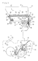
- Fig. 1 shows the outline of the structure of an electrostatic-process copying machine having a toner hopper as an apparatus for supplying powder in accordance with an embodiment of the present invention.
- a machine body 1 consists of the upper portion 1a and the lower portion 1b.
- the upper portion 1a can pivot on a hinge 18 at the left side of the figure to open the machine body 1.
- the machine body 1 has a contact glass 2 in the upper surface and an original holder 3 thereon which can be opened.
- detachable paper cassette cases 4 and 5 are attached on the right side of the machine body in the figure.
- a copy tray 6 is attached wherein copied paper is received.
- an optical exposure system 7 for obtaining information from the original image is located in the upper portion 1a.
- the exposure system 7 consists of a light source, mirrors and lenses.
- a photoconductive drum 8 Disposed, as a photoconductor, in the central part of the lower portion lb is a photoconductive drum 8, as a photoconductor, on which an electrostatic image is formed.
- an image forming part Surrounding the photoconductive drum 8, there is an image forming part which consists of a corona-generating device 9 for charging the photoconductive drum 8 with a predetermined level of electric charge, a developing unit 10 for developing an electrostatic image, a transfer unit 11 for transferring a toner image to paper, a detach unit 12 for detaching paper from the photoconductive drum 8, and a cleaning unit 13 for removing toner from the photoconductive drum 8, in that order.
- a paper transferring path 14 is provided between the paper cassette cases 4 and 5 and the image forming part.
- a paper transportation device 15 In a part of the paper stream lower than the image forming part, a paper transportation device 15 is provided.
- a fixing unit 16 for fixing a transferred image on the fed paper is disposed between the paper transferring device 15 and the copy tray 6. Beyond the fixing unit 16 in the paper flow, a pair of rollers 17 are provided for disposing of paper to the copy tray 6.
- the developing unit 10 consists mainly of a developing device 20 and a hopper 21 for supplying toner to the developing device 20.
- the developing device 20 consists of a body 20d and a supply part 20c on the body 20d (shown in Fig. 2).
- the developing device 20 is placed between a front plate 22 and a back plate (not shown), where the side of the copying machine closer to an operator is referred to as the front side and the side opposite is referred to as the back side.
- the developing device 20 is slidable in the direction perpendicular to the axis of the photoconductive drum 8, or upward in this embodiment, to be attached and detached.
- the front plate 22 located at the front in the lower part 1b is pivotable upward, or clockwise, on a fulcrum 23, from the position shown in Fig. 3.
- the back plate, located at the back in the lower portion 1b, is pivotable in the same manner as the front plate 22.
- guides 24 and 25 for guiding the developing device 20 to the predetermined position are formed on the inside of the front plate 22 and of the back plate. Meanwhile, the developing device 20 has support members 26 and 27 on its side walls which project into the guides 24 and 25. The support members 26 and 27 are supported by a first pocket P1 and a second pocket P2 formed by the guides 24 and 25.
- an inside surface of the guide 25 supporting the support member 26 of the developing device 20 comprises a part of an arc of radius R whereof the center coincides with to the axis of the photoconductive drum 8.
- a handle 28 is attached to the upper part of the developing device 20 in order to draw up the developing device 20.
- the developing device 20 has in its body 20d a developing roller 29 for supplying toner to the photoconductive drum 8, a scooping rotor 30 for scooping developer consisting of toner and carrier to the developing roller 29, and an agitation roller 31 for agitating the developer in the developing device 20, all of which are rotatable.
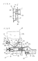
- a spiral 32 shown in Figs. 5 and 6, is rotatably provided for transferring toner supplied from the hopper 21, described below, in the lateral direction of the developing device 20.
- an opening 20a connected to the hopper 21 is formed in the front wall of the supply part 20c above the spiral 32, as shown in Figs. 5 and 6.
- a link member 34 is pivotally connected with a pin 33 to the upper part of the left end, in Fig. 3, of the front plate 22 which supports the developing device 20 and the photoconductive drum 8.
- the upper end of the link member 34 is pivotally connected to the upper portion 1a of the copying machine body 1.
- the hopper 21 is disposed in the front of the developing device 20 and fixed to the front plate 22 with supporting plates 35 and 36.
- the hopper 21 consists mainly of a hopper body 37 and a cartridge 42.
- the hopper body 37 has a toner container 38 for containing toner.
- the toner container 38 has a pair of inside walls at both ends in the widthwise direction, which slope to make a "V", as in the sectional side view, and another pair of inside walls at both ends in the direction perpendicular to the widthwise direction, which slope as well. Accordingly the container 38 opens out at its upper end.
- the toner container 38 has holders 40 and 41, whereof the sectional shape is similar to a "C", at the upper left and right ends.
- the holders 40 and 41 hold a flange 43 surrounding the opening of the toner cartridge 42, as described below.
- another holder 44 is formed in the rear portion of the toner container 38.
- the holder 44 holds the flange 43 of the toner cartridge 42 similarly by the holders 40 and 41.
- a toner supply opening 38a for allowing toner to drop is formed at the bottom of the toner container 38.
- the toner supply opening 38a is formed slightly on the right (in Fig. 3) of the middle in the lengthwise direction of the toner container 38 to correspond to the connecting opening 20a of the developing device 20, as in the view in Fig. 3.
- a transfer means 39 is disposed to transfer the toner in the container 38 to the opening 38a.
- the transfer means 39 consists of a rod 39d and a transfer member.
- the transfer member consists of a rotor 39a having four wings 45, above the toner supply opening 38a, and a pair of spirals 39b and 39c on either side of the rotor 39a and opposite to each other in terms of twisting direction, for transferring the toner to the rotor 39a.
- the rotor 39a covers the toner supply opening 38a with its wings 45 whereby an excessive amount of toner cannot be supplied at a given time.
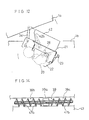
- FIG. 8 placed on a pair of sloping walls of the toner container 38 are side swing plate 46 (one of which is shown in Fig. 8), a front swing plate 47 and a rear swing plate 48 (as an auxiliary swing plate), made of elastic material such as polyester film.
- Each swing plate 46 is attached to the inside surface of the container 38 at its upper portion, leaving its lower portion free.
- Each bottom end of the side swing plates 46 is on an end of the spiral 39b and 39c.
- the bottoms of the side portions of the rear swing plate 48 are placed on the side swing plates 46 so that the rear swing plate 48 is swung by the oscillation of the side swing plates 46.
- Part of the bottom portion of the front swing plate 47 has a projection 47a.
- the projection 47a is placed on the wing 45 adjacent to the front swing plate 47, as shown in Figs. 8-10.
- the direction of the rotation of the transfer means 39 as shown with an arrow A in Figs. 8 and 10 is predetermined whereby the projection 47a cannot be bent down towards the opening 38a.
- a cylindrical casing 49 provided below the toner container 38 extends in the direction perpendicular to the transfer member 39.
- a toner supply pipe 50 is slidably inserted.
- An upper opening 50a is formed in the upper portion of the toner supply pipe 50.
- the opening 50a always connects the inside of the pipe 50 and the toner supply opening 38a of the toner container 38, regardless of where the toner supply pipe 50 is located within its range of sliding.
- a lower opening 50b is formed circumferentially in the lower half of the pipe 50, (at the right end in Fig. 5).
- a spiral 51 is provided rotatably in the pipe 50, whereby toner dropped from the toner container 38 is transported to the end of the toner supply pipe 50.
- a rod 51a of the spiral 51 protrudes from the hopper 21 through the end of the operator side (or the left side in Fig. 5) of the toner supply pipe 50 and the end of the cylindrical casing 49.
- Fig. 5 when the front cover 19 of the machine body 1 is closed, the front cover 19 pushes the end of the rod 51a with its inner surface. Accordingly, the toner supply pipe 50 is pushed into the machine body 1, and the other end of the pipe 50 moves into the opening 20a of the developing device 20.
- a cover 52 slidably fits onto the tip-end portion of the toner supply pipe 50.
- the cover 52 can move along the toner supply pipe 50 and is always tensioned toward the other end of the toner supply pipe 50 by a spring 53.
- a drive gear 55 is connected to a drive motor 54 in the right (in Fig. 3) end part of the hopper 21.
- the drive gear 55 is connected to the rod 39d of the transfer member 39 through a first link gear 56 and a gear 57 for toner supply.
- the first link gear 56 is connected to a first bevel gear 58
- the bevel gear 58 is connected to a small gear 61 via a second bevel gear 59 and a second link gear 60 integrally formed thereon.
- the small gear 61 is fixed to the rod 51a extending outward from the hopper 21, accordingly thereby, the drive gear 55 drives the spiral 51.
- the toner cartridge 42 is for storing toner and supplying the toner to the toner container 38.
- the toner cartridge 42 consists of a cartridge body 42a, a seal member 62 and a rolling-up nechanism.
- the cartridge body 42a is box-shaped and has an opening 66 at the bottom end. There are sloping walls in the lower part of the cartridge body 42a whereof the lower ends are closer to each other than the upper ends.
- the flange 43 is formed at the bottom end, as described above, and is slid into the holders 40 and 41 of the hopper body 37 when the cartridge 42 is to be attached to or detached from the hopper body 37. As shown in Fig. 5, there is a hole 43a for locking, into which a locking projection 38b of the toner container 38 is engaged to fix the toner cartridge 42, when the cartridge body 42a is set onto the hopper body 37.
- the cartridge 42 has the opening 66 closed by the folded seal member 62 before use.
- On the flange 43 there is a mechanism with which the seal member 62 is rolled up, when the cartridge body 42a is set onto the hopper body 37.
- the mechanism consists of a supporter 63, a roller 64 and a pressing member 65.
- the supporter 63 is formed integrally on the operator-side part of the flange 43.
- the supporter 63 has a U-shaped notch 63a into which the roller 64 is received rotatably.
- the folded seal member 62 is adhered to the roller 64 at the free end.
- the roller 64 has a crank-shaped end portion 64a for handling, referred to as a roll-up handle.
- the pressing member 65 made of resin having a sponge-like elasticity, extends in the lengthwise direction of the seal member 62 along the roller 64. The pressing member 65 presses on the outer surface of the seal member 62 when it is rolled by the roller 64.
- the hopper 21 is fixed to the developing device 20 and then the front cover 19 is closed.
- the end portion of the toner supply pipe 50 is inserted into the connecting opening 20a of the developing device 20, because the inside surface of the front cover 19 pushes the rod 51a toward the right (in Fig. 5).
- the end of the cover 52 on the toner supply pipe 50 touches the edge of the opening 20a of the developing device 20, and thereupon the cover 52 is moved backward in relation to the toner supply pipe 50, pressing the spring 53, to open the lower opening 50b of the toner supply pipe 50.
- the transporting route of toner is shown in Fig. 7.
- the spiral 32 of the developing device 20 is continually rotated by a driving system, not shown. However, the transfer means 39 and the spiral 51 of the hopper 21 are usually stopped.
- the drive motor 54 starts and the drive gear 55 of the hopper 21 rotates.
- the rotation of the drive gear 55 is transferred to the transfer means 39 through the first link gear 56 and the toner supply gear 57.
- the transfer means 39 rotates, one portion of toner in the left side (in Fig. 3) is transported by the spiral part 39b, and another portion in the right side (in Fig. 3) is transported by the spiral part 39c to the rotor 39a, respectively.
- the rotor 39a permits a constant amount of toner to go down through the toner supply opening 38a, by means of the wings 45.
- the toner supplied to the toner supply part 20c of the developing device 20 is transported in the longitudinal direction of the supply part 20c by the spiral 32. Since a slot 20b extends in the longitudinal direction below the spiral 32, the toner is supplied through the slot 20b to the agitation roller 31 and the scooping rotor 30. Then, when the concentration of toner reaches a predetermined level, the toner supply instruction stops, and the drive motor 54 of the hopper 21 stops, thereby halting the toner supply operation.
- the toner supply opening 38a is located not at the end, but in the middle of the hopper 21, the transportation distance of toner in the toner container 38 is thereby short. Therefore, the residence time of toner located at the lateral ends of the container 38 in the beginning is reduced, so that less amount of toner can adhere to the inner surfaces of the container 38.
- the rotor 39a of the transfer means 39 permits only the predetermined amount of toner to fall through the opening 38a, and this rotor 39a closes the opening 38a with its wings 45 when the rotor 39a stops. Therefore, the toner cannot be oversupplied, and thereby neither an excessive-toner problem nor a spreading-toner problem can occur.
- the rod 39d rotates to rotate the spiral part 39b. Since the spiral part 39b contacts the bottom ends of the side swing plates 46 towards each of its ends, the bottom ends of the swing plates 46 are alternately pushed up by the spiral and not pushed while the spiral 39b is rotating. As a result, the bottom parts of the side swing plates 46 pivot on the upper part. Furthermore, the rear swing plate 48 also swings by the oscillation of the side suing plates 46, since both side ends of the rear swing plate 48 are on the side swing plates 46.
- the front swing plate 47 also swings similarly to the above, since the projection 47a of the front swing plate 47 is on one of the wings 45, and the bottom end of the front swing plate 47 is pushed up by the wings 45, and not contrariwise, due to the rotation of the rotor 39a.
- the swing plates 46-48 swing against the four slopes in the toner container 38 when the toner is supplied, so that the toner in the toner container 38 can move down to the bottom, thereby not remaining on the slopes.
- the operation will be described as when the developing device 20 is exchanged to change developing colors.
- the hopper 21 usually contains toner of a particular color such as black, which is the most frequently used.
- the lock between the upper portion 1a and the lower portion 1b of the machine body 1 in Fig. 1 is opened, and the upper portion 1a is rotated in the counterclockwise direction about the hinge 18 to open the body 1. Opening the upper portion 1a pulls up the link member 34, so that the front plate 22 and the rear plate, connected to the link members 34 with the pins 33, rotate clockwise about the fulcra 23.
- the situation herewith is shown in Fig. 12. Under the condition of Fig. 12, the developing device 20 is able to come out upward from the machine body.
- the rod 51a of the hopper 21 is pulled toward the operator, so that the rod 51a, the spiral 51 and the toner supply pipe 50 move to the left (in Fig. 5, as shown with phantom lines).
- the right end portion of the toner supply pipe 50 comes out from the opening 20a of the developing device 20 so that the hopper 21 and the developing device 20 are disconnected.
- the developing device 20 is pulled up by grasping the handle 28, so that the support members 26 and 27 come out from the pockets P1 and P2 of the side plates, and the developing device 20 slides up along the guides 24 and 25 to the outside of the machine body 1.
- a red developing device 20 which contains red toner, for example, is inserted into the machine body 1, and the support members 26 and 27 are made to go down along the guides 24 and 25 of the plate 22. Thereby, the support members 26 and 27 are supported by the pockets P1 and P2. Since the surface of the guide 25 supporting the support member 26 is a part of the arc of radius R whereof the center coincides with that of the photoconductive drum 8, the distance between the developing roller 29 and the photoconductive drum 8 is maintained strictly at the predetermined value, even if the position of the supported member 26 is different from the predetermined position in the vertical direction.
- a rod 51a of the hopper 21 is pushed by the operator.
- the developing device 20 containing red toner does not have the connecting opening 20a and the spiral 32 which are provided in the black developing device. Therefore, there is no portion which pushes back the cover 52, so that the lower opening 50b of the toner supply pipe 50 is still covered by the cover 52 due to the pressure of the spring 53, even if the toner supply pipe 50 of the hopper 21 is pushed.
- a detector such as a switch (not shown) detects the inserted developing device 20, which is not the black developing device 20, so that the motor for supplying toner is not activated.
- the black developing device 20 When the former black developing device 20 is reinserted, the black developing device 20 is supported by the pockets P1 and P2 through an operation similar to the above operation.
- the rod 51a is then pushed by the operator, so that the end of the toner supply pipe 50 is inserted into the opening 20a of the developing device 20. Even if the operator does not push the rod 51a, the front cover 19 pushes the rod 51a with its inner surface when the cover 19 is closed, thereby the end of the toner supply pipe 50 automatically moves into the opening 20a of the developing device 20.
- the surface of the photoconductive drum 8 is not damaged, because the developing devices 20 can slide downwards to be installed and upwards to be withdrawn, guided by the guides 24 and 25. Furthermore, since only the developing devices 20, a part of the developing unit, are exchanged when the developing color is changed, the operation is facilitated. This developing unit can be also used when a great number of copies in a particular color must be made, because the most frequently used color toner can be stored in the toner cartridge 42 of the hopper 21.
- the toner supply pipe 50 is inserted in the developing device 20 by the movement of the front cover 19 of the machine body 1, the hopper 21 and the developing device 20 are automatically connected after the developing devices 20 are exchanged.
- the lower opening 50b of the toner supply pipe 50 is automatically covered by the cover 52 when the developing device 20 of a color instead of the particular color (black in the above embodiment) is used, the particular-color toner does not leak out from the hopper body 37.
- the toner cartridge 42 tilts as shown in Fig. 12 when the developing devices 20 are exchanged, so that any portion of the toner remaining on the sloping part 42b of the toner cartridge 42 drops to the bottom of the container. This means that all the toner can drop smoothly, even wherein a toner cartridge 42 that has been expanded laterally to increase its volume is used.
- the roller 64 is rotated clockwise (in Fig. 11) in order to roll up the folded seal member 62 as shown in Figs. 13A and 13B.
- the seal member 62 is rolled up by the roller 64, its outer surface is pressed by the pressing member 65, as shown in Fig. 13C.
- the rolling-up mechanism in this embodiment does not require any one-way mechanism to fix the direction of rolling, whereas a conventional rolling mechanism needs a one-way mechanism to ensure that the surface of the seal member with toner is always placed inside.
- the pressing member 65 keeps the rolled seal member 62 from expanding, as described above, the variety of the material which may constitute the seal member 62 is less limited; thereby the degree of freedom of its material is increased.
- the rotor 39a of the transportation member 39 has four wings 45.
- the rotor 39a may be a sponge roller to close the toner supply opening 38a.
- a structure for swinging the front swing plate 47 is not limited by the description of the above embodiment in which the front swing plate 47 has the projection 47a extending into the wings 45 of the rotor 39a.
- the front swing plate 47 may have a plurality of projections 47b which engage with the spiral 39b.
- the front swing plate 47 swings vertically and laterally to cause the toner to drop.
- the structure of the swing plates 46, 47 and 48 shown in the above embodiments can be modified.
- inflexible plates having a smooth surface to facilitate toner glide can be used as the swing plates 46, 47 and 48.
- the upper end of the plates can be affixed to the container 38 so as to permit their oscillation by the movement of the spiral.
- the above embodiments may be applied not only to a toner supply apparatus for use in a copying machine but also to other kinds of apparatuses which are for supplying powder.
- a copying machine to which the present invention is applied is not limited to the clamshell type, in which a copying machine body 1 consists of the upper portion 1a and a lower portion 1b for opening, although the present invention is applied to the clamshell type in the above embodiments.
- the present invention may be applied to a copying machine having a slidable contact glass. In this type of copying machine, after the contact glass is slid out from its position over the machine body to make an opening in the upper portion, the developing units can be exchanged through the opening.
- the present invention can be applied to other types of image forming apparatuses, such as a printer and a facsimile, although the developing unit according to the present invention is applied to a copying machine in the above embodiments.
Landscapes
- Physics & Mathematics (AREA)
- General Physics & Mathematics (AREA)
- Dry Development In Electrophotography (AREA)
- Filling Or Emptying Of Bunkers, Hoppers, And Tanks (AREA)
- Control And Other Processes For Unpacking Of Materials (AREA)
Applications Claiming Priority (4)
| Application Number | Priority Date | Filing Date | Title |
|---|---|---|---|
| JP1186539A JP2634082B2 (ja) | 1989-07-18 | 1989-07-18 | ホッパー |
| JP1186536A JPH0350578A (ja) | 1989-07-18 | 1989-07-18 | 粉体供給装置 |
| JP186536/89 | 1989-07-18 | ||
| JP186539/89 | 1989-07-18 |
Publications (3)
| Publication Number | Publication Date |
|---|---|
| EP0408919A2 true EP0408919A2 (fr) | 1991-01-23 |
| EP0408919A3 EP0408919A3 (en) | 1992-06-03 |
| EP0408919B1 EP0408919B1 (fr) | 1994-10-19 |
Family
ID=26503829
Family Applications (1)
| Application Number | Title | Priority Date | Filing Date |
|---|---|---|---|
| EP90111783A Expired - Lifetime EP0408919B1 (fr) | 1989-07-18 | 1990-06-21 | Dispositif d'alimentation de poudre |
Country Status (7)
| Country | Link |
|---|---|
| US (1) | US5185631A (fr) |
| EP (1) | EP0408919B1 (fr) |
| KR (1) | KR0161968B1 (fr) |
| AU (1) | AU643220B2 (fr) |
| CA (1) | CA2018730C (fr) |
| DE (1) | DE69013422T2 (fr) |
| ES (1) | ES2062196T3 (fr) |
Cited By (1)
| Publication number | Priority date | Publication date | Assignee | Title |
|---|---|---|---|---|
| EP0505214A3 (en) * | 1991-03-22 | 1993-04-14 | Lexmark International, Inc. | Toner metering apparatus with pressure equalization |
Families Citing this family (9)
| Publication number | Priority date | Publication date | Assignee | Title |
|---|---|---|---|---|
| US5079589A (en) * | 1989-07-18 | 1992-01-07 | Mita Industrial Co. Ltd. | Detachable developing unit in an image forming apparatus |
| US5450178A (en) * | 1990-09-10 | 1995-09-12 | Fujitsu Limited | Process and apparatus for replacing the carrier portion of a developing agent having toner used in an image-forming apparatus |
| US5261568A (en) * | 1992-02-14 | 1993-11-16 | Eastman Kodak Company | Apparatus for storing and dispensing pigmented marking particles |
| JP3172070B2 (ja) * | 1995-11-29 | 2001-06-04 | 京セラミタ株式会社 | トナーカートリッジ |
| KR100193718B1 (ko) * | 1996-11-08 | 1999-06-15 | 윤종용 | 레이저 빔 프린터의 토너 공급장치 |
| JP3323883B2 (ja) * | 1997-10-29 | 2002-09-09 | シャープ株式会社 | 画像形成装置 |
| US6229976B1 (en) * | 2000-02-01 | 2001-05-08 | Toshiba Tec Kabushiki Kaisha | Exchangeable toner cartridge having an auger and a regulation member |
| KR200192776Y1 (ko) * | 2000-03-09 | 2000-08-16 | 제논텔레콤주식회사 | 광디스크의 트래킹 에러를 검출하기 위한 서보 장치 |
| JP5740324B2 (ja) * | 2011-04-15 | 2015-06-24 | 京セラドキュメントソリューションズ株式会社 | 現像剤収容容器及びこれが適用された画像形成装置 |
Family Cites Families (16)
| Publication number | Priority date | Publication date | Assignee | Title |
|---|---|---|---|---|
| JPS56102874A (en) * | 1980-01-19 | 1981-08-17 | Canon Inc | Developer replenishing device |
| JPH0121316Y2 (fr) * | 1980-03-06 | 1989-06-26 | ||
| JPS57159928A (en) * | 1981-03-25 | 1982-10-02 | Honda Motor Co Ltd | Multi-cylinder engine |
| US4492321A (en) * | 1982-11-22 | 1985-01-08 | Xerox Corporation | Apparatus for dispensing toner particles and sealing the storage chamber thereof |
| US4650097A (en) * | 1983-12-27 | 1987-03-17 | Sharp Kabushiki Kaisha | Developer material supply arrangement |
| JPS60179773A (ja) * | 1984-02-28 | 1985-09-13 | Fuji Xerox Co Ltd | 回収トナ−の異物除去装置 |
| JPS6221178A (ja) * | 1985-07-22 | 1987-01-29 | Konishiroku Photo Ind Co Ltd | 現像装置 |
| JPS62123664U (fr) * | 1986-01-28 | 1987-08-06 | ||
| JPS63123074A (ja) * | 1986-11-12 | 1988-05-26 | Toshiba Corp | 現像剤補給装置 |
| US4868093A (en) * | 1987-05-01 | 1989-09-19 | American Telephone And Telegraph Company, At&T Bell Laboratories | Device fabrication by X-ray lithography utilizing stable boron nitride mask |
| US4914481A (en) * | 1987-07-09 | 1990-04-03 | Sharp Kabushiki Kaisha | Developing apparatus |
| US4937625A (en) * | 1987-08-28 | 1990-06-26 | Sharp Kabushiki Kaisha | Developing device for copier |
| JPH01292375A (ja) * | 1988-05-20 | 1989-11-24 | Ricoh Co Ltd | トナーカートリッジ |
| US5121165A (en) * | 1988-10-28 | 1992-06-09 | Mita Industrial Co., Ltd. | Developer unit and a toner hopper for an image forming device |
| JPH02120770A (ja) * | 1988-10-31 | 1990-05-08 | Toshiba Corp | トナー収容容器 |
| US5030998A (en) * | 1989-05-31 | 1991-07-09 | Mita Industrial Co., Ltd. | Toner cartridge having easily removable toner supply opening seal member |
-
1990
- 1990-05-21 US US07/526,029 patent/US5185631A/en not_active Expired - Lifetime
- 1990-06-11 CA CA002018730A patent/CA2018730C/fr not_active Expired - Fee Related
- 1990-06-21 ES ES90111783T patent/ES2062196T3/es not_active Expired - Lifetime
- 1990-06-21 EP EP90111783A patent/EP0408919B1/fr not_active Expired - Lifetime
- 1990-06-21 DE DE69013422T patent/DE69013422T2/de not_active Expired - Fee Related
- 1990-06-28 AU AU58049/90A patent/AU643220B2/en not_active Ceased
- 1990-07-16 KR KR1019900010786A patent/KR0161968B1/ko not_active Expired - Fee Related
Cited By (1)
| Publication number | Priority date | Publication date | Assignee | Title |
|---|---|---|---|---|
| EP0505214A3 (en) * | 1991-03-22 | 1993-04-14 | Lexmark International, Inc. | Toner metering apparatus with pressure equalization |
Also Published As
| Publication number | Publication date |
|---|---|
| US5185631A (en) | 1993-02-09 |
| AU643220B2 (en) | 1993-11-11 |
| DE69013422T2 (de) | 1995-02-23 |
| KR0161968B1 (ko) | 1999-03-20 |
| EP0408919A3 (en) | 1992-06-03 |
| EP0408919B1 (fr) | 1994-10-19 |
| CA2018730A1 (fr) | 1991-01-18 |
| AU5804990A (en) | 1991-01-24 |
| CA2018730C (fr) | 1995-10-17 |
| KR910003459A (ko) | 1991-02-27 |
| ES2062196T3 (es) | 1994-12-16 |
| DE69013422D1 (de) | 1994-11-24 |
Similar Documents
| Publication | Publication Date | Title |
|---|---|---|
| US5030998A (en) | Toner cartridge having easily removable toner supply opening seal member | |
| US7729643B2 (en) | Developer supplying cartridge, developer receiving cartridge, process cartridge, and image forming apparatus | |
| USRE41779E1 (en) | Toner bottle and developer cartridge for use in an image forming apparatus | |
| US20160378022A1 (en) | Toner container | |
| US10969730B2 (en) | Image forming apparatus and image forming unit | |
| JP4511583B2 (ja) | トナー補給装置、画像形成装置およびカラー画像形成装置 | |
| TW314607B (fr) | ||
| EP0408919B1 (fr) | Dispositif d'alimentation de poudre | |
| US5079589A (en) | Detachable developing unit in an image forming apparatus | |
| US8676096B2 (en) | Powder container and image forming apparatus | |
| JPH0418578A (ja) | トナーカートリッジ | |
| JP7341772B2 (ja) | 現像剤補給容器、現像剤補給装置及び画像形成装置 | |
| JP2897411B2 (ja) | トナー回収装置 | |
| JPH0350580A (ja) | ホッパー | |
| JP2000259061A (ja) | 画像形成装置 | |
| JP3178779B2 (ja) | トナーカートリッジ | |
| JP3904176B2 (ja) | 電子写真式画像形成装置 | |
| JPH04115273A (ja) | 画像形成装置 | |
| KR940006377B1 (ko) | 전자사진프로세서의 착탈식 현상카세트 | |
| JP2840629B2 (ja) | トナーカートリッジ | |
| JP2679022B2 (ja) | トナーカートリッジ | |
| JP2001083789A (ja) | 画像形成装置 | |
| KR930007497B1 (ko) | 화상형성장치용 토너카트리지 | |
| JPH0350578A (ja) | 粉体供給装置 | |
| JP2840628B2 (ja) | トナーカートリッジ |
Legal Events
| Date | Code | Title | Description |
|---|---|---|---|
| PUAI | Public reference made under article 153(3) epc to a published international application that has entered the european phase |
Free format text: ORIGINAL CODE: 0009012 |
|
| AK | Designated contracting states |
Kind code of ref document: A2 Designated state(s): CH DE ES FR GB IT LI NL |
|
| 17P | Request for examination filed |
Effective date: 19901227 |
|
| PUAL | Search report despatched |
Free format text: ORIGINAL CODE: 0009013 |
|
| AK | Designated contracting states |
Kind code of ref document: A3 Designated state(s): CH DE ES FR GB IT LI NL |
|
| 17Q | First examination report despatched |
Effective date: 19930311 |
|
| GRAA | (expected) grant |
Free format text: ORIGINAL CODE: 0009210 |
|
| AK | Designated contracting states |
Kind code of ref document: B1 Designated state(s): CH DE ES FR GB IT LI NL |
|
| ET | Fr: translation filed | ||
| ITF | It: translation for a ep patent filed | ||
| REF | Corresponds to: |
Ref document number: 69013422 Country of ref document: DE Date of ref document: 19941124 |
|
| REG | Reference to a national code |
Ref country code: ES Ref legal event code: FG2A Ref document number: 2062196 Country of ref document: ES Kind code of ref document: T3 |
|
| PLBE | No opposition filed within time limit |
Free format text: ORIGINAL CODE: 0009261 |
|
| STAA | Information on the status of an ep patent application or granted ep patent |
Free format text: STATUS: NO OPPOSITION FILED WITHIN TIME LIMIT |
|
| 26N | No opposition filed | ||
| PGFP | Annual fee paid to national office [announced via postgrant information from national office to epo] |
Ref country code: FR Payment date: 19980609 Year of fee payment: 9 |
|
| PGFP | Annual fee paid to national office [announced via postgrant information from national office to epo] |
Ref country code: ES Payment date: 19980619 Year of fee payment: 9 |
|
| PGFP | Annual fee paid to national office [announced via postgrant information from national office to epo] |
Ref country code: NL Payment date: 19980629 Year of fee payment: 9 |
|
| PGFP | Annual fee paid to national office [announced via postgrant information from national office to epo] |
Ref country code: CH Payment date: 19980708 Year of fee payment: 9 |
|
| PG25 | Lapsed in a contracting state [announced via postgrant information from national office to epo] |
Ref country code: ES Free format text: LAPSE BECAUSE OF NON-PAYMENT OF DUE FEES Effective date: 19990622 |
|
| PG25 | Lapsed in a contracting state [announced via postgrant information from national office to epo] |
Ref country code: LI Free format text: LAPSE BECAUSE OF NON-PAYMENT OF DUE FEES Effective date: 19990630 Ref country code: FR Free format text: THE PATENT HAS BEEN ANNULLED BY A DECISION OF A NATIONAL AUTHORITY Effective date: 19990630 Ref country code: CH Free format text: LAPSE BECAUSE OF NON-PAYMENT OF DUE FEES Effective date: 19990630 |
|
| PG25 | Lapsed in a contracting state [announced via postgrant information from national office to epo] |
Ref country code: NL Free format text: LAPSE BECAUSE OF NON-PAYMENT OF DUE FEES Effective date: 20000101 |
|
| REG | Reference to a national code |
Ref country code: CH Ref legal event code: PL |
|
| NLV4 | Nl: lapsed or anulled due to non-payment of the annual fee |
Effective date: 20000101 |
|
| REG | Reference to a national code |
Ref country code: FR Ref legal event code: ST |
|
| PGFP | Annual fee paid to national office [announced via postgrant information from national office to epo] |
Ref country code: DE Payment date: 20010611 Year of fee payment: 12 |
|
| REG | Reference to a national code |
Ref country code: ES Ref legal event code: FD2A Effective date: 20010503 |
|
| PGFP | Annual fee paid to national office [announced via postgrant information from national office to epo] |
Ref country code: GB Payment date: 20010620 Year of fee payment: 12 |
|
| REG | Reference to a national code |
Ref country code: GB Ref legal event code: IF02 |
|
| PG25 | Lapsed in a contracting state [announced via postgrant information from national office to epo] |
Ref country code: GB Free format text: LAPSE BECAUSE OF NON-PAYMENT OF DUE FEES Effective date: 20020621 |
|
| PG25 | Lapsed in a contracting state [announced via postgrant information from national office to epo] |
Ref country code: DE Free format text: LAPSE BECAUSE OF NON-PAYMENT OF DUE FEES Effective date: 20030101 |
|
| GBPC | Gb: european patent ceased through non-payment of renewal fee |
Effective date: 20020621 |
|
| PG25 | Lapsed in a contracting state [announced via postgrant information from national office to epo] |
Ref country code: IT Free format text: LAPSE BECAUSE OF NON-PAYMENT OF DUE FEES;WARNING: LAPSES OF ITALIAN PATENTS WITH EFFECTIVE DATE BEFORE 2007 MAY HAVE OCCURRED AT ANY TIME BEFORE 2007. THE CORRECT EFFECTIVE DATE MAY BE DIFFERENT FROM THE ONE RECORDED. Effective date: 20050621 |