EP0408988A2 - Moteur électrique universel - Google Patents
Moteur électrique universel Download PDFInfo
- Publication number
- EP0408988A2 EP0408988A2 EP90112749A EP90112749A EP0408988A2 EP 0408988 A2 EP0408988 A2 EP 0408988A2 EP 90112749 A EP90112749 A EP 90112749A EP 90112749 A EP90112749 A EP 90112749A EP 0408988 A2 EP0408988 A2 EP 0408988A2
- Authority
- EP
- European Patent Office
- Prior art keywords
- ring
- stator
- end shield
- contact
- bearing
- Prior art date
- Legal status (The legal status is an assumption and is not a legal conclusion. Google has not performed a legal analysis and makes no representation as to the accuracy of the status listed.)
- Granted
Links
Images



Classifications
-
- H—ELECTRICITY
- H02—GENERATION; CONVERSION OR DISTRIBUTION OF ELECTRIC POWER
- H02K—DYNAMO-ELECTRIC MACHINES
- H02K23/00—DC commutator motors or generators having mechanical commutator; Universal AC/DC commutator motors
- H02K23/02—DC commutator motors or generators having mechanical commutator; Universal AC/DC commutator motors characterised by arrangement for exciting
- H02K23/18—DC commutator motors or generators having mechanical commutator; Universal AC/DC commutator motors characterised by arrangement for exciting having displaceable main or auxiliary brushes
-
- B—PERFORMING OPERATIONS; TRANSPORTING
- B25—HAND TOOLS; PORTABLE POWER-DRIVEN TOOLS; MANIPULATORS
- B25B—TOOLS OR BENCH DEVICES NOT OTHERWISE PROVIDED FOR, FOR FASTENING, CONNECTING, DISENGAGING, OR HOLDING
- B25B21/00—Portable power-driven screw or nut setting or loosening tools; Attachments for drilling apparatus serving the same purpose
-
- H—ELECTRICITY
- H01—ELECTRIC ELEMENTS
- H01H—ELECTRIC SWITCHES; RELAYS; SELECTORS; EMERGENCY PROTECTIVE DEVICES
- H01H9/00—Details of switching devices, not covered by groups H01H1/00 - H01H7/00
- H01H9/02—Bases, casings, or covers
- H01H9/06—Casing of switch constituted by a handle serving a purpose other than the actuation of the switch, e.g. by the handle of a vacuum cleaner
- H01H9/063—Casing of switch constituted by a handle serving a purpose other than the actuation of the switch, e.g. by the handle of a vacuum cleaner enclosing a reversing switch
-
- H—ELECTRICITY
- H02—GENERATION; CONVERSION OR DISTRIBUTION OF ELECTRIC POWER
- H02K—DYNAMO-ELECTRIC MACHINES
- H02K11/00—Structural association of dynamo-electric machines with electric components or with devices for shielding, monitoring or protection
- H02K11/02—Structural association of dynamo-electric machines with electric components or with devices for shielding, monitoring or protection for suppression of electromagnetic interference
- H02K11/026—Suppressors associated with brushes, brush holders or their supports
-
- H—ELECTRICITY
- H02—GENERATION; CONVERSION OR DISTRIBUTION OF ELECTRIC POWER
- H02K—DYNAMO-ELECTRIC MACHINES
- H02K23/00—DC commutator motors or generators having mechanical commutator; Universal AC/DC commutator motors
- H02K23/66—Structural association with auxiliary electric devices influencing the characteristic of, or controlling, the machine, e.g. with impedances or switches
-
- H—ELECTRICITY
- H02—GENERATION; CONVERSION OR DISTRIBUTION OF ELECTRIC POWER
- H02K—DYNAMO-ELECTRIC MACHINES
- H02K7/00—Arrangements for handling mechanical energy structurally associated with dynamo-electric machines, e.g. structural association with mechanical driving motors or auxiliary dynamo-electric machines
- H02K7/10—Structural association with clutches, brakes, gears, pulleys or mechanical starters
-
- H—ELECTRICITY
- H02—GENERATION; CONVERSION OR DISTRIBUTION OF ELECTRIC POWER
- H02K—DYNAMO-ELECTRIC MACHINES
- H02K7/00—Arrangements for handling mechanical energy structurally associated with dynamo-electric machines, e.g. structural association with mechanical driving motors or auxiliary dynamo-electric machines
- H02K7/10—Structural association with clutches, brakes, gears, pulleys or mechanical starters
- H02K7/116—Structural association with clutches, brakes, gears, pulleys or mechanical starters with gears
- H02K7/1163—Structural association with clutches, brakes, gears, pulleys or mechanical starters with gears where at least two gears have non-parallel axes without having orbital motion
-
- H—ELECTRICITY
- H02—GENERATION; CONVERSION OR DISTRIBUTION OF ELECTRIC POWER
- H02K—DYNAMO-ELECTRIC MACHINES
- H02K7/00—Arrangements for handling mechanical energy structurally associated with dynamo-electric machines, e.g. structural association with mechanical driving motors or auxiliary dynamo-electric machines
- H02K7/14—Structural association with mechanical loads, e.g. with hand-held machine tools or fans
- H02K7/145—Hand-held machine tool
-
- H—ELECTRICITY
- H02—GENERATION; CONVERSION OR DISTRIBUTION OF ELECTRIC POWER
- H02K—DYNAMO-ELECTRIC MACHINES
- H02K11/00—Structural association of dynamo-electric machines with electric components or with devices for shielding, monitoring or protection
- H02K11/02—Structural association of dynamo-electric machines with electric components or with devices for shielding, monitoring or protection for suppression of electromagnetic interference
Definitions
- the invention is based on an electric universal motor according to the preamble of claim 1 or an automated method for its production according to the preamble of claim 24.
- the problem with a known universal motor of this type intended for an electric hand tool (DE-OS 37 31 079) for clockwise and counter-clockwise rotation is that to switch the reversing switch on a carrier ring, two circumferentially arranged contact springs, each electrically connected to a brush holder and radially inwardly resilient are provided which each have a network contact point and a field contact point at their ends which are adjacent to one another but separate from one another.
- the contact pressure required for reliable contact-making is therefore generated acting only in the radial direction by the force of the bias springs, the springs being arranged within the axial space formed by the carrier ring are, which also contains the carbon brushes, so that contamination and contact difficulties can not be excluded.
- the carrier ring is rotatably placed on a central axial projection of the facing bearing plate and is axially fixed by a safety ring.
- radially resilient contact strips are inserted in holding pockets of the contact plate, the contacting likewise taking place in the radial direction, as was already the case with the electric hand tool of DE-OS 37 31 079 considered at the outset.
- the design of the individual brush holder is such that a side wall is bent like a loop and is extended so that it engages like a hook under the respective carbon brush in the brush holder and this for assembly purposes at a distance from Can initially hold the collector ring of the anchor. Subsequently, namely after assembly, the hook is pressed further out, whereby the coal is released and electrical contact between it and the collector of the electric motor is possible.
- This embedding of the wiring required to operate an electric motor, at least in its essential components, is also known from DE-OS 36 04 675, an insulating component enclosing the conductor track in its essential components and at the same time storing other components for operating the motor, for example brush bridges, which are also integrated in the component.
- the component is plate-shaped and has a central bore to allow passage of the collector of the electric motor.
- cup-shaped bearing bridge in an electric motor for a smaller power tool in such a way that it accommodates the stator inserted into it in the manner of a partial housing, in the interior of which the rotor is in turn freely rotatably mounted.
- the rotor shaft sits on the side of the cup-shaped bearing bridge in a roller bearing, which is formed by the bearing bridge.
- the bearing bridge has means for switching on and off, field plugs and an interference suppression capacitor.
- a contact grid is arranged on the bearing bridge, which is designed as a lead frame for the optional connection of chokes, changeover switches, diodes and resistors.
- the lead frame lies on the side of a switch arrangement facing the rotor.
- a switching ring is also provided, which can be rotated to make different contacts, for example to reverse the direction of rotation or to reduce speed (European patent application 0224054).
- the invention is therefore based on the object to provide an electric universal motor that manages with a particularly simple construction with only a few individual parts, combines excellent functional reliability with high continuous output, meets all requirements for the possibilities of electrical connection including on / off switch and direction of rotation changeover and is nevertheless designed in such a way that it can be produced on automatic production systems without thereby affecting stability and, above all, the exact centering of the rotor with respect to the stator surrounding it or its pole pieces.
- the invention solves this problem with the characterizing features of claim 1 and the subsequent, independent claims and the method claim 24 and has the advantage that a self-contained universal motor is created, the precise and safe stabilization of the individual engine parts to each other including accurate centering of the rotor with an even air gap to the stator.
- the universal motor according to the invention can be assembled fully automatically due to its pronounced layered construction, only a few individual parts being required and, in particular, despite the possibility of switching between clockwise and counterclockwise rotation with a medium zero position, the wiring effort in the area of the carbon brushes is low.
- both end shields i.e. the drive-side A-end shield and the brush-side B-end shield
- both end shields can be made of plastic with a general pot shape, so that there is particularly good insulation (double protective insulation), but nevertheless, partly due to separate ones Stabilizing plates and elements ensure perfect positioning of the parts to one another with fixed axial screwing options
- the universal motor in the respective machine or device housing to which it is assigned does not require any additional support parts to which it must be based, but has complete stability in itself and also forms metallic fastening and engagement points, such as a metallic collar in the area of the output-side bearing with, if desired, additional thread passages, so that the attachment a corresponding gearbox is easily possible due to the available clamping surfaces.
- the motor housing is guided on both sides via the inner laminated core of the stator, with proper air flow and cooling through the interior of the motor ensured by the layered construction, with intensive cooling air flows also occurring in the area of the coals and the contacts.
- the contact tracks for supplying the power supply to the stator and for securing the switching options for clockwise and counterclockwise rotation are embedded in the brush-side bearing plate (B-bearing plate) or arranged on the latter, one of which is actually the carbon brushes load-bearing switching ring contacts the contacts in the bearing plate only axially, as mentioned, and even only has axial spring pressure contacts connected to the carbon brushes, which are aligned with the other contacts in the bearing plate when the switching ring is rotated, for pole reversal and at the same time for brush adjustment to improve commutation.
- Both bearing plates preferably have separate centering and ball bearing receptacles in order to achieve exact centricity, a metallic stabilizing plate being inserted into the A-side bearing plate and securely fixed to the bottom area thereof, which receives the ball bearing there for the rotor shaft in a bulge and through it excellent collar offers additional fastening options on the outside.
- the universal motor in a layered construction that forms a self-contained, fully functional unit in this way can be automated for consistent mass production, whereby the integrated installation of a fan ensures a particularly effective cooling air flow through the motor.
- an air guide ring is arranged axially adjacent to the fan wheel within the A-end shield, which is used in the manner of a bayonet mount and the same forms the tie rod for the axial screwing and final fixing of both end shields, the stator and the rotor bearings.
- the motor can be assembled from one level, i.e. from one side in a layered structure, whereby the given possibility of complete external installation of the motor means that it can also be checked outside the device in which it is to be installed .
- the rotation of the switching ring for switching between clockwise and counter-clockwise rotation results in a corresponding contact cleaning, the contacts being arranged within a sealed space.
- the contact bridges carried by the B-end shield can either be embedded upright in the B-end shield, as it were, in the form of webs, or they can be placed on it as a flat sheet metal material and secured by a corresponding catch, either by angled legs in from the flat sheet metal webs penetrate the material of the end shield, or start from this short holding lugs, which are covered on both sides by resilient sheet metal parts, so that when pressed on, the sheet metal parts dig somewhat into the material of these holding pins or nipples in the end position and can no longer be pulled off.
- Fig. 1 is the electric universal motor with 10, 1 in the drawing of FIG. 1, that is to say drive-side A-end plate with 11 and right, brush-side B-end plate with 12.
- the following overview of the overall structure is based in the description of the individual parts of the engine on the successive sequence of assembly of these parts, just as they are assembled and secured together in fully or partially automatic production, with the universal motor in which Drawing level is gradually built up starting from the left.
- the left-hand A-bearing plate like basically the B-bearing plate, has a general pot-shaped structure and comprises a base plate 11a, which preferably merges in one piece into the raised edge 11b.
- the A-end shield and also the B-end shield preferably consist of a suitable, tough plastic material, the edge 11b forming a shoulder for receiving the stator 13 on this side, optionally with the interposition of a seal 14, by a shoulder 11d.
- the pot shape of the A-bearing plate has a circular recess 11c in the region of the base plate, which serves to receive a stabilizing and bearing plate 14, which will be explained further below.
- the pot base preferably has material pins 15 projecting inwards uniformly over the circumference; furthermore, bores 16 are also provided in the pot bottom of the A-end shield, which serve to receive and pass through solid threaded openings 17 in the stabilizing plate 14.
- the stabilizing plate 14 itself receives the outer ring 18a of a first ball bearing or roller bearing 18 for the rotor shaft 19 in a central protuberance 14a. At this end, the rotor shaft 19 also extends beyond the outline shape of the motor, so that the torque generated by the motor can be taken off here in a suitable manner which cannot be described further.
- the stabilizing plate is therefore first inserted into the pot shape of the A-bearing plate during assembly and receives its initial fixation by the protrusions 15 penetrating into corresponding through-bores 14b of the stabilizing plate, with a subsequent assembly step, which is carried out by appropriate heating, for example by laser Acting causes a widening in the projecting head region of the pin 15, so that the stabilizing plate is firmly anchored to the bottom of the A-end shield.
- the outer ring shape of the bulge receiving the inside of the ball bearing 18 also emerges from the rear pot bottom surface of the A-end shield, so that at this point clamping means or the like. can attack to attach the motor or to attach gearboxes to be attached to the output shaft and the like.
- the preassembled assembly of rotor shaft 19 with rotor 20, ball bearing 18 including collector 21 pushed onto the end of a ring stop of rotor shaft 19, and fan wheel 22 mounted firmly on rotor shaft 19 between ball bearing 18 and the rotor can be inserted into the A-end shield.
- the pot shape of the A-end shield has incisions extending over a partial circumference or openings 23 at the level of the fan 22, so that during operation of the electric motor the fan 22 can blow off the cooling air sucked in from the right through the inside of the motor to the outside.
- air guide ring 24 which, however, also fulfills another important constructive task, which will be discussed in a moment.
- the air guide ring 24 is cylindrical in shape with an inwardly projecting ring edge 24a adjoining the fan wheel 22, so that the suction effect of the fan 22 is substantially improved in this area, which sucks air from the center around the rotor shaft 19 due to its rotary movement, there provides for a partial vacuum, which at the same time ensures a corresponding flow movement of cooling air from the inside of the motor from the right and then expels this air radially through the ventilation openings 23 of the pot housing.
- the outer ring surface of the air guide ring 24 fits flush into the inner opening of the A-end shield cup shape, with a latching being provided between these two components for further anchoring, which can be referred to as a bayonet lock in the illustrated embodiment.
- the pot edge 11b of the A bearing plate for example diametrically opposite, via axial longitudinal grooves 25 which laterally merge into wall openings 25a of the bearing plate edge 11b adjacent to the fan 22 at a predetermined height.
- the cylindrical ring shape of the air guide ring 24 has axial extensions of a simultaneously sleeve-like thickening 24b, which merge outwards into projections 24c (FIG. 1) which correspond to the openings 25a of the A-bearing plate edge.
- there are axial bores 24c in the axial extensions 24b which serve to receive screws 26 which serve to clamp the individual motor parts together - this will be discussed further below.
- the air guide ring 24 is thus first entered axially into the pot shape of the A-bearing plate such that its outwardly projecting projections 24c, which serve to engage with the bearing plate, slide axially downwards along the grooves 25, as a result of which the air-guide ring 24 also succeeds in the Insert the cup shape of the A-end shield 11.
- the air guide ring is rotated so far that the projections 24c can fall into the recess 25a, so that the end position, as shown in FIG. 1 and even more precisely in the representation of FIG.
- the left-hand B-bearing plate in the plane of the drawing is also pushed onto the stator package until the fitting formed by it by a shoulder 12a, whereby a particularly advantageous embodiment of the present invention can still be seen in the fact that through the fitting formation of the two cup-shaped end shields 11 and 12, the end shield edges accommodate the stator pack on both sides and enclose and fix them with their own edges over a predetermined distance B and B '(FIG. 3), which contributes particularly advantageously to the considerable stability of the universal motor according to the invention.
- the B-end shield 12 is shown again separately in FIG. 4 and, in the one-piece construction, initially comprises the cylindrical, pot-like basic shape 12a with the fitting-edge formation, the passage openings 12b for the tensioning screws 26 on the outer edge also forming a shoulder for the installation of the Tension screw heads are shown. In this area there are also oval air passage openings 12c adjacent to the end windings 26 of the stator packet; Similar openings at the level of the end windings are also located in the edge 11b of the A-end shield and are designated 27 there. This ensures that effective cooling takes place even when the engine is at a standstill when the fan is also at a standstill.
- the cylindrical edge region 12a of the B-bearing plate merges into a central axial extension 12d, which forms an attachment for receiving the right-hand roller bearing 28 of the rotor shaft 19.
- the ball bearing 28 can, as shown in FIG. 1, in the receptacle formed by the attachment 12d 29 if necessary with the interposition of a metallic insert 30 which is then stepped several times.
- the extension 12d has correspondingly generously dimensioned through openings 31, which also enable the carbon brushes on the collector to rotate for the right-left rotation changeover.
- Fig. 1 can be seen that the material projections 24c reinforced and strongly pressed into the recesses or openings 25a in the A-bearing plate edge 11b, so that at the same time with the clamping together the secure positive fit of the tie rod and at the same time Air guide ring is guaranteed.
- the shape transition between the projections 24c and the recesses 25a can be made in such a way that they become increasingly interlocking due to the increasing tension, for example by a type of dovetail lock; here the interlocking surfaces can also have slants.
- the universal motor is fully assembled except for this area, including the two bearings 18 and 28 for the rotor shaft 19 and the perfect centering of the rotor between the two A and B end shields screwed and braced to each other and to the stator package.
- a measure for the connection in the contact area is of essential importance, which consists in the fact that it is the B-end shield itself which carries and stores contact tracks as a counter element to the switching ring already mentioned and shown in FIGS. 7, 8 and 9, that lie flat on the end face 32 of the B-end shield (FIG. 4) in the transition to the projection 12d or in any case flat contact areas in this plane, and this is also an essential partial feature of the present invention to form axial contact.
- the B-end shield is therefore still the main contact carrier for the electrical connection of the stator and for enabling carbon brush contacting, the contact path profiles best being shown in FIG. 11 in Connection with Fig. 13 emerge.
- Fig. 11 shows the outwardly directed annular surface 32 of the B-bearing plate 12, so that here also the through hole 12b for the clamping screw attachment can be seen.
- the mains supply plug contacts are designated 33a, 33b; They are, as also shown in FIG. 3, passed through the material of the end face 32 or then run within this material as secant-like longitudinal webs 33a ′, 33b ′ and, as FIG. 13 shows, occur as axial plug contacts 33c, 33a ⁇ , 33b ⁇ on the side of the B-end shield facing the stator, which can be seen in FIG. 13, again where the electrical connection then takes place via corresponding axial plug contacts with the stator connecting terminals.
- the B-end shield then has further plug contacts 34a, 34b to complete the corresponding axial plug-in contact arrangement in the square, which then in turn merge into the two contact tracks 34b ', 34a' shown in FIG. 11.
- the course of the contact path in particular the contact web paths 34a ′, 34b ′, in some cases bent several times, is arbitrary;
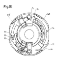
- these contact tracks which are flat rails, are embedded upright, so to speak, in the material of the B-end face 32 - here, however, other embodiments are also possible, as will be explained below with reference to FIG 16 is explained.
- FIG. 15 shows the same representation of FIG. 14 only with the carbon brush switching ring rotated, that the carbon brushes connected to the rotor via the collector have the rotor connections in the respective switch-over rotational end positions with reference to FIG maintain the polarization of the field winding, with a corresponding change in the direction of rotation and at the same time reposition the carbon brush contact areas on the collector, so that an equally good commutation can be achieved in both cases and therefore a similar efficiency can be achieved for both directions of rotation.
- the changeover contact rails 34a 'and 34b' which are embedded in or placed on the end face material of the B-end shield, each form two contact points or contact surfaces, each of which is shown in FIG. 11 with X and X 'or Y and Y 'are designated.
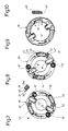
- FIGS. 7, 8 and 9 show the same view, in each case in the two end stops of the switching ring for switching between clockwise and counterclockwise rotation, while FIG. 9 shows the switching ring from the other side.
- This switching ring which is designated 35, then only carries the quiver 36 for the storage of the carbon brushes I ', II' with the corresponding bias springs 37 for the carbon brushes and is preferably made of a suitable stable, insulating material (plastic, as in also tie rod ring 24, the two end shields, a locking ring for the switching ring and possibly the fan 22). Since the contact points X, X '; Y, Y 'are formed for the electrical connection to the coals as lying in the plane of the end face 32 axial flat contacts, it is necessary that the switching ring on the correspondingly facing side forms corresponding axial flat contacts, which then axially in this plane over the entire surface rest on the contact surfaces formed by the changeover contact webs.
- the procedure is such that, in order to achieve the required contact pressure spring force for contacting, axial hollow projections are arranged on the side of the switching ring facing away from the rotor, which in the direction of the end face 32 and the contacts X, X ', Y supported thereon , Y 'of the B-end shield 12 are open - such a hollow projection is shown in section between the two FIGS. 7 and 8 above and designated 38. That this cut representation corresponding section is indicated in Fig. 8 with yy.
- a U-shaped contact bracket 39 is mounted under the bias of a spring 40 so that its contact surface 39a is biased by the spring 38 in the direction of the contact surfaces X, X ', Y, Y' of the changeover contact webs 34a ', 34b' 11, these axial contact surfaces of the changeover contact bars in this exemplary embodiment being obtained by bending the contact rail profiles embedded upright in the material of the B-bearing plate.
- the U-shaped contact bracket 39 penetrates the hollow projection 38 at a point opposite its contact surface 39a with a contact tongue 41, and the contact terminal 42, which is connected to the respective carbon brush according to FIG. 7, is then placed on this contact tongue.
- Such a wide-area axial contact ensures not only a perfect contact, but also a constant cleaning effect on the contact surfaces, since these rub against each other until the respective contact end position is reached under pressure.
- the respective end positions and an additional center-zero position for the contact changeover between clockwise and counter-clockwise rotation can finally be made latching by one or two, then preferably diametrically opposite, material tongues 47 of the switching ring 35; these material tongues are cut out circumferentially along partial circles on the inner circumference and have a projection 48 directed towards the end face 32 of the B-end shield, as shown in FIG. 10. With this nose-like projection 48 they snap into recesses 50, 50 ', 50 ⁇ , which run along corresponding partial circles in the end face 32 of the B-end shield, and thus position the two end positions for switching from right to left and the central position in the detent 50, in which the engine is then switched off at the same time. This results in the possibility of switching on and off of the motor at the same time as switching between clockwise and counterclockwise rotation.
- the switching ring 35 is pushed together with the assembly just described over the shoulder 12d of the B-bearing plate until it rests with its facing, resilient contacts 39a on the end face 32 of the B-bearing plate.
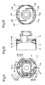
- a locking ring 51 (FIG. 12) is provided for fixing the switching ring, which preferably grips the outer ring edge of the switching ring 35 by an inwardly projecting ring flange 51a and holds it in place for carrying out the corresponding rotational movement, the locking ring 51 itself being best Axial projections 51b evenly distributed over the circumference, which are provided at their ends with locking lugs 52, engage in corresponding locking recesses 53 on the outer wall of the B-end shield 12.
- the construction of the universal motor is hereby completed, so that for the automatic production made possible from one level, only a total of seven sub-components are required, namely the left A-end shield in the drawing in FIG. 1, the stabilizing plate associated with its base, which is then used Pre-assembly unit consisting of the rotor shaft, rotor, fan and the two bearings, the air guide ring that also forms the tie rod, the right-hand B-bearing plate, the switching ring placed on its free outward-facing ring surface that carries the corresponding contact rails and webs, and the part pivoting on the switching ring B-bearing shield retaining ring.
- An alternative embodiment finally consists in the fact that with a full-surface support, as can be seen at 34b ', the fixing of such a semicircular flat rail can also be carried out without additional bends by leaving openings 55 at certain points in the flat rail material, to the resilient on both sides Adjacent webs 56.
- the opening 55 is then penetrated by a slightly larger diameter protruding from the end ring surface of the B-bearing plate, in the adjacent edge regions of which the sharp-edged front edges of the springs 56 then dig in, so that a pulling off of a then attached contact tape is excluded. It goes without saying that the attachment is carried out several times at suitable locations.
- these two types of fastening are also the Contact webs possible because these contact webs are also held, so to speak, by the axial contact through the attached switching ring.
- the type of contact made here thus includes a spring contact with a U-bracket including compression spring with explicit axial contacting and contacting in one plane by the pressing pressure developed by the spring.
- the carbon guides receiving the carbon brushes and the throttle cup can be injection molded directly onto the switching ring, the interposition of the throttles being possible by changing the plug and the contact leading to the throttle being guided as a contact web below the throttle cup, so that here too, the smallest space is required.
Landscapes
- Engineering & Computer Science (AREA)
- Power Engineering (AREA)
- Mechanical Engineering (AREA)
- Physics & Mathematics (AREA)
- Electromagnetism (AREA)
- Motor Or Generator Frames (AREA)
- Reciprocating, Oscillating Or Vibrating Motors (AREA)
- Lens Barrels (AREA)
- Dc Machiner (AREA)
- Valve Device For Special Equipments (AREA)
- Fittings On The Vehicle Exterior For Carrying Loads, And Devices For Holding Or Mounting Articles (AREA)
- Electrically Driven Valve-Operating Means (AREA)
Priority Applications (1)
| Application Number | Priority Date | Filing Date | Title |
|---|---|---|---|
| EP94103521A EP0608916B1 (fr) | 1989-07-15 | 1990-07-04 | Moteur électrique universel |
Applications Claiming Priority (2)
| Application Number | Priority Date | Filing Date | Title |
|---|---|---|---|
| DE3923421 | 1989-07-15 | ||
| DE3923421A DE3923421A1 (de) | 1989-07-15 | 1989-07-15 | Elektrischer universalmotor |
Related Child Applications (1)
| Application Number | Title | Priority Date | Filing Date |
|---|---|---|---|
| EP94103521.4 Division-Into | 1990-07-04 |
Publications (3)
| Publication Number | Publication Date |
|---|---|
| EP0408988A2 true EP0408988A2 (fr) | 1991-01-23 |
| EP0408988A3 EP0408988A3 (en) | 1992-08-19 |
| EP0408988B1 EP0408988B1 (fr) | 1994-12-14 |
Family
ID=6385099
Family Applications (2)
| Application Number | Title | Priority Date | Filing Date |
|---|---|---|---|
| EP90112749A Expired - Lifetime EP0408988B1 (fr) | 1989-07-15 | 1990-07-04 | Moteur électrique universel |
| EP94103521A Expired - Lifetime EP0608916B1 (fr) | 1989-07-15 | 1990-07-04 | Moteur électrique universel |
Family Applications After (1)
| Application Number | Title | Priority Date | Filing Date |
|---|---|---|---|
| EP94103521A Expired - Lifetime EP0608916B1 (fr) | 1989-07-15 | 1990-07-04 | Moteur électrique universel |
Country Status (5)
| Country | Link |
|---|---|
| US (1) | US5196747A (fr) |
| EP (2) | EP0408988B1 (fr) |
| JP (1) | JP2846425B2 (fr) |
| AT (2) | ATE115785T1 (fr) |
| DE (3) | DE3923421A1 (fr) |
Cited By (6)
| Publication number | Priority date | Publication date | Assignee | Title |
|---|---|---|---|---|
| ES2039143A1 (es) * | 1990-06-21 | 1993-08-16 | Bosch Gmbh Robert | Accionamiento por motor electrico. |
| EP0552378A4 (en) * | 1991-08-08 | 1994-08-10 | Fanuc Ltd | Stator/housing assembly of an electric motor |
| EP0612589A1 (fr) * | 1993-02-26 | 1994-08-31 | Kress-elektrik GmbH + Co. Elektromotorenfabrik | Dispositif de commande pour outils électriques |
| EP0544213B1 (fr) * | 1991-11-26 | 1997-04-23 | FHP Motors GmbH | Carcasse, en particulier pour petites machines électriques |
| GB2334630A (en) * | 1998-02-20 | 1999-08-25 | Scintilla Ag | Actuating member for rotatably displacing brush support in a power driven hand tool |
| US6664701B1 (en) | 2002-06-13 | 2003-12-16 | Black & Decker Inc. | Brush assembly |
Families Citing this family (56)
| Publication number | Priority date | Publication date | Assignee | Title |
|---|---|---|---|---|
| ATE116490T1 (de) * | 1989-07-15 | 1995-01-15 | Kress Elektrik Gmbh & Co | Elektrowerkzeug. |
| DE4004464A1 (de) * | 1989-07-15 | 1991-01-24 | Kress Elektrik Gmbh & Co | Elektrowerkzeug |
| DE4235649A1 (de) * | 1992-10-22 | 1994-04-28 | Egon Schmid | Gleichstrom-Elektromotor mit Permanenterregung |
| DE4336312C2 (de) * | 1993-10-25 | 2003-09-25 | Schlafhorst & Co W | Vorrichtung zum Wickeln von Garnkörpern |
| DE4412319A1 (de) * | 1994-04-11 | 1995-10-12 | Teves Gmbh Alfred | Stromzuführungsanordnung für einen Elektromotor mit vier Bürsten |
| US5744885A (en) * | 1994-12-16 | 1998-04-28 | General Electric Co. | Modular generator frame construction |
| DE19545651A1 (de) * | 1995-12-07 | 1997-06-12 | Marquardt Gmbh | Verstellvorrichtung für die Kohlebürsten an einem Elektromotor |
| US5952751A (en) * | 1996-01-23 | 1999-09-14 | Seiko Epson Corporation | Motor casing and method of producing same |
| US6011331A (en) * | 1997-04-22 | 2000-01-04 | Emerson Electric Co. | Electric motor having an improved airflow cooling system |
| EP0883228B1 (fr) * | 1997-06-03 | 2005-03-30 | Frankl & Kirchner GmbH. & Co. KG Fabrik für Elektromotoren und elektrische Apparate | Moteur électrique |
| DE19726016A1 (de) * | 1997-06-19 | 1998-12-24 | Teves Gmbh Alfred | Rotor für eine elektrische Maschine |
| US5955802A (en) * | 1997-12-19 | 1999-09-21 | Black & Decker Inc. | Reversing mechanism for electric motors |
| FR2776857B1 (fr) * | 1998-03-26 | 2000-06-16 | Meritor Light Vehicle Sys Ltd | Moteur electrique d'activation d'un organe fonctionnel de vehicule automobile |
| DE19839640B4 (de) * | 1998-08-31 | 2004-12-23 | Siemens Ag | Motor mit in einer Lageraufnahme mit Axialspieleinstellung für eine Rotorwelle fixierbarem Kalottenlager und Verfahren zur Axialspieleinstellung für eine Rotorwelle |
| FR2797921B1 (fr) * | 1999-09-01 | 2001-09-28 | Alstom | Nacelle d'eolienne constituee par la carcasse d'un generateur electrique |
| US6445097B1 (en) | 1999-12-01 | 2002-09-03 | Milwaukee Electric Tool Corporation | Method for assembling and electrical connector assembly for a power tool |
| US6400058B1 (en) * | 2000-08-01 | 2002-06-04 | Primax Electronics Ltd. | Universal motor with reduced EMI characteristics |
| DE10054697A1 (de) * | 2000-11-04 | 2002-05-08 | Schlafhorst & Co W | Auflösewalze für eine Offenend-Spinnvorrichtung |
| US6733414B2 (en) | 2001-01-12 | 2004-05-11 | Milwaukee Electric Tool Corporation | Gear assembly for a power tool |
| US6439855B1 (en) * | 2001-02-12 | 2002-08-27 | Siemens Automotive, Inc. | Direct current electric motor which eliminates outer case and places brushes and chokes in space efficient locations |
| GB0111535D0 (en) * | 2001-05-11 | 2001-07-04 | Johnson Electric Sa | Gear motor for power tool |
| US6525439B2 (en) * | 2001-07-30 | 2003-02-25 | Kelsey-Hayes Company | Electric motor end plate assembly with integrated motor driver transistor |
| DE10220793B4 (de) * | 2002-05-10 | 2007-04-12 | Hilti Ag | Drehverschwenkbarer Kommutatorschwenkschalter |
| DE10261025A1 (de) * | 2002-12-24 | 2004-07-08 | Robert Bosch Gmbh | Elektrowerkzeugmaschine mit mehreren, in getrennten Gehäusen untergebrachten Funktionsbaugruppen |
| US7063170B2 (en) * | 2003-02-26 | 2006-06-20 | Black & Decker Inc. | Flexible power tool motor pack and method of making the same |
| DE102004010402A1 (de) * | 2004-03-03 | 2005-09-22 | Siemens Ag | Gehäuseloser Elektromotor |
| DE102004030313B4 (de) * | 2004-06-23 | 2019-10-31 | Robert Bosch Gmbh | Handwerkzeugmaschine |
| TWI253800B (en) * | 2004-11-22 | 2006-04-21 | Univ Nat Cheng Kung | Direct-current brushless motor combined with planetary gear train |
| EP1750289A1 (fr) * | 2005-08-05 | 2007-02-07 | CEKA Elektrowerkzeuge AG + Co. KG | Dispositif de commutation |
| JP2007143314A (ja) * | 2005-11-18 | 2007-06-07 | Makita Corp | 電動工具の正逆切替装置 |
| JP2007143346A (ja) * | 2005-11-21 | 2007-06-07 | Makita Corp | 電動工具の正逆切替装置 |
| DE102006000161A1 (de) * | 2006-04-06 | 2007-10-11 | Hilti Ag | Kohlehaltervorrichtung |
| JP5026890B2 (ja) * | 2007-08-27 | 2012-09-19 | 株式会社マキタ | 電動工具の正逆切替装置 |
| DE102007057033A1 (de) * | 2007-11-27 | 2009-05-28 | Robert Bosch Gmbh | Elektrisch antreibbare Handwerkzeugmaschine |
| JP5019126B2 (ja) * | 2008-01-15 | 2012-09-05 | 日立工機株式会社 | 電動工具 |
| DE102008013402A1 (de) * | 2008-03-10 | 2009-09-17 | Robert Bosch Gmbh | Elektrische Maschine für ein Hybridfahrzeug sowie Lagerschild der elektrischen Maschine |
| GB0809764D0 (en) * | 2008-05-30 | 2008-07-09 | Johnson Electric Sa | Electric motor |
| CN102111037B (zh) * | 2009-12-29 | 2014-09-03 | 德昌电机(深圳)有限公司 | 电机 |
| DE102010000722A1 (de) * | 2010-01-07 | 2011-07-14 | Robert Bosch GmbH, 70469 | Handwerkzeugmaschinenvorrichtung |
| DE102011005593A1 (de) * | 2011-03-16 | 2012-09-20 | Hilti Aktiengesellschaft | Handwerkzeugmaschine |
| DE102011078082B4 (de) * | 2011-06-27 | 2022-08-11 | Robert Bosch Gmbh | Handwerkzeugmaschine, insbesondere Bohr- oder Schraubgerät |
| DE102012014453A1 (de) * | 2012-07-21 | 2014-01-23 | Audi Ag | Elektrische Maschine und Kraftfahrzeug mit einer derartigen elektrischen Maschine |
| FR3003412B1 (fr) * | 2013-03-14 | 2016-12-09 | Valeo Equip Electr Moteur | Rotor de machine electrique muni d'au moins une frette de maintien des chignons du bobinage et machine electrique correspondante |
| CN104668657A (zh) * | 2013-12-02 | 2015-06-03 | 苏州宝时得电动工具有限公司 | 一种手持切割机 |
| CN204030811U (zh) * | 2014-06-23 | 2014-12-17 | 德昌电机(深圳)有限公司 | 一种电刷装置及使用该电刷装置的有刷电机 |
| JP6374449B2 (ja) * | 2016-07-25 | 2018-08-15 | ファナック株式会社 | ステータおよび電動機 |
| CN107542963B (zh) * | 2017-09-29 | 2019-04-23 | 上海超诚科技发展有限公司 | 一种机械式短时响应的电磁阀组件控制装置 |
| EP3765226B1 (fr) | 2018-03-16 | 2023-11-01 | Milwaukee Electric Tool Corporation | Serre-lame pour outil électrique, outil électrique alternatif et procédé d'utilisation d'un tel serre-lame |
| WO2019194987A1 (fr) | 2018-04-03 | 2019-10-10 | Milwaukee Electric Tool Corporation | Scie sauteuse |
| USD887806S1 (en) | 2018-04-03 | 2020-06-23 | Milwaukee Electric Tool Corporation | Jigsaw |
| DE102018118275A1 (de) * | 2018-07-27 | 2020-01-30 | Valeo Siemens Eautomotive Germany Gmbh | Rotoranordnung für eine elektrische Maschine, elektrische Maschine für ein Fahrzeug und Fahrzeug |
| WO2021044799A1 (fr) | 2019-09-06 | 2021-03-11 | 株式会社マキタ | Outil électrique |
| CN113245621B (zh) * | 2020-02-11 | 2023-04-07 | 南京泉峰科技有限公司 | 往复锯 |
| DE102020130556B4 (de) | 2020-11-19 | 2023-01-05 | Schaeffler Technologies AG & Co. KG | Elektrische Maschine |
| JP7840138B2 (ja) * | 2021-11-17 | 2026-04-03 | 株式会社マキタ | 電動工具 |
| DE102024003599B4 (de) | 2024-10-31 | 2026-08-13 | Mercedes-Benz Group AG | Antriebseinheit für ein Kraftfahrzeug sowie Kraftfahrzeug |
Family Cites Families (26)
| Publication number | Priority date | Publication date | Assignee | Title |
|---|---|---|---|---|
| US2817827A (en) * | 1952-02-28 | 1957-12-24 | Millers Falls Co | Electrical connector |
| CA579613A (fr) * | 1955-10-04 | 1959-07-14 | G. Potter Marion | Moteur submersible |
| US3369136A (en) * | 1965-08-06 | 1968-02-13 | Smith Corp A O | Submersible motor |
| US3440465A (en) * | 1965-10-01 | 1969-04-22 | Millers Falls Co | Reversing mechanism for electric motors |
| US3462623A (en) * | 1968-04-16 | 1969-08-19 | Singer Co | Double insulated power tools |
| US3610975A (en) * | 1969-07-30 | 1971-10-05 | Westinghouse Electric Corp | Dynamoelectric machine with improved cooling means |
| US3703646A (en) * | 1970-12-11 | 1972-11-21 | Murphy Ind Inc G W | Electric tool with trigger switch and lock-out arrangement |
| DE2101007A1 (de) * | 1971-01-11 | 1972-09-07 | Glider E | Ständer einer elektrischen Maschine |
| DE2101077A1 (en) * | 1971-01-12 | 1972-08-03 | Robert Harvey Schmidt Enterprises, Inc., Indianapolis, Ind. (V.St.A.) | Cooling mixture - contg urea, ammonium nitrate and water or alcohol |
| US3699366A (en) * | 1971-06-07 | 1972-10-17 | Black & Decker Mfg Co | Power tool with motor support means |
| US3829721A (en) * | 1973-07-30 | 1974-08-13 | Black & Decker Mfg Co | Air flow baffle construction for electric motor devices |
| DE2831928A1 (de) * | 1978-07-20 | 1980-03-20 | Bosch Gmbh Robert | Buerstenhalter fuer kleine kommutator-motoren, insbesondere fuer heimwerker-kombinationsmaschinen |
| DE3149106A1 (de) * | 1981-12-11 | 1983-06-23 | Robert Bosch Gmbh, 7000 Stuttgart | Elektrische kleinmaschine, insbesondere kleinmotor |
| DE3235622A1 (de) * | 1982-09-25 | 1984-03-29 | SWF-Spezialfabrik für Autozubehör Gustav Rau GmbH, 7120 Bietigheim-Bissingen | Elektrischer kleinmotor, insbesondere fuer scheibenwischanlagen in kraftfahrzeugen |
| US4523116A (en) * | 1983-03-31 | 1985-06-11 | Black & Decker, Inc. | Electrical connection system for motors |
| DE3466916D1 (en) * | 1983-09-09 | 1987-11-26 | Black & Decker Inc | Components for electric motors |
| US4593220A (en) * | 1984-07-12 | 1986-06-03 | Black & Decker Inc. | Brush bearing sub-assembly for electric motor |
| DE3604675A1 (de) * | 1985-04-12 | 1987-08-20 | Licentia Gmbh | Antriebsmotor fuer ein geraet |
| DE3524614A1 (de) * | 1985-07-10 | 1987-01-15 | Bosch Gmbh Robert | Handwerkzeugmaschine fuer rechts- und linkslauf |
| GB8526834D0 (en) * | 1985-10-31 | 1985-12-04 | Black & Decker Inc | Electric motors & components |
| DE3538939A1 (de) * | 1985-10-31 | 1987-05-07 | Black & Decker Inc | Becherfoermige lagerbruecke |
| DE3538940A1 (de) * | 1985-10-31 | 1987-05-07 | Black & Decker Inc | Verdrahtungsanordnung fuer den motor eines elektrowerkzeugs |
| GB2186342A (en) * | 1986-02-06 | 1987-08-12 | Johnson Electric Ind Mfg | An electric motor and gearbox unit and component parts thereof |
| EP0306795B1 (fr) * | 1987-09-11 | 1991-11-27 | Siemens Aktiengesellschaft | Dispositif d'entraînement électromoteur pour la manoeuvre de fenêtres, de toits ouvrants ou d'objets semblables, notamment pour véhicules automobiles |
| DE3731079A1 (de) * | 1987-09-16 | 1989-03-30 | Metabowerke Kg | Elektrohandwerkzeug mit einem universalmotor mit rechts- und linkslauf |
| NL8800366A (nl) * | 1988-02-15 | 1989-09-01 | Emerson Electric Co | Montage-inrichting voor borstels bij een omkeerbare collectormotor. |
-
1989
- 1989-07-15 DE DE3923421A patent/DE3923421A1/de active Granted
-
1990
- 1990-07-04 EP EP90112749A patent/EP0408988B1/fr not_active Expired - Lifetime
- 1990-07-04 AT AT90112749T patent/ATE115785T1/de not_active IP Right Cessation
- 1990-07-04 DE DE59007988T patent/DE59007988D1/de not_active Expired - Fee Related
- 1990-07-04 EP EP94103521A patent/EP0608916B1/fr not_active Expired - Lifetime
- 1990-07-04 AT AT94103521T patent/ATE160059T1/de not_active IP Right Cessation
- 1990-07-04 DE DE59010772T patent/DE59010772D1/de not_active Expired - Fee Related
- 1990-07-11 US US07/551,510 patent/US5196747A/en not_active Expired - Lifetime
- 1990-07-16 JP JP2185440A patent/JP2846425B2/ja not_active Expired - Fee Related
Cited By (7)
| Publication number | Priority date | Publication date | Assignee | Title |
|---|---|---|---|---|
| ES2039143A1 (es) * | 1990-06-21 | 1993-08-16 | Bosch Gmbh Robert | Accionamiento por motor electrico. |
| EP0552378A4 (en) * | 1991-08-08 | 1994-08-10 | Fanuc Ltd | Stator/housing assembly of an electric motor |
| EP0544213B1 (fr) * | 1991-11-26 | 1997-04-23 | FHP Motors GmbH | Carcasse, en particulier pour petites machines électriques |
| EP0612589A1 (fr) * | 1993-02-26 | 1994-08-31 | Kress-elektrik GmbH + Co. Elektromotorenfabrik | Dispositif de commande pour outils électriques |
| GB2334630A (en) * | 1998-02-20 | 1999-08-25 | Scintilla Ag | Actuating member for rotatably displacing brush support in a power driven hand tool |
| GB2334630B (en) * | 1998-02-20 | 2000-05-31 | Scintilla Ag | Power-driven hand tool |
| US6664701B1 (en) | 2002-06-13 | 2003-12-16 | Black & Decker Inc. | Brush assembly |
Also Published As
| Publication number | Publication date |
|---|---|
| JPH03139152A (ja) | 1991-06-13 |
| DE3923421C2 (fr) | 1992-11-26 |
| EP0608916B1 (fr) | 1997-11-05 |
| EP0608916A2 (fr) | 1994-08-03 |
| US5196747A (en) | 1993-03-23 |
| EP0408988B1 (fr) | 1994-12-14 |
| DE59007988D1 (de) | 1995-01-26 |
| EP0608916A3 (fr) | 1996-04-17 |
| JP2846425B2 (ja) | 1999-01-13 |
| EP0408988A3 (en) | 1992-08-19 |
| DE59010772D1 (de) | 1997-12-11 |
| ATE160059T1 (de) | 1997-11-15 |
| ATE115785T1 (de) | 1994-12-15 |
| DE3923421A1 (de) | 1991-01-24 |
Similar Documents
| Publication | Publication Date | Title |
|---|---|---|
| EP0608916B1 (fr) | Moteur électrique universel | |
| EP0322832B1 (fr) | Moteur électrique universel | |
| DE3912873C2 (fr) | ||
| DE3312686C2 (fr) | ||
| DE3404974C2 (de) | Elektromotor | |
| DE3607552A1 (de) | Elektromotorstator | |
| DE102005001705A1 (de) | Verfahren zur Herstellung von Ankern, Verfahren zur Herstellung von Elektromotoren sowie Anker | |
| DE69002535T2 (de) | Bürstenhalter für einen Elektromotor. | |
| DE102013003024A1 (de) | Elektromotor, insbesondere einer Fahrzeugkomponente | |
| EP3078099B1 (fr) | Stator pour moteur à courant continu à commutation électronique | |
| DE29516656U1 (de) | Kollektorloser Elektromotor | |
| EP0615331B1 (fr) | Moteur série ou universel muni d'un dispositif de freinage | |
| DE69209710T2 (de) | Befestigungsvorrichtung einer Drosselspule für Kleinstmotoren | |
| DE102004050374B4 (de) | Elektrische Maschine, insbesondere Gleichstrommotor | |
| EP0225978A2 (fr) | Dispositif à balais pour moteurs électriques | |
| DE8908646U1 (de) | Elektrischer Universalmotor | |
| DE3943651C2 (fr) | ||
| EP2377229A2 (fr) | Stator dans un moteur électrique | |
| DE60319199T2 (de) | Kernloser Motor | |
| DE3502442A1 (de) | Elektromotor | |
| EP1001509A2 (fr) | Moteur à commutateur antiparasité, notamment servomoteur avec réglage de vitesse pour véhicules à moteur | |
| DD248682A1 (de) | Anordnung zur herstellung von elektrischen verbindungen in einem elektromotor | |
| EP0108434B1 (fr) | Moteur électrique | |
| EP1601080A1 (fr) | Moteur electrique sans balais | |
| WO1999056377A2 (fr) | Enroulement d'induit pour moteur a collecteur |
Legal Events
| Date | Code | Title | Description |
|---|---|---|---|
| PUAI | Public reference made under article 153(3) epc to a published international application that has entered the european phase |
Free format text: ORIGINAL CODE: 0009012 |
|
| AK | Designated contracting states |
Kind code of ref document: A2 Designated state(s): AT BE CH DE DK ES FR GB GR IT LI LU NL SE |
|
| PUAL | Search report despatched |
Free format text: ORIGINAL CODE: 0009013 |
|
| AK | Designated contracting states |
Kind code of ref document: A3 Designated state(s): AT BE CH DE DK ES FR GB GR IT LI LU NL SE |
|
| 17P | Request for examination filed |
Effective date: 19921120 |
|
| 17Q | First examination report despatched |
Effective date: 19930804 |
|
| GRAA | (expected) grant |
Free format text: ORIGINAL CODE: 0009210 |
|
| AK | Designated contracting states |
Kind code of ref document: B1 Designated state(s): AT BE CH DE DK ES FR GB GR IT LI LU NL SE |
|
| PG25 | Lapsed in a contracting state [announced via postgrant information from national office to epo] |
Ref country code: DK Effective date: 19941214 Ref country code: GR Free format text: LAPSE BECAUSE OF FAILURE TO SUBMIT A TRANSLATION OF THE DESCRIPTION OR TO PAY THE FEE WITHIN THE PRESCRIBED TIME-LIMIT Effective date: 19941214 Ref country code: ES Free format text: THE PATENT HAS BEEN ANNULLED BY A DECISION OF A NATIONAL AUTHORITY Effective date: 19941214 Ref country code: NL Effective date: 19941214 Ref country code: BE Effective date: 19941214 |
|
| REF | Corresponds to: |
Ref document number: 115785 Country of ref document: AT Date of ref document: 19941215 Kind code of ref document: T |
|
| REF | Corresponds to: |
Ref document number: 59007988 Country of ref document: DE Date of ref document: 19950126 |
|
| ITF | It: translation for a ep patent filed | ||
| PG25 | Lapsed in a contracting state [announced via postgrant information from national office to epo] |
Ref country code: SE Effective date: 19950314 |
|
| ET | Fr: translation filed | ||
| GBT | Gb: translation of ep patent filed (gb section 77(6)(a)/1977) |
Effective date: 19950303 |
|
| NLV1 | Nl: lapsed or annulled due to failure to fulfill the requirements of art. 29p and 29m of the patents act | ||
| PG25 | Lapsed in a contracting state [announced via postgrant information from national office to epo] |
Ref country code: LU Free format text: LAPSE BECAUSE OF NON-PAYMENT OF DUE FEES Effective date: 19950731 |
|
| PLBE | No opposition filed within time limit |
Free format text: ORIGINAL CODE: 0009261 |
|
| STAA | Information on the status of an ep patent application or granted ep patent |
Free format text: STATUS: NO OPPOSITION FILED WITHIN TIME LIMIT |
|
| 26N | No opposition filed | ||
| PGFP | Annual fee paid to national office [announced via postgrant information from national office to epo] |
Ref country code: GB Payment date: 20010612 Year of fee payment: 12 |
|
| PGFP | Annual fee paid to national office [announced via postgrant information from national office to epo] |
Ref country code: CH Payment date: 20010723 Year of fee payment: 12 |
|
| PGFP | Annual fee paid to national office [announced via postgrant information from national office to epo] |
Ref country code: AT Payment date: 20010730 Year of fee payment: 12 |
|
| REG | Reference to a national code |
Ref country code: GB Ref legal event code: IF02 |
|
| PG25 | Lapsed in a contracting state [announced via postgrant information from national office to epo] |
Ref country code: AT Free format text: LAPSE BECAUSE OF NON-PAYMENT OF DUE FEES Effective date: 20020704 Ref country code: GB Free format text: LAPSE BECAUSE OF NON-PAYMENT OF DUE FEES Effective date: 20020704 |
|
| PG25 | Lapsed in a contracting state [announced via postgrant information from national office to epo] |
Ref country code: CH Free format text: LAPSE BECAUSE OF NON-PAYMENT OF DUE FEES Effective date: 20020731 Ref country code: LI Free format text: LAPSE BECAUSE OF NON-PAYMENT OF DUE FEES Effective date: 20020731 |
|
| GBPC | Gb: european patent ceased through non-payment of renewal fee |
Effective date: 20020704 |
|
| REG | Reference to a national code |
Ref country code: CH Ref legal event code: PL |
|
| PG25 | Lapsed in a contracting state [announced via postgrant information from national office to epo] |
Ref country code: IT Free format text: LAPSE BECAUSE OF NON-PAYMENT OF DUE FEES;WARNING: LAPSES OF ITALIAN PATENTS WITH EFFECTIVE DATE BEFORE 2007 MAY HAVE OCCURRED AT ANY TIME BEFORE 2007. THE CORRECT EFFECTIVE DATE MAY BE DIFFERENT FROM THE ONE RECORDED. Effective date: 20050704 |
|
| PGFP | Annual fee paid to national office [announced via postgrant information from national office to epo] |
Ref country code: DE Payment date: 20080731 Year of fee payment: 19 |
|
| PGFP | Annual fee paid to national office [announced via postgrant information from national office to epo] |
Ref country code: FR Payment date: 20080718 Year of fee payment: 19 |
|
| REG | Reference to a national code |
Ref country code: FR Ref legal event code: ST Effective date: 20100331 |
|
| PG25 | Lapsed in a contracting state [announced via postgrant information from national office to epo] |
Ref country code: FR Free format text: LAPSE BECAUSE OF NON-PAYMENT OF DUE FEES Effective date: 20090731 |
|
| PG25 | Lapsed in a contracting state [announced via postgrant information from national office to epo] |
Ref country code: DE Free format text: LAPSE BECAUSE OF NON-PAYMENT OF DUE FEES Effective date: 20100202 |