EP0408996A2 - Dispositif de tirage de films tubulaires en matière plastique - Google Patents
Dispositif de tirage de films tubulaires en matière plastique Download PDFInfo
- Publication number
- EP0408996A2 EP0408996A2 EP90112818A EP90112818A EP0408996A2 EP 0408996 A2 EP0408996 A2 EP 0408996A2 EP 90112818 A EP90112818 A EP 90112818A EP 90112818 A EP90112818 A EP 90112818A EP 0408996 A2 EP0408996 A2 EP 0408996A2
- Authority
- EP
- European Patent Office
- Prior art keywords
- slewing ring
- turning bar
- slewing
- turntable
- turning
- Prior art date
- Legal status (The legal status is an assumption and is not a legal conclusion. Google has not performed a legal analysis and makes no representation as to the accuracy of the status listed.)
- Granted
Links
- 239000002985 plastic film Substances 0.000 claims abstract description 9
- 229920006255 plastic film Polymers 0.000 claims abstract description 9
- 238000004804 winding Methods 0.000 claims abstract description 9
- 238000005096 rolling process Methods 0.000 claims abstract description 5
- 230000001105 regulatory effect Effects 0.000 claims description 2
- 230000002093 peripheral effect Effects 0.000 claims 2
- 230000003247 decreasing effect Effects 0.000 claims 1
- 230000002452 interceptive effect Effects 0.000 claims 1
- 238000000034 method Methods 0.000 description 7
- 238000001125 extrusion Methods 0.000 description 5
- 238000006073 displacement reaction Methods 0.000 description 3
- 238000000605 extraction Methods 0.000 description 3
- 238000012423 maintenance Methods 0.000 description 3
- 238000004519 manufacturing process Methods 0.000 description 3
- 239000011324 bead Substances 0.000 description 2
- 230000015572 biosynthetic process Effects 0.000 description 2
- 238000001816 cooling Methods 0.000 description 2
- 230000007423 decrease Effects 0.000 description 2
- 238000010096 film blowing Methods 0.000 description 2
- 238000003780 insertion Methods 0.000 description 2
- 230000037431 insertion Effects 0.000 description 2
- 230000033228 biological regulation Effects 0.000 description 1
- 230000005540 biological transmission Effects 0.000 description 1
- 238000007664 blowing Methods 0.000 description 1
- 230000001419 dependent effect Effects 0.000 description 1
- 238000013461 design Methods 0.000 description 1
- 238000009826 distribution Methods 0.000 description 1
- 230000000694 effects Effects 0.000 description 1
- 238000012544 monitoring process Methods 0.000 description 1
- 239000000256 polyoxyethylene sorbitan monolaurate Substances 0.000 description 1
- 238000012545 processing Methods 0.000 description 1
Images





Classifications
-
- B—PERFORMING OPERATIONS; TRANSPORTING
- B29—WORKING OF PLASTICS; WORKING OF SUBSTANCES IN A PLASTIC STATE IN GENERAL
- B29C—SHAPING OR JOINING OF PLASTICS; SHAPING OF MATERIAL IN A PLASTIC STATE, NOT OTHERWISE PROVIDED FOR; AFTER-TREATMENT OF THE SHAPED PRODUCTS, e.g. REPAIRING
- B29C53/00—Shaping by bending, folding, twisting, straightening or flattening; Apparatus therefor
- B29C53/02—Bending or folding
- B29C53/10—Bending or folding of blown tubular films, e.g. gusseting
Definitions
- the invention relates to a take-off device for tubular webs made of plastic film produced by an extruder with a fixedly arranged blow head according to the preamble of patent claim 1.
- Thickness tolerances cannot be avoided when producing tubular webs from plastic film using the blowing process. These arise e.g. due to the usual manufacturing tolerances in the die head of the extruder used for film production, in the calibration device passed through by the tubular web with a widened round cross-section following the extrusion process, by the internal and external cooling or by other external circumstances.
- annular beads would form on the film wrap, which would result in permanent deformation of the film in this area and would make printing and further processing of the film tubular web difficult.
- the pivoting about the axis of the supplied tube track of the deflecting rollers and the turning bars in the device is made in such a way that the axes of the deflecting rollers and the turning bars are tangent to circles around the axis of rotation of the flat laying device, the deflecting rollers in every possible operating position are located radially outside the parts of the turning bars which are wrapped in the tubular track.
- the pivoting angle of the deflecting rollers and the turning bars decrease with increasing distance from the lay-flat device, and the film tube is between the deflecting rollers and turning bars and the stationary conveying device for transporting the flattened tubular web into one another parallel, horizontal planes.
- the lay-flat device, the deflecting rollers and the turning bars are all supported on a relatively thin central shaft for executing their reversing pivoting movements, which runs in the vertical extension of the axis of the supplied tubular web and is rotatably mounted in the device frame.
- the entire weight of the reversing system is borne by the medium shaft, with the result that the reversing system is very susceptible to fluctuations and pendulum movements, which occur very quickly, especially when the trigger device is appropriately high due to a long vertical trigger travel for example, an operator moves on the associated catwalk of the trigger device.
- the invention is therefore based on the object of creating a take-off device of the generic type while maintaining the kinematics of the reversing system and the controlled guidance of the tubular web thereby achieved from a stationary tubular film blowing head through the reversing take-off device to a, in turn, stationary winding device, in which the reversing system has a has improved stability which avoids disturbing fluctuations and pendulum movements, and at the same time the assembly and maintenance of the system and the introduction of the tubular web are facilitated.
- the reversibly pivoted parts of the device are supported on turntables, the inner diameter of which is at least equal to the maximum working width of the device, which corresponds to the largest possible track width of the flattened tubular web that can be handled in the device, i.e. the inner diameter of the slewing rings is approximately equal to the length of the deflecting rollers.
- the slewing ring assembly formed by the individual slewing rings represents a stable structure in which the slewing rings are only supported on one another by the roller bodies placed in between, and in terms of the bearing force, the slewing ring assembly is designed as an axial bearing.
- This design virtually eliminates disturbing fluctuations or pendulum movements when walking on a walkway or work platform attached to the device frame. Because of their large inner diameter, which is preferably the same for all slewing rings, the middle area of the reversing system of the extraction device, to which the vertically raised hose path runs into the system, is also kept free of such device parts that complicate assembly and maintenance or the insertion of the hose path at the beginning of a could hinder the extrusion process or make it cumbersome.
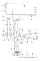
- a tubular web 1 made of plastic film is fed from an extruder with a fixedly arranged film blowing head (not shown) with a widened round or circular cross-section to a pull-off device, designated as a whole by 2, via which the expanded tubular web 1 is drawn flat and fed to a winding device (not shown) is, in which the flat tube sheet is wound into a supply roll.
- the tubular web 1 is in the vertical direction from the extruder die over a longer distance, as required for cooling and solidifying the plastic film, led up to the extraction device 2, which is accordingly usually arranged in the ceiling area of a corresponding manufacturing hall.
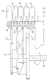
- the trigger device 2 comprises a device frame 3 which is supported on the hall floor by four vertical supports 4, 5, 6 and 7.
- the supports 4 to 7 carry an upper horizontal support part 8, on the inner end regions facing the tubular web 1 of which a supporting frame 9 for a rotating assembly 10 is supported on the upper side.
- the slewing ring assembly 10 is composed of individual slewing rings 11, 12, 13 and 14 which are arranged vertically one above the other and which have the same inside and outside diameters, their inside diameter also being aligned with the inside diameter of the holding frame 9.
- the slewing rings 11, 12, 13 and 14 are supported directly on top of one another or on the holding frame 9 via interposed rolling elements 15, in the example shown balls, and thus form an axial bearing which is subjected to pressure.
- the slewing rings 11 to 14 rest freely rotatable on each other and can be rotated relative to each other.
- the rolling elements or balls 15 are guided in tight grooves 16, which are incorporated in the opposing end faces of the slewing rings 11 to 14 or the holding frame 9, so that undesired transverse movements of the individual slewing rings in the slewing ring assembly 10 in horizontal planes are practically excluded are.
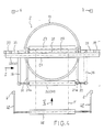
- the slewing rings 11 to 14 can be driven at different speeds via a separate motor assigned to each slewing ring or via a reversing gear 17, as shown in FIG. 3.
- the slewing rings 11 to 14 are provided on their outer circumference with a driving device 18, in the example shown in the form of an external toothing formed around the outer circumference of the slewing rings, for their drive connection with the reversing gear 17, which is located laterally outside the slewing ring package 10 on the device frame 3 in is not shown in more detail attached.
- the reversing gear 17 has a suitable one Motor (not shown) reversibly drivable drive shaft 19 which is aligned parallel to the vertical axis 20 of the slewing ring assembly 10.
- drive wheels 21, in the example shown gears are fixed on the drive shaft 19, each of which is held in drive connection with the identical driving device or external toothing 18 of the associated turntable 11 to 14 via intermediate wheels 22.
- the respective turntables 11 to 14 receive the appropriate reduction for their correspondingly provided rotational speed via the intermediate wheels 22, which ensure an equal distance between the drive shaft 19 and the axis 20 of the turntable package 10 in each drive transmission plane.
- a holding frame 23 is attached to the inner circumference of the lowermost turntable 11 and comprises two diametrically opposite circumferential parts 24, each with a vertical support leg 25.
- a flat laying device 26 with two squeezing rollers 27 rotatable about horizontal axes and two flat laying plates 28 converging towards them is attached to the mutually opposite supporting legs 25. The assembly of the flat laying device 26 is carried out on the area of the vertical support legs 25 which is led out downward from the slewing ring package 10.
- a guide roller 29 is freely rotatably mounted within the cylindrical inner sleeve plane of the turntable assembly 10, which is arranged essentially vertically above the roller gap defined by the squeezing rollers 27 at such a height that the tubular web 1 ', without touching the upper edge of the uppermost turntable 14, runs to a first, lower deflection roller 30.
- its upper culminating surface line lies above the horizontal plane occupied by the upper side of the uppermost turntable 14, which at the same time directly adjoins the horizontal plane occupied by the first, lower deflecting roller 30 with its lower culminating surface line.
- the deflecting roller 30 is rotatably mounted on the free ends of support arms 31 which extend from the upper end region of the respective vertical Support leg 25 of the holding frame 23 go out.
- the turntable 11 is driven by the reversing gear 17 at a rotational speed which corresponds to a reversing pivoting movement of 360 °, that is to say +/- 180 °, starting from a central position of the flat laying device 26.
- the reversing gear 17 can be reversed at the end of the respective swiveling part of the rotating ring 11 by means of suitable limit switches.
- a first turning bar 32 which can be designed in a known manner as a so-called air turning bar, which is provided for deflecting the tubular web with an air nozzle row.
- the turning bar 32 is non-rotatably attached to holding rails 33 which are fastened at diametrically opposite points on the outer circumference of the uppermost turntable 14 and fix the turning bar 32 in a non-rotatable manner between their outer ends 34.
- the turntable 14 receives a rotational speed from the reversing gear 17 for a pivoting angle of its turning bar 32 of 270 °.
- a second, upper deflection roller 35 is fastened to the outer circumference of the turntable 13 by means of holding rails 36.
- the holding rails 36 are in turn fastened at diametrically opposite locations on the outer circumference of the rotating ring 13, and the deflection roller 35 is freely rotatably mounted between their outwardly directed, opposite ends 37.
- the turntable 13 receives a rotational speed from the reversing gear 17 for a reversing pivoting angle of its deflection roller 35 about the vertical axis 20 of the turntable package 10 of 180 °.
- a turning bar 38 following the deflecting roller 35 which like the turning bar 32 can be designed as an air turning bar, is diametrically opposite one another on the outer circumference of the slewing ring 12 fastened holding rails 39 are supported on the slewing ring 12, their end faces being non-rotatably fixed between the outer ends 40 of the holding rails 39.
- the turntable 12 receives a rotational speed from the reversing gear 17 for a reversing pivoting movement of the turning bar 38 of 90 °.
- a deflecting roller 41 is supported on the device frame 3 in a freely rotatable manner as a stationary conveying device for removing the laid-flat tubular web 1.
- the vertical supports 4 and 5 of the device frame 1 are provided with horizontal upper support arms 42, between the free ends of which the deflection roller 41 is rotatably mounted.
- the deflecting rollers 30 and 35 and the turning bars 32 and 38 are held by their respective holding rails 31, 33, 36 and 39 in an area above and outside the slewing ring package 10.
- the outer end regions 31a, 34, 37 and 40 of the holding rails 31, 33, 36 and 39 of the deflecting rollers and turning bars or the deflecting rollers 30, 35 and the turning bars 32, 38 themselves define in their reversing pivoting movement about the axis 20 of the slewing ring package 10 different rotational speeds corresponding to the perturbation or limit circles with different radius as the distance from the squeeze rollers 27 decreases.
- the interference circle described by the slewing ring 11 with its deflection roller 30 is the smallest and surrounded by the interference circle of the slewing ring 14 with the turning bar 32.
- the next largest interference circle is that of the slewing ring 13 with the deflecting roller 35, and the interference circle of the slewing ring 12 with the upper turning bar 38 is the largest interference circle which surrounds all other interference circles. In the reversing operation of the take-off device, this ensures a mutually interference-free pivoting movement of the deflection rollers 30, 35 and the turning bars 32, 38, taking into account their different pivoting angles or different speeds of rotation.
- the outer rails 33, 36 and 39 are those around On the inside of the lower slewing ring 11 with simple straight holding rails 31, deflection roller 30, which is guided around the interference circles, is provided with horizontal rail parts 43 or 44 and 45 in order to shift the corresponding interference circles outwards accordingly, as can be seen in particular in FIG. 2.
- Fig. 2 shows with particular clarity that the deflecting roller 30, the turning bar 32, the deflecting roller 35 and the turning bar 38 are arranged one above the other in different horizontal planes in such a way that their opposite surface lines are each in a common horizontal plane.
- the rails 33, 36 and 39 of the slewing rings 14, 13 and 12 include vertical rail parts 46, 47 and 48 of appropriate height, as illustrated in FIG. 2.
- the roller gap defined by the two squeeze rollers 27 of the flat laying device 26 is, as can be seen in particular in FIG. 1, centered on the axis of rotation 20 of the slewing ring package 10, which in turn is arranged in an extension of the central axis 47 of the tubular web 1 running towards the squeeze rollers 27.
- one of the two squeeze rollers 27 is mounted in a fixed position, while the other is pivotably supported on the support legs 25. This pivoting is necessary for the pulling in of the tubular web 1 at the beginning of an extrusion process.
- the permanently mounted squeeze roller 27 can be driven by a speed-controllable motor (not shown).
- the turning bars 32 and 38 have a basic position running at a distance a from the axis of rotation 20 of the rotating assembly 10. This distance a corresponds to the radius of a circle circumscribed by the pivot path of the axes of the turning bars 32 and 38 in the reversing mode about the axis of rotation 20 and is calculated according to the formula turning bar diameter x ⁇ / 4. A pivoting of the turning bars 32 and 38 to pull in the tubular web 1 at the start of an extrusion process is in the this configuration is not necessary since there is unlimited freedom of work above the slewing ring package 10.
- the tube web 1 'laid flat between the squeeze rollers 27' is passed through the device 2 in accordance with the dash-dotted lines drawn in FIG. 1 and in FIGS. 4 to 10.
- the flattened tubular web 1 ' is initially fed with its axis in the axis of rotation 20 of the slewing ring package 10 guide roller 29 substantially in the vertical direction to be guided over it over this to the deflection roller 30 with a slight looping.
- the tubular web 1 runs around the inside of the turning bar 38 and is fed from the top of the same level stationary deflection roller 41, from which it is fed vertically downwards according to the arrow 49 in Fig. 1 of a stationary winding device.
- the tubular web 1 ' is guided between the deflecting rollers 30, 35 and the turning bars 32, 38 alternately outwards and inwards, towards the axis of rotation 20 of the slewing ring package 10, while at the same time the thickness tolerances of the plastic film according to the reversed pivoted parts of the pull-off device known principle of the reversing trigger devices can be distributed evenly over the hose.
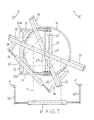
- FIG. 4 shows a middle position of the flat laying device 26 with its squeezing rollers 27, from which it can be seen that in this position the deflecting rollers 30 and 35 on the one hand and the turning bars 32 and 38 are aligned with one another in the direction of the axis of rotation 20 of the slewing ring package 10.
- 5 and 6 and 7 and 8 illustrate intermediate positions of the deflecting rollers 30, 35 and the turning bars 32, 38 corresponding to a swivel angle of 90 ° and 180 °, respectively, of the lay-flat device 26 with the squeezing rollers 27, starting from the central position according to FIG. 4 in both clockwise directions.
- the turning bars 32 and 38 can be adjusted in order to correct the tubular web course if necessary.
- the values determined by the side edge monitoring unit are forwarded to a control unit and evaluated.
- An actuator can be controlled via the control unit, which makes a corresponding adjustment.
- an adjustment of the upper turning bar 38 is sufficient to counteract a lateral course of the tubular web 1 'which may occur for whatever reason.
- the distance dimension a which the turning bar 38 maintains in its basic position from the axis of rotation 20 of the rotating assembly 10, can be changed.
- the change in the distance dimension a can take place, for example, in that the turning bar 38 is moved in the radial direction to the slewing ring assembly 10. This is illustrated in FIG. 9, which is a simplified illustration of the extraction device in an operating position according to FIG. 7.
- the tube 1' If the dimension a is reduced, as shown at 38 ', the tube 1', seen in the direction of travel 50, continues to the left, while conversely with an increase in dimension a, the tube 1 'continues to the right.
- the turning bar 38 is supported in an adjustable manner on the slewing ring 12 in a manner not shown.
- FIG. 10 illustrates a representation corresponding to FIG. 9 according to another embodiment of the adjustment of the turning bar 38 for influencing the hose path.
- the turning bar 38 is supported on the associated turntable 12 so as to be pivotable about a vertical axis, this pivoting movement of the turning bar 38 being the reversing one Pivoting movement of the slewing ring 12 can be superimposed in a suitable manner.
- the turning bar 38 is at an angle of 30 ° at a given point in time during its pivoting movement, it can be pivoted by corresponding control pulses in accordance with the double arrow 52 such that it assumes a correspondingly changed angular position at the given point in time of its pivoting movement, such as this Fig. 10 illustrates at 38 'each. This in turn has a corresponding lateral displacement of the tubular web 1 'in the sense of a side edge regulation.
Landscapes
- Engineering & Computer Science (AREA)
- Mechanical Engineering (AREA)
- Shaping Of Tube Ends By Bending Or Straightening (AREA)
- Extrusion Moulding Of Plastics Or The Like (AREA)
- Shaping By String And By Release Of Stress In Plastics And The Like (AREA)
- Registering, Tensioning, Guiding Webs, And Rollers Therefor (AREA)
- Laminated Bodies (AREA)
Applications Claiming Priority (2)
| Application Number | Priority Date | Filing Date | Title |
|---|---|---|---|
| DE8908769U DE8908769U1 (de) | 1989-07-19 | 1989-07-19 | Abzugsvorrichtung für Schlauchbahnen aus Kunststoffolie |
| DE8908769U | 1989-07-19 |
Publications (3)
| Publication Number | Publication Date |
|---|---|
| EP0408996A2 true EP0408996A2 (fr) | 1991-01-23 |
| EP0408996A3 EP0408996A3 (en) | 1991-05-08 |
| EP0408996B1 EP0408996B1 (fr) | 1995-07-26 |
Family
ID=6841216
Family Applications (1)
| Application Number | Title | Priority Date | Filing Date |
|---|---|---|---|
| EP90112818A Expired - Lifetime EP0408996B1 (fr) | 1989-07-19 | 1990-07-05 | Dispositif de tirage de films tubulaires en matière plastique |
Country Status (8)
| Country | Link |
|---|---|
| US (1) | US5013234A (fr) |
| EP (1) | EP0408996B1 (fr) |
| JP (1) | JPH0764464B2 (fr) |
| AT (1) | ATE125485T1 (fr) |
| CA (1) | CA2021428C (fr) |
| DE (2) | DE8908769U1 (fr) |
| DK (1) | DK0408996T3 (fr) |
| ES (1) | ES2076265T3 (fr) |
Cited By (5)
| Publication number | Priority date | Publication date | Assignee | Title |
|---|---|---|---|---|
| DE4218994C1 (de) * | 1992-06-10 | 1993-12-09 | Reifenhaeuser Masch | Verfahren zum Betrieb einer Blasfolien-Extruderanlage |
| DE4218997C1 (de) * | 1992-06-10 | 1994-01-20 | Reifenhaeuser Masch | Blasfolien-Extruderanlage für die Herstellung einer Kunststoffolie und Verfahren zum Betrieb der Blasfolien-Extruderanlage |
| EP0673750A1 (fr) * | 1994-03-18 | 1995-09-27 | Reifenhäuser GmbH & Co. Maschinenfabrik | Dispositif pour la mise à plat d'un film tubulaire soufflé en matière thermoplastique |
| EP0676351A3 (fr) * | 1994-04-08 | 1996-09-18 | Klaus Reinhold | Dispositif de transport pour bandes plates en feuille de matière plastique. |
| EP0873846A3 (fr) * | 1997-04-24 | 2001-07-04 | Klaus Reinhold Maschinen- und Gerätebau GmbH | Dispositif de tirage de films tubulaires en matière plastique |
Families Citing this family (13)
| Publication number | Priority date | Publication date | Assignee | Title |
|---|---|---|---|---|
| US5193626A (en) * | 1989-08-24 | 1993-03-16 | Rudolf Hausherr & Sohne Gmbh & Co. Kg | Drilling device |
| US5360328A (en) * | 1992-02-05 | 1994-11-01 | Cree Robert E | Gauge band randomizer |
| DE4440647C2 (de) * | 1994-11-14 | 1996-10-02 | Windmoeller & Hoelscher | Abzugsvorrichtung |
| US5727723A (en) * | 1996-12-18 | 1998-03-17 | Addex Design, Inc. | Oscillating hauloff |
| DE10040055C2 (de) * | 2000-08-11 | 2002-10-31 | Windmoeller & Hoelscher | Abzugsvorrichtung für Schlauchbahnen aus Kunststofffolie |
| EP1604800A3 (fr) * | 2004-06-09 | 2007-05-09 | Reifenhäuser GmbH & Co. Maschinenfabrik | Dispositif à rouleaux de tirage pour un film tubulaire fabriqué par soufflage |
| US7445443B2 (en) * | 2004-06-09 | 2008-11-04 | REIFENHäUSER GMBH & CO. MASCHINENFABRIK | Turning bar draw-off device for a tubular film extrusion installation |
| JP2006321617A (ja) * | 2005-05-19 | 2006-11-30 | Gunze Ltd | シート姿勢変更装置 |
| EP1733958B9 (fr) * | 2005-06-14 | 2009-10-14 | Shimano Inc. | Dispositif d'actionnement pour frein hydraulique |
| US7568899B2 (en) * | 2006-02-22 | 2009-08-04 | Addex, Inc. | Oscillating hauloff with bearings along central axis |
| JP5857180B2 (ja) * | 2011-05-31 | 2016-02-10 | コクヨ株式会社 | 綴じ機 |
| JP5561345B2 (ja) * | 2012-11-14 | 2014-07-30 | 日本ゼオン株式会社 | 光学フィルムの製造方法 |
| CN112123743B (zh) * | 2020-09-04 | 2022-02-01 | 许昌学院 | 一种用于法布里-珀罗干涉仪透明基板的整平装置 |
Family Cites Families (9)
| Publication number | Priority date | Publication date | Assignee | Title |
|---|---|---|---|---|
| DE2035584C2 (de) * | 1970-07-17 | 1986-07-10 | Windmöller & Hölscher, 4540 Lengerich | Flachlege- und Abzugsvorrichtung für eine im Blasverfahren von einem ortsfest angeordneten Folienblaskopf hergestellte Kunststoff-Schlauchfolienbahn |
| DE1948935C3 (de) * | 1969-09-27 | 1982-02-04 | General Engineering Co.(Radcliffe)Ltd., Manchester | Flachlege- und Abzugsvorrichtung für eine im Blasverfarhen hergestellte Kunststoff-Schlauchfolienbahn |
| CA988265A (en) * | 1970-07-17 | 1976-05-04 | Hartmut Upmeier | Flattening and take-off apparatus for blown tubular plastics film |
| DE2052127C3 (de) * | 1970-10-23 | 1975-02-20 | Windmoeller & Hoelscher, 4540 Lengerich | Vorrichtung zum Herstellen und Aufwikkeln faitenfrei flachgelegter Kunststoffschlauchfolien |
| BR8505917A (pt) * | 1984-11-27 | 1986-08-19 | Windmoeller & Hoelscher | Dispositivo para a formacao de dobras laterias em laminados plasticos tubulares |
| DE8501177U1 (de) * | 1985-01-18 | 1986-05-22 | Alpine Ag, 8900 Augsburg | Abzugsvorrichtung für Kunststoff-Schlauchfolien |
| DE3508626C1 (de) * | 1985-03-11 | 1986-02-27 | Windmöller & Hölscher, 4540 Lengerich | Flachlege- und Abzugsvorrichtung fuer eine aus Kunststoff im Blasverfahren hergestellte Schlauchfolienbahn |
| US4760627A (en) * | 1987-03-23 | 1988-08-02 | Enrique Schele | Apparatus for an oscillating pinch roll assembly utilized in the extrusion of blown films |
| DE8707626U1 (de) * | 1987-05-27 | 1987-08-13 | Alpine Ag, 8900 Augsburg | Abzugsvorrichtung für Schlauchfolien |
-
1989
- 1989-07-19 DE DE8908769U patent/DE8908769U1/de not_active Expired
-
1990
- 1990-07-05 AT AT90112818T patent/ATE125485T1/de not_active IP Right Cessation
- 1990-07-05 DE DE59009432T patent/DE59009432D1/de not_active Expired - Fee Related
- 1990-07-05 EP EP90112818A patent/EP0408996B1/fr not_active Expired - Lifetime
- 1990-07-05 ES ES90112818T patent/ES2076265T3/es not_active Expired - Lifetime
- 1990-07-05 DK DK90112818.1T patent/DK0408996T3/da active
- 1990-07-16 US US07/552,730 patent/US5013234A/en not_active Expired - Lifetime
- 1990-07-18 CA CA002021428A patent/CA2021428C/fr not_active Expired - Fee Related
- 1990-07-19 JP JP2189611A patent/JPH0764464B2/ja not_active Expired - Fee Related
Cited By (6)
| Publication number | Priority date | Publication date | Assignee | Title |
|---|---|---|---|---|
| DE4218994C1 (de) * | 1992-06-10 | 1993-12-09 | Reifenhaeuser Masch | Verfahren zum Betrieb einer Blasfolien-Extruderanlage |
| DE4218997C1 (de) * | 1992-06-10 | 1994-01-20 | Reifenhaeuser Masch | Blasfolien-Extruderanlage für die Herstellung einer Kunststoffolie und Verfahren zum Betrieb der Blasfolien-Extruderanlage |
| EP0673750A1 (fr) * | 1994-03-18 | 1995-09-27 | Reifenhäuser GmbH & Co. Maschinenfabrik | Dispositif pour la mise à plat d'un film tubulaire soufflé en matière thermoplastique |
| US5529470A (en) * | 1994-03-18 | 1996-06-25 | Reifenhauser Gmbh & Co. Maschinenfabrik | Apparatus for flattening a blown foil tube of thermoplastic synthetic resin |
| EP0676351A3 (fr) * | 1994-04-08 | 1996-09-18 | Klaus Reinhold | Dispositif de transport pour bandes plates en feuille de matière plastique. |
| EP0873846A3 (fr) * | 1997-04-24 | 2001-07-04 | Klaus Reinhold Maschinen- und Gerätebau GmbH | Dispositif de tirage de films tubulaires en matière plastique |
Also Published As
| Publication number | Publication date |
|---|---|
| EP0408996B1 (fr) | 1995-07-26 |
| DK0408996T3 (da) | 1995-12-11 |
| DE59009432D1 (de) | 1995-08-31 |
| US5013234A (en) | 1991-05-07 |
| CA2021428C (fr) | 1994-12-13 |
| CA2021428A1 (fr) | 1991-01-20 |
| ES2076265T3 (es) | 1995-11-01 |
| EP0408996A3 (en) | 1991-05-08 |
| DE8908769U1 (de) | 1989-09-14 |
| JPH03110123A (ja) | 1991-05-10 |
| ATE125485T1 (de) | 1995-08-15 |
| JPH0764464B2 (ja) | 1995-07-12 |
Similar Documents
| Publication | Publication Date | Title |
|---|---|---|
| EP0408996B1 (fr) | Dispositif de tirage de films tubulaires en matière plastique | |
| DE69507490T2 (de) | Verfahren und vorrichtung zum aufwickeln einer laufenden bahn in eine bahnrolle | |
| DE3855488T2 (de) | Einrichtung zur Herstellung eines Gürtels für Radial-Reifen | |
| DE4311438C2 (de) | Wendestange für eine Materialbahn | |
| EP0873846B1 (fr) | Dispositif de tirage de films tubulaires en matière plastique | |
| DE3425032C2 (de) | Vorrichtung zum Wickeln von Rollen | |
| DE1948935C3 (de) | Flachlege- und Abzugsvorrichtung für eine im Blasverfarhen hergestellte Kunststoff-Schlauchfolienbahn | |
| DE69305219T2 (de) | Dichtungssystem zum Abschliessen geschnittener Teile eines Materialstapels und Verfahren zum Abschliessen dieser Teile | |
| EP0921085A2 (fr) | Procédé et machine d'enroulage pour enrouler en continu une bande de matière | |
| DE4104082C2 (de) | Vorrichtung zum wahlweisen Umschlingen von Wickelhülsen in der einen oder anderen Umschlingungsdrehrichtung durch eine Warenbahn bei Mehrfach-Wickelwendemaschinen | |
| DE10356037A1 (de) | Schneid-Vorrichtung | |
| DE2035584A1 (en) | Continuous prodn of plastic sheet from extr- - uded tube | |
| EP1965965B1 (fr) | Installation d'extrusion pour feuille soufflee | |
| DE60009917T2 (de) | Verfahren zum kontinuierlichen aufwickeln von papier und wickler | |
| DE10040055C2 (de) | Abzugsvorrichtung für Schlauchbahnen aus Kunststofffolie | |
| DE69901667T2 (de) | Einwickelvorrichtung | |
| EP0262627B1 (fr) | Appareil pour supporter des pellicules tubulaires en matière thermoplastique | |
| EP0676351A2 (fr) | Dispositif de transport pour bandes plates en feuille de matière plastique | |
| DE3016911C2 (de) | Vorrichtung zum Aufwickeln von Warenbahnen zu Rollen | |
| DE102024000197A1 (de) | Vorrichtung zum Anpressen und Trennen einer Materialbahn für einen Wendewickler | |
| DE3880670T2 (de) | Verfahren zur Herstellung einer oszillierenden Andruckwalze, die für die Verdrängung im Blasverfahren hergestellter Kunststoff-Schlauchfolien benutzt wird. | |
| DE3888975T2 (de) | Verfahren und vorrichtung zum herstellen von verstärkter lage. | |
| DE69803427T2 (de) | Maschine für die Handhabung von Rollen, insbesondere für Papierproduktionslinien | |
| DE8708849U1 (de) | Doppeltragwalzen-Wickelmaschine | |
| EP0522536B1 (fr) | Installation d'extrusion-soufflage |
Legal Events
| Date | Code | Title | Description |
|---|---|---|---|
| PUAI | Public reference made under article 153(3) epc to a published international application that has entered the european phase |
Free format text: ORIGINAL CODE: 0009012 |
|
| AK | Designated contracting states |
Kind code of ref document: A2 Designated state(s): AT BE CH DE DK ES FR GB IT LI NL SE |
|
| PUAL | Search report despatched |
Free format text: ORIGINAL CODE: 0009013 |
|
| AK | Designated contracting states |
Kind code of ref document: A3 Designated state(s): AT BE CH DE DK ES FR GB IT LI NL SE |
|
| 17P | Request for examination filed |
Effective date: 19910710 |
|
| 17Q | First examination report despatched |
Effective date: 19930318 |
|
| GRAA | (expected) grant |
Free format text: ORIGINAL CODE: 0009210 |
|
| AK | Designated contracting states |
Kind code of ref document: B1 Designated state(s): AT BE CH DE DK ES FR GB IT LI NL SE |
|
| REF | Corresponds to: |
Ref document number: 125485 Country of ref document: AT Date of ref document: 19950815 Kind code of ref document: T |
|
| ITF | It: translation for a ep patent filed | ||
| REF | Corresponds to: |
Ref document number: 59009432 Country of ref document: DE Date of ref document: 19950831 |
|
| GBT | Gb: translation of ep patent filed (gb section 77(6)(a)/1977) |
Effective date: 19950831 |
|
| ET | Fr: translation filed | ||
| REG | Reference to a national code |
Ref country code: ES Ref legal event code: FG2A Ref document number: 2076265 Country of ref document: ES Kind code of ref document: T3 |
|
| REG | Reference to a national code |
Ref country code: DK Ref legal event code: T3 |
|
| PLBE | No opposition filed within time limit |
Free format text: ORIGINAL CODE: 0009261 |
|
| STAA | Information on the status of an ep patent application or granted ep patent |
Free format text: STATUS: NO OPPOSITION FILED WITHIN TIME LIMIT |
|
| 26N | No opposition filed | ||
| REG | Reference to a national code |
Ref country code: GB Ref legal event code: IF02 |
|
| PGFP | Annual fee paid to national office [announced via postgrant information from national office to epo] |
Ref country code: SE Payment date: 20040611 Year of fee payment: 15 |
|
| PGFP | Annual fee paid to national office [announced via postgrant information from national office to epo] |
Ref country code: CH Payment date: 20040708 Year of fee payment: 15 |
|
| PGFP | Annual fee paid to national office [announced via postgrant information from national office to epo] |
Ref country code: ES Payment date: 20040720 Year of fee payment: 15 |
|
| PGFP | Annual fee paid to national office [announced via postgrant information from national office to epo] |
Ref country code: AT Payment date: 20040726 Year of fee payment: 15 |
|
| PGFP | Annual fee paid to national office [announced via postgrant information from national office to epo] |
Ref country code: NL Payment date: 20040729 Year of fee payment: 15 |
|
| PGFP | Annual fee paid to national office [announced via postgrant information from national office to epo] |
Ref country code: FR Payment date: 20040730 Year of fee payment: 15 |
|
| PGFP | Annual fee paid to national office [announced via postgrant information from national office to epo] |
Ref country code: GB Payment date: 20050622 Year of fee payment: 16 |
|
| PGFP | Annual fee paid to national office [announced via postgrant information from national office to epo] |
Ref country code: BE Payment date: 20050629 Year of fee payment: 16 |
|
| PGFP | Annual fee paid to national office [announced via postgrant information from national office to epo] |
Ref country code: DK Payment date: 20050704 Year of fee payment: 16 |
|
| PG25 | Lapsed in a contracting state [announced via postgrant information from national office to epo] |
Ref country code: AT Free format text: LAPSE BECAUSE OF NON-PAYMENT OF DUE FEES Effective date: 20050705 |
|
| PG25 | Lapsed in a contracting state [announced via postgrant information from national office to epo] |
Ref country code: ES Free format text: LAPSE BECAUSE OF NON-PAYMENT OF DUE FEES Effective date: 20050706 Ref country code: SE Free format text: LAPSE BECAUSE OF NON-PAYMENT OF DUE FEES Effective date: 20050706 |
|
| PG25 | Lapsed in a contracting state [announced via postgrant information from national office to epo] |
Ref country code: LI Free format text: LAPSE BECAUSE OF NON-PAYMENT OF DUE FEES Effective date: 20050731 Ref country code: CH Free format text: LAPSE BECAUSE OF NON-PAYMENT OF DUE FEES Effective date: 20050731 |
|
| PG25 | Lapsed in a contracting state [announced via postgrant information from national office to epo] |
Ref country code: NL Free format text: LAPSE BECAUSE OF NON-PAYMENT OF DUE FEES Effective date: 20060201 |
|
| REG | Reference to a national code |
Ref country code: CH Ref legal event code: PL |
|
| EUG | Se: european patent has lapsed | ||
| PG25 | Lapsed in a contracting state [announced via postgrant information from national office to epo] |
Ref country code: FR Free format text: LAPSE BECAUSE OF NON-PAYMENT OF DUE FEES Effective date: 20060331 |
|
| NLV4 | Nl: lapsed or anulled due to non-payment of the annual fee |
Effective date: 20060201 |
|
| REG | Reference to a national code |
Ref country code: FR Ref legal event code: ST Effective date: 20060331 |
|
| PG25 | Lapsed in a contracting state [announced via postgrant information from national office to epo] |
Ref country code: GB Free format text: LAPSE BECAUSE OF NON-PAYMENT OF DUE FEES Effective date: 20060705 |
|
| PG25 | Lapsed in a contracting state [announced via postgrant information from national office to epo] |
Ref country code: BE Free format text: LAPSE BECAUSE OF NON-PAYMENT OF DUE FEES Effective date: 20060731 Ref country code: DK Free format text: LAPSE BECAUSE OF NON-PAYMENT OF DUE FEES Effective date: 20060731 |
|
| REG | Reference to a national code |
Ref country code: ES Ref legal event code: FD2A Effective date: 20050706 |
|
| REG | Reference to a national code |
Ref country code: DK Ref legal event code: EBP |
|
| GBPC | Gb: european patent ceased through non-payment of renewal fee |
Effective date: 20060705 |
|
| BERE | Be: lapsed |
Owner name: *REINHOLD KLAUS Effective date: 20060731 |
|
| PGFP | Annual fee paid to national office [announced via postgrant information from national office to epo] |
Ref country code: IT Payment date: 20070711 Year of fee payment: 18 |
|
| PGFP | Annual fee paid to national office [announced via postgrant information from national office to epo] |
Ref country code: DE Payment date: 20080613 Year of fee payment: 19 |
|
| PG25 | Lapsed in a contracting state [announced via postgrant information from national office to epo] |
Ref country code: IT Free format text: LAPSE BECAUSE OF NON-PAYMENT OF DUE FEES Effective date: 20080705 |
|
| PG25 | Lapsed in a contracting state [announced via postgrant information from national office to epo] |
Ref country code: DE Free format text: LAPSE BECAUSE OF NON-PAYMENT OF DUE FEES Effective date: 20100202 |