EP0409171A2 - Système de réception à diversité pour utilisation en radiocommunications numériques avec des moyens de sélection de branches par estimation des propriétés des chemins de propagation - Google Patents
Système de réception à diversité pour utilisation en radiocommunications numériques avec des moyens de sélection de branches par estimation des propriétés des chemins de propagation Download PDFInfo
- Publication number
- EP0409171A2 EP0409171A2 EP90113688A EP90113688A EP0409171A2 EP 0409171 A2 EP0409171 A2 EP 0409171A2 EP 90113688 A EP90113688 A EP 90113688A EP 90113688 A EP90113688 A EP 90113688A EP 0409171 A2 EP0409171 A2 EP 0409171A2
- Authority
- EP
- European Patent Office
- Prior art keywords
- signal
- branch
- coupled
- components
- receiving
- Prior art date
- Legal status (The legal status is an assumption and is not a legal conclusion. Google has not performed a legal analysis and makes no representation as to the accuracy of the status listed.)
- Granted
Links
Images




Classifications
-
- H—ELECTRICITY
- H04—ELECTRIC COMMUNICATION TECHNIQUE
- H04L—TRANSMISSION OF DIGITAL INFORMATION, e.g. TELEGRAPHIC COMMUNICATION
- H04L1/00—Arrangements for detecting or preventing errors in the information received
- H04L1/02—Arrangements for detecting or preventing errors in the information received by diversity reception
- H04L1/06—Arrangements for detecting or preventing errors in the information received by diversity reception using space diversity
Definitions
- the present invention relates to a diversity receiving system for use in reception of a radio signal transmitted from a transmitter in a digital radio communication, and, in particular, to such a diversity system which enables to select a proper branch by estimating propagation path property by use of a training signal so as to reduce intersymbol interference caused by multipath selective fading.
- an input signal level for a receiver varies intensely by variation in a propagation path and/or a transmission medium of a radio signal. This phenomenon is known as a fading.
- the diversity receiving system usually comprises a plurality of receiving branches which produces branch outputs, respectively.
- a resultant output of the diversity receiving system is obtained as a composite signal of the branch outputs or as one selected from the branch outputs.
- the input signal received at the receiving system comprises the direct signal component and the delay component and suffers from distortion.
- the propagation path causing such a distortion is known as a multipath and the distortion is referred to as a multipath distortion.
- the radio signal transmitted from the transmitter comprises a training signal and a data signal.
- the receiving system estimates the transmission property of the multipath by use of the training signal and equalizes the received signal by the estimated signal to reduce the multipath distortion.
- the multipath distortion is different at receiving branches. Therefore, when the branch output selection is carried out by, for example, the input signal intensity for each branch, the resultant signal from the diversity receiving system is affected by a different transmission property of the multipath.
- a diversity receiving system for effectively reducing the multipath distortion is disclosed in a Japanese Patent Application No. 113202/1989 filed on May 2, 1989 by the same assignee (NEC Corporation).
- the corresponding U.S. Patent Application was filed by the applicant, Kazuhiro Okanoue, on May 2, 1990 whose serial number is 07/517,883 and assignee is the same as the present application.
- the disclosed diversity receiving system uses the training signal in the transmission signal and an equalizer for equalizing the resultant signal.
- a propagation property is estimated at each receiving branch by use of the training signal received thereat.
- the estimated propagation path property is classified into components significant and insignificant for the equalizer. A ratio of a power of the significant components and another power of the insignificant components are calculated.
- the ratio in each branch is used as a parameter for selecting one of the branches. That is, the ratios from all of the receiving branches are compared with one another and one of the branches providing the largest one of the all ratios is selected as a specific branch. Then, the branch output from the specific branch is selected as the resultant signal of the diversity system and is equalized by the propagation path property estimated in the specific branch. Therefore, equalization is effectively carried out and the receiving performance is improved by the diversity effect.
- the training signal has a predetermined bit length, for example, 26-bit length
- the data signal affects estimation of the propagation path property using the training signal, so that an error is included in the calculated ratio, especially, the power of the insignificant components.
- the degradation of S/N ratio is considerably observed when the intersymbol interference is caused within an equalizing performance of the equalizer.
- a diversity receiving system which is for use in reception of a radio signal transmitted through a multipath from a transmitter in digital radio communication system, the radio signal carrying a data signal and a training signal.
- the diversity receiving system comprises: equalizing means for equalizing an input signal to produce an equalized signal; a plurality of receiving branches, each of the receiving branches comprising: receiving means for receiving an incoming signal representative of the radio signal to produce a digital reception signal, the digital reception signal comprising a reception data signal and a reception training signal representative of the data signal and the training signal, respectively; holding means coupled to the receiving means for holding the digital reception signal; estimating means coupled to the holding means for estimating a transmission property of the multipath from the reception training signal to produce an estimated transmission property; and classifying means coupled to the estimating means for classifying the estimated transmission property into components significant to the equalizing means as significant components and the remaining components as insignificant components; branch selecting means coupled to the classifying means in each of the receiving branches for calculating a first and a second power ( ⁇ and ⁇ )
- the branch selecting means compares the second ratio for each of the receiving branches with a preset reference value, and compares the first ratio for each of the receiving branches with each other when the second ratio for each of the receiving branches is smaller than the reference value.
- the branch selecting means selects, as the selected branch, a specific one of the receiving branches which provides the largest one of the first ratio for each of the receiving branches.
- the branch selecting means compares the sum for each of the receiving branches with each other when the first ratio for any one of the receiving branches.
- the branch selecting means selects, as the selected branch, a particular one of the receiving branches which provides the largest one of the sum for each of the receiving branches.
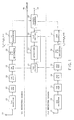
- a diversity receiving system comprises a plurality of receiving branches (two branches are shown).
- a first receiving branch comprises a first receiving antenna 21, a first receiver 22 coupled to the first receiving antenna 21, a first demodulator (DEM) 23 coupled to the first receiver 22, a first analog/digital convertor (A/D) 24 coupled to the first demodulator 23, a first random access memory (RAM) 25 coupled to the first analog/digital convertor 24, a first propagation path property (P.P.) estimator 26 coupled to the first RAM 25, and a first classifier 27 coupled to the first propagation path property estimator 26.
- DEM demodulator
- A/D analog/digital convertor
- RAM random access memory
- P.P. propagation path property estimator
- a second receiving branch also comprises a second receiving antenna 31, a second receiver 32 coupled to the second receiving antenna 31, a second demodulator (DEM) 33 coupled to the second receiver 32, a second analog/digital convertor (A/D) 34 coupled to the second demodulator 33, a second random access memory (RAM) 35 coupled to the first analog/digital convertor 34, a second propagation path property (P.P.) estimator 36 coupled to the second RAM 35, and a second classifier 37 coupled to the second propagation path property estimator 36.
- DEM demodulator
- A/D analog/digital convertor
- RAM random access memory
- P.P. propagation path property estimator
- the shown diversity receiving system further comprises a processing system for selecting one of the first and second receiving branches to equalize a demodulated signal from the selected receiving branch.
- the processing system comprises a first switch 41 coupled to the first and the second RAMs 25 and 35, a second switch 42 coupled to the first and the second classifiers 27 and 37, an equalizer 43 connected to the first and the second switches 41 and 42, and a branch selector 44 coupled to the first and the second classifiers 27 and 37.
- the branch selector 44 is provided with a terminal 45 for receiving a threshold or a reference value V which will later be described.
- the binary-phase-shift-keying is used as a modulation in a transmitter.
- a digital signal having a symbol rate comprises a data signal portion and a training signal portion.
- the transmitter transmits the digital signal as a transmission signal.
- the transmission signal from a transmitter propagates to the first and the second receiving antennas 21 and 31 through a multipath.
- a signal incoming through each of the first and the second antennas 21 and 31 is received at each of the first and the second receivers 22 and 32 and is thereafter demodulated at each of the first and the second demodulators 23 and 33.
- the demodulated signal is converted into a converted digital signal with a sampling rate equal to the symbol rate at each of the first and the second analog/digital convertors 24 and 34.
- Each of the first and the second receivers 22 and 32, each of the first and the second demodulators 23 and 33, and each of the first and the second analog/digital convertors 24 and 34 operate as a receiving means for processing the incoming signal to produce the converted digital signal as a digital reception signal.
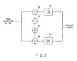
- each of the first and the second demodulators 23 and 24 comprises an oscillator 51 for oscillating a local signal, a first mixer 52 for frequency mixing the local signal and a reception signal from each of the first and the second receivers 23 and 33 to produce a first mixed signal, a phase shifter 53 for phase-shifting the local signal by ⁇ /2 to produce a phase shifted signal, a second mixer 54 for frequency mixing the reception signal and the phase-shifted signal to produce a second mixed signal, and a first and a second lowpass filter (LPF) 55 and 56 for filtering the first and the second mixed signals to produce a complex signal as a demodulated signal.
- LPF lowpass filter
- the converted digital signal from each of the first and the second analog/digital convertors 24 and 34 is stored or held in each of the first and the second RAMs 25 and 35 which operates as a holding means.
- the converted digital signal comprises the data signal portion and the training signal portion.
- Each of the first and the second propagation path property estimators 26 and 36 estimates a transmission property of the propagation path from the transmitter to each of the first and the second receiving antennas 21 and 31 by use of the training signal portion in the converted digital signal stored in each of the first and the second RAMs 25 and 35.
- the training signal comprises leading five symbols, ending five symbols and middle sixteen symbols (twenty-six (26) symbols in total) in the present embodiment.
- An autocorrelation function between the training signal of twenty-six symbols and the middle sixteen symbols is represented by an impulse over a range of -5T to +5T (T is a time duration of a single symbol) as shown in Fig. 4. It is possible by use of the training signal of which the autocorrelation function is represented by the impulse to estimate the property of the propagation path.
- each of the first and the second propagation path property estimators 26 and 36 comprises a sixteen-stage shift register 61 which comprises 15 delay elements (T) cascaded, an input terminal 62 and sixteen taps connected to sixteen multipliers 63-1 through 63-16, respectively.
- the training signal portion is time-serially applied from each of the first and the second RAMs 25 and 35 to the input terminal 62.
- a register 64 of sixteen stages is preset with the middle sixteen (16) symbols of the training signal portion.
- the middle sixteen (16) symbols are supplied from the register 64 to the sixteen multipliers 63-1 through 63-16 as reference signals, respectively, so that a signal on each of the sixteen taps of the shift register 61 is multiplied by each of the reference signals from the register 64 at each of the multipliers 63-1 through 63-16 to produce a multiplied signal.
- An adder 65 adds sixteen multiplied signals from the sixteen multipliers 63-1 through 63-16 one another to produce an added signal as a crosscorrelation function value at an output terminal 66.
- Each of the first and the second estimator 26 and 36 carries out an estimation operation from a time instant when the leading or start symbol (0-th bit in Fig.
- the former is represented by h a (-5) through h a (+5) and the latter is represented by h b (-5) through h b (+5).
- each of the first and the second classifiers 27 and 37 classifies the estimated impulse responses from each of the first and the second propagation path property estimators 26 and 36 into two groups, one of the two groups being significant components to the equalizer 43 and the other being insignificant components to the equalizer 43.
- Each of the first and the second classifiers 27 and 37 supplies the significant components to the second switch 42 and supplies the significant and the insignificant components to the branch selector 44.
- the equalizer 43 can equalize five of the estimated impulse responses h(-5) through h(+5) which are significant components.
- the significant components are represented by h(j) through h(j+4) which meet or satisfy the following equation:
- the insignificant components are h(i) except h(j) through h(j+4) and are residual intersymbol interference components which can not be equalized by the equalizer 43.
- the first classifier 27 selects from h a (-5) through h a (+5) first significant components h a (j) through h a (j+4) and delivers the first significant components to the second switch 42 and delivers the first significant components and the remaining or first insignificant components to the branch selector 44.
- the second classifier 37 selects from h b (-5) through h b (+5) second significant components h b (j) through h b (j+4) and delivers the second significant components to the second switch 42 and delivers the second significant components and the remaining or second insignificant components to the branch selector 44.
- the branch selector 44 receives the significant components and the insignificant components from each of the first and the second classifiers 27 and 37 and calculates a power ⁇ of the significant components and a power ⁇ of the insignificant components.
- the significant components are respectively squared and then added to produce the power ⁇ . That is, ⁇ is represented by:
- the power ⁇ is obtained by squaring the insignificant components and then summing them.
- the insignificant component power ⁇ comprises error components and noise components and has a small value so that the second ratio U is nearly equal to 1.
- the insignificant component power ⁇ comprises the residual intersymbol interference components as well as the error components and the noise components so that the second ratio U has a relatively small value.
- the significant component power ⁇ , the insignificant component power ⁇ , the first ratio S, the second ratio U, and the sum P calculated from the first significant components and the first insignificant components from the first classifier 27 to the branch selector 44 are represented by ⁇ a , ⁇ a , S a , U a , and P a , respectively.
- Those calculated from the second significant components and the second insignificant components from the second classifier 37 to the branch selector 44 are represented by ⁇ b , ⁇ b , S b , U b , and P b , respectiveley.
- the branch selector 44 is supplied with the threshold value V as a reference signal for the second ratio U through the terminal 45.
- the branch selector 44 compares the threshold value V with the second ratios U a and U b .
- the first ratios S a and S b are selected as parameters for selecting one of the first and the second receiving branches.
- the branch selector 44 compares S a and S b and produces a selection signal for selecting a specific one of the first and the second receiving branches when the specific receiving branch provides a larger one of S a and S b .
- the selection signal is applied to the first and the second switches 41 and 42.
- the first and second switches 41 and 42 operate to connect a specific RAM and a specific classifier in the specific receiving branch to the equalizer 43.
- the first receiving branch is the specific receiving branch and the first RAM 25 and the first classifier 27 are the specific RAM and the specific classifier.
- the equalizer 43 receives the data signal from the first RAM 25 as an input data signal and equalizes the input data signal by use of the first significant components from the first classifier 27.
- the equalizer 43 receives the data signal from the second RAM 35 as an input data signal and equalizes the input data signal by use of the second significant components from the second classifier 37.
- the powers P a and P b are selected as parameters for selecting one of the first and the second receiving branches.
- the branch selector 44 compares P a and P b and produces the selection signal for selecting one of the first and the second receiving branches as a specific receiving branch.
- One of the first and the second receiving branches which provides a larger one of P a and P b is selected as the specific receiving branch.
- a maximum likelihood sequence estimator using the Viterbi algorithm can be used as the equalizer 43.
- the equalizer shown therein comprises a branch metric arithmetic circuit 71, a Viterbi processor 72, and a state transition controller 73.
- a Trellis diagram of the Viterbi processor 72 is described in connection with equallization of intersymbol interference over a time duration of 5T caused by the impulse responses of the propagation path.
- a state S at a time k is defined by a series of all transmitted symbols S0, S1, S2, and S3 interfering the k-th symbol and is represented by S(S0, S1, S2, S3; k). Accordingly, a state transition from a time k to another time (k+1) is defined by a series of five transmitted symbols T0, T1, T2, T3, and T4.
- T0, T1, T2, and T3 are S0, S1, S2, and S3 at a time k
- T1, T2, T3, and T4 are S0, S1, S2, and S3 at a time (k+1).
- the Viterbi processor is one for carrying out demodulation according to a branch metric corresponding to all of possible state transitions from a time k to another time (k+1), as described in detail in a paper by J. F. Hayes, entitled "The Viterbi algorithm Applied To Digital Data Transmission” IEEE Communication Society, 1975, No. 13.
- the branch metric corresponding to the all possible state transitions can be obtained in the following manner.
- the state transition controller 73 sequentially produces all possible state transitions (T0, T1, T2, T3, T4) and makes the branch metric arithmetic circuit 71 and the Viterbi processor 72 calculate the branch metric for a desired state transition.
- the branch metric arithmetic circuit 71 comprises a matched filter 74, a branch metric fixed component arithmetic circuit 75 and a branch metric combiner 76.
- the branch metric fixed component arithmetic circuit 75 and the branch metric combiner 76 calculate the branch metrics corresponding to the state transition of (T0, T1, T2, T3, T4) supplied from the state transition controller 73.
- the calculated branch metric is supplied to the Viterbi processor 72.
- the Viterbi processor 72 is also supplied with the state transition (T0, T1, T2, T3, T4) from the state transition controller 73 and processes the branch metrics from the branch metric combiner 76 according to the Viterbi algorithm. The operation is repeated for sequential state transitions and the processed results are obtained from the terminal 46 as the equalized signal.
- an example of the matched filter 74 is a transversal filter.
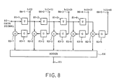
- the transvesal filter 74 comprises four delay circuit (T) 81-1 through 81-4 cascaded to each other, five multipliers 82-1 through 82-5, five tap gains 83-1 through 83-5 and an adder 84, as known in the art.
- the data signal is applied to the cascaded delay elements through an input terminal 80 and five significant components h(j) through h(j+4) are applied to the tap gains (G) 83-1 through 83-5 through tap gain terminals 86-1 through 86-5, respectively.
- the tap gains (G) obtain from the significant components h(j) through h(j+4) conjugate complex components h(j)* through h(j+4)* which are time-inverted.
- the time inverted conjugate components are applied to the mulitpliers 82-1 through 82-5 and are multiplied by the digital data signal to produce multiplied signals.
- the mulitplied signals are added at the adder 84 and the added signal is deliverd to the branch metric combiner 76 through an output terminal 85.
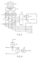
- an example of the branch metric fixed component arithmetic circuit 75 comprises an arithmetic circuit 91 for calculating real components r(1) through r(4) from the significant components h(j) through h(j+4) and their conjugate complex components h(j+1)* through h(j+4)* according to the following equation (2):
- the significant components h(j) through h(j+4) are applied to the arithmetic circuit 91 through five terminals 92-1 through 92-5.
- the calculated real components r(1) through r(4) are temporarily held at a register 93.
- Another register 94 is supplied with the the series of symbols T0, T1, T2, and T3 from the state transition controller 73 through terminals 95-0 through 95-3.
- Another register 96 is supplied with a symbol T4 from the state transition controller 73 through a terminal 95-4.
- the real components r(1) through r(4) in the register 93 and the symbols T3 through T0 in the register 94 are multiplied at multipliers 97-1 through 97-4, respectively.
- the multiplied signals are summed at an adder 98 and the resultant sum is multiplied by T4 in the register 96 at a multiplier 99.
- a resultant signal is applied to the branch metric combiner 76 through a terminal 100 as a branch metric fixed component.
- an example of the branch metric combiner 76 comprises a register 101 for holding T4 supplied from the state transition controller 73 through a terminal 102, a multiplier 103 for multiplying T4 in the register 101 by the filter output z(k) from the matched filter 74, an adder 105 for adding the multiplied signal from the multiplier 103 and the branch metric fixed component b(T0, T1, T2, T3, T4) from the branch metric fixed component arithmetic circuit 75 through a terminal 106 and a real component deriving circuit 107 for deriving a real component from the resultant added signal from the adder 105.
- the real component deriving circuit 107 delivers the derived real component as the branch metric signal B(T0, T1, T2, T3, T4) to the Viterbi processor 72 through a terminal 108.
- the diversity system shown in Fig. 1 was simulated for a propagation path model (I) which comprises a direct wave and a delayed wave (with 3T delay) caused by any reflection.
- the simulated result is shown in Fig. 11.
- the figure shows curves of the bit error rate (B.E.R.) in response to the signal to noise ratio (Eb/No). The curves are measured for the single branch and various values of the threshold V.
- the reception performance is improved by a suitable value for the threshold V.
- the shown embodiment comprises two receiving branches but can be provided with three or more receiving branches which are commonly connected to the first and the second switches and the branch selector.
Landscapes
- Engineering & Computer Science (AREA)
- Computer Networks & Wireless Communication (AREA)
- Signal Processing (AREA)
- Radio Transmission System (AREA)
- Cable Transmission Systems, Equalization Of Radio And Reduction Of Echo (AREA)
- Circuits Of Receivers In General (AREA)
Applications Claiming Priority (2)
| Application Number | Priority Date | Filing Date | Title |
|---|---|---|---|
| JP185427/89 | 1989-07-17 | ||
| JP18542789 | 1989-07-17 |
Publications (3)
| Publication Number | Publication Date |
|---|---|
| EP0409171A2 true EP0409171A2 (fr) | 1991-01-23 |
| EP0409171A3 EP0409171A3 (en) | 1992-11-25 |
| EP0409171B1 EP0409171B1 (fr) | 1996-03-20 |
Family
ID=16170597
Family Applications (1)
| Application Number | Title | Priority Date | Filing Date |
|---|---|---|---|
| EP90113688A Expired - Lifetime EP0409171B1 (fr) | 1989-07-17 | 1990-07-17 | Système de réception à diversité pour utilisation en radiocommunications numériques avec des moyens de sélection de branches par estimation des propriétés des chemins de propagation |
Country Status (7)
| Country | Link |
|---|---|
| US (1) | US5065411A (fr) |
| EP (1) | EP0409171B1 (fr) |
| JP (1) | JP2556179B2 (fr) |
| AU (1) | AU625945B2 (fr) |
| CA (1) | CA2021232C (fr) |
| DE (1) | DE69025997T2 (fr) |
| NO (1) | NO302550B1 (fr) |
Cited By (3)
| Publication number | Priority date | Publication date | Assignee | Title |
|---|---|---|---|---|
| EP0500326A3 (en) * | 1991-02-22 | 1992-09-02 | Nec Corporation | Digital mobile communication terminal equipment and receiving method therefor |
| DE4139059A1 (de) * | 1991-11-28 | 1993-06-03 | Daimler Benz Ag | Digitales nachrichtenuebertragungssystem |
| US5995499A (en) * | 1994-10-07 | 1999-11-30 | Nokia Telecommunications Oy | Signal detection in a TDMA system |
Families Citing this family (32)
| Publication number | Priority date | Publication date | Assignee | Title |
|---|---|---|---|---|
| DE69024525T2 (de) * | 1989-05-02 | 1996-05-15 | Nippon Electric Co | TDMA-Raumdiversity-Empfänger |
| IT1230284B (it) * | 1989-06-15 | 1991-10-18 | Italtel Spa | Procedimento e dispositivo per la ricezione di segnali in sistemi radiomobili digitali. |
| CA2037824C (fr) * | 1990-03-20 | 1999-11-09 | Hiroshi Kubo | Circuit fonctionnant en diversite et circuit d'evaluation de la phase de trame (ou du temps d'echantillonnage) utilisant ce circuit |
| DE69129768T2 (de) * | 1990-03-30 | 1999-02-25 | Nec Corp., Tokio/Tokyo | Störungsunempfindlicher Raumdiversityempfänger |
| FR2661578A1 (fr) * | 1990-04-27 | 1991-10-31 | Trt Telecom Radio Electr | Dispositif de commutation dynamique pour le masquage d'erreurs dans un systeme a doublement du conduit numerique. |
| US5272726A (en) * | 1990-07-31 | 1993-12-21 | Nec Corporation | Blind type sequence estimator for use in communications system |
| GB2247812B (en) * | 1990-09-06 | 1994-08-31 | Motorola Inc | Equalizer for linear modulated signal |
| GB9023605D0 (en) * | 1990-10-30 | 1990-12-12 | British Telecomm | Digital radio |
| JP2621685B2 (ja) * | 1991-05-29 | 1997-06-18 | 日本電気株式会社 | 適応型最尤系列推定装置 |
| US5263026A (en) * | 1991-06-27 | 1993-11-16 | Hughes Aircraft Company | Maximum likelihood sequence estimation based equalization within a mobile digital cellular receiver |
| US5214675A (en) * | 1991-07-02 | 1993-05-25 | Motorola, Inc. | System and method for calculating channel gain and noise variance of a communication channel |
| JP2683665B2 (ja) * | 1991-11-27 | 1997-12-03 | 日本電気株式会社 | 最尤系列推定装置 |
| JP3033308B2 (ja) * | 1991-12-25 | 2000-04-17 | 松下電器産業株式会社 | 合成ダイバーシチ受信機 |
| IT1258807B (it) * | 1992-01-22 | 1996-02-29 | Alcatel Italia | Metodo e sistema per la sincronizzazione di segnali mutuamente interferenti in trasmissioni radio numeriche con riuso di frequenza |
| US5319677A (en) * | 1992-05-12 | 1994-06-07 | Hughes Aircraft Company | Diversity combiner with MLSE for digital cellular radio |
| US5841816A (en) * | 1992-10-22 | 1998-11-24 | Ericsson Inc. | Diversity Pi/4-DQPSK demodulation |
| US5289499A (en) * | 1992-12-29 | 1994-02-22 | At&T Bell Laboratories | Diversity for direct-sequence spread spectrum systems |
| US5854808A (en) * | 1993-09-14 | 1998-12-29 | Pacific Communication Sciences | Methods and apparatus for detecting the presence of a prescribed signal in a channel of a communications system |
| US5574750A (en) * | 1993-09-14 | 1996-11-12 | Pacific Communication Sciences, Inc. | Methods and apparatus for detecting a cellular digital packet data (CDPD) carrier |
| US5550870A (en) * | 1994-03-02 | 1996-08-27 | Lucent Technologies Inc. | Viterbi processor |
| JPH10501395A (ja) * | 1994-06-03 | 1998-02-03 | テレフオンアクチーボラゲツト エル エム エリクソン | アンテナ用ダイバシティ結合 |
| US5796777A (en) * | 1996-02-27 | 1998-08-18 | Motorola, Inc. | Apparatus and method for digitizing and detecting a received radio frequency signal |
| SE9702370L (sv) * | 1997-06-19 | 1998-12-20 | Ericsson Telefon Ab L M | Balanserad diversitet |
| US6304624B1 (en) * | 1997-10-24 | 2001-10-16 | Fujitsu Limited | Coherent detecting method using a pilot symbol and a tentatively determined data symbol, a mobile communication receiver and an interference removing apparatus using the coherent detecting method |
| US6018647A (en) * | 1997-11-10 | 2000-01-25 | Electrocom Communication Systems, Inc. | Diversity reception system |
| GB9810686D0 (en) * | 1998-05-19 | 1998-07-15 | King S College London | Dual direction estimator |
| JP2000341183A (ja) * | 1999-05-31 | 2000-12-08 | Matsushita Electric Ind Co Ltd | 受信装置 |
| US6560299B1 (en) * | 1999-07-30 | 2003-05-06 | Christopher H Strolle | Diversity receiver with joint signal processing |
| US6151358A (en) * | 1999-08-11 | 2000-11-21 | Motorola, Inc. | Method and apparatus, and computer program for producing filter coefficients for equalizers |
| JP3546833B2 (ja) * | 2000-11-06 | 2004-07-28 | 日本電気株式会社 | 無線受信装置及び高速等化処理方法 |
| DE10307021A1 (de) * | 2003-02-20 | 2004-10-07 | Newlogic Technologies Ag | Adaptives Equalizersystem in integrierten drahtlosen Empfängern |
| JP4079197B1 (ja) * | 2007-02-06 | 2008-04-23 | 松下電器産業株式会社 | 受信装置とこれを用いた受信システム |
Family Cites Families (11)
| Publication number | Priority date | Publication date | Assignee | Title |
|---|---|---|---|---|
| US4935940A (en) * | 1967-05-24 | 1990-06-19 | The United States Of America As Represented By The Secretary Of The Army | Interference-proof reception of radio signals using frequency hopping techniques |
| US4281411A (en) * | 1979-06-25 | 1981-07-28 | Signatron, Inc. | High speed digital communication receiver |
| US4384358A (en) * | 1980-01-28 | 1983-05-17 | Nippon Electric Co., Ltd. | Space-diversity broad-band digital radio receiver |
| DE3427058A1 (de) * | 1984-07-23 | 1986-02-06 | Standard Elektrik Lorenz Ag, 7000 Stuttgart | Empfaenger fuer bandgespreizte signale |
| US4734920A (en) * | 1984-10-10 | 1988-03-29 | Paradyne Corporation | High speed modem for multiple communication circuits |
| US4748682A (en) * | 1985-01-08 | 1988-05-31 | Mitsubishi Denki Kabushiki Kaisha | Combined diversity receiving apparatus |
| DE3634439A1 (de) * | 1986-10-09 | 1988-04-14 | Blaupunkt Werke Gmbh | Verfahren und schaltungsanordnung zum empfang von radiowellen |
| GB2198913B (en) * | 1986-12-11 | 1990-12-19 | Plessey Co Plc | Troposcatter modem receiver |
| US4733402A (en) * | 1987-04-23 | 1988-03-22 | Signatron, Inc. | Adaptive filter equalizer systems |
| JP2622972B2 (ja) * | 1987-09-17 | 1997-06-25 | 三洋電機株式会社 | Fmラジオ受信機 |
| US4884272A (en) * | 1988-02-10 | 1989-11-28 | Mcconnell Peter R H | Maximum likelihood diversity receiver |
-
1990
- 1990-07-16 CA CA002021232A patent/CA2021232C/fr not_active Expired - Fee Related
- 1990-07-17 DE DE69025997T patent/DE69025997T2/de not_active Expired - Fee Related
- 1990-07-17 EP EP90113688A patent/EP0409171B1/fr not_active Expired - Lifetime
- 1990-07-17 AU AU59127/90A patent/AU625945B2/en not_active Ceased
- 1990-07-17 US US07/553,287 patent/US5065411A/en not_active Expired - Lifetime
- 1990-07-17 JP JP2187020A patent/JP2556179B2/ja not_active Expired - Lifetime
- 1990-07-17 NO NO903180A patent/NO302550B1/no not_active IP Right Cessation
Cited By (4)
| Publication number | Priority date | Publication date | Assignee | Title |
|---|---|---|---|---|
| EP0500326A3 (en) * | 1991-02-22 | 1992-09-02 | Nec Corporation | Digital mobile communication terminal equipment and receiving method therefor |
| DE4139059A1 (de) * | 1991-11-28 | 1993-06-03 | Daimler Benz Ag | Digitales nachrichtenuebertragungssystem |
| DE4139059C2 (de) * | 1991-11-28 | 1999-04-15 | Daimler Benz Aerospace Ag | Digitales Nachrichtenübertragungssystem |
| US5995499A (en) * | 1994-10-07 | 1999-11-30 | Nokia Telecommunications Oy | Signal detection in a TDMA system |
Also Published As
| Publication number | Publication date |
|---|---|
| NO903180D0 (no) | 1990-07-17 |
| CA2021232C (fr) | 1993-09-21 |
| NO903180L (no) | 1991-01-18 |
| AU5912790A (en) | 1991-01-17 |
| EP0409171B1 (fr) | 1996-03-20 |
| AU625945B2 (en) | 1992-07-16 |
| DE69025997T2 (de) | 1996-08-29 |
| JPH03214819A (ja) | 1991-09-20 |
| EP0409171A3 (en) | 1992-11-25 |
| US5065411A (en) | 1991-11-12 |
| NO302550B1 (no) | 1998-03-16 |
| DE69025997D1 (de) | 1996-04-25 |
| JP2556179B2 (ja) | 1996-11-20 |
| CA2021232A1 (fr) | 1991-01-18 |
Similar Documents
| Publication | Publication Date | Title |
|---|---|---|
| EP0409171B1 (fr) | Système de réception à diversité pour utilisation en radiocommunications numériques avec des moyens de sélection de branches par estimation des propriétés des chemins de propagation | |
| US4733402A (en) | Adaptive filter equalizer systems | |
| JP4010348B2 (ja) | 適応型直並列混合雑音除去方法 | |
| JP2715662B2 (ja) | 時分割信号のダイバーシチ受信のための方法および装置 | |
| JP3375139B2 (ja) | アダプティブアレイ送受信機 | |
| EP0925652B1 (fr) | Demodulation coherente avec estimation de canal a commande decisionnelle pour communication numerique | |
| EP0615347A1 (fr) | Recepteur a egalisation adaptative et recepteur a estimation de sequence a probabilite maximum | |
| US20060234662A1 (en) | Low complexity equalizer for radio receiver | |
| US5335251A (en) | Diversity receiver | |
| WO1998051030A1 (fr) | Procede et systeme permettant de determiner le rapport puissance de signal/puissance de l'interference plus bruit (sinr) dans un systeme de communication | |
| EP0397386B1 (fr) | Dispositif récepteur à diversité pour signaux numériques | |
| US20070030827A1 (en) | Channel estimation in cdma communications systems using both lower power pilot channel and higher power date channel | |
| EP0477183B1 (fr) | Recepteur radio mobile numerique a diversite spatiale et procede associe | |
| EP1176733A1 (fr) | Recepteur et procede de reception pour communication a spectre etale | |
| JP3235774B2 (ja) | アダプティブ・アレー受信機 | |
| JP2000188568A (ja) | 受信装置 | |
| US20040097204A1 (en) | Multi-subscriber detection using a rake receiver structure | |
| JP3424723B2 (ja) | 適応等化器 | |
| JPH10336083A (ja) | アダプティブアレイ受信機 | |
| CN1165185C (zh) | 码分多址系统中导频及数据联合信道估计方法及其装置 | |
| JP2600970B2 (ja) | ダイバーシティ受信装置 | |
| JP3611933B2 (ja) | 送信ダイバーシチを行なう送受信装置 | |
| JP2989268B2 (ja) | 適応等化受信機及び最尤系列推定受信機 | |
| JP4470798B2 (ja) | 無線通信装置及び方法 | |
| JPH09331281A (ja) | 送信ダイバーシチを行なう送受信装置 |
Legal Events
| Date | Code | Title | Description |
|---|---|---|---|
| PUAI | Public reference made under article 153(3) epc to a published international application that has entered the european phase |
Free format text: ORIGINAL CODE: 0009012 |
|
| 17P | Request for examination filed |
Effective date: 19900814 |
|
| AK | Designated contracting states |
Kind code of ref document: A2 Designated state(s): DE FR GB NL SE |
|
| PUAL | Search report despatched |
Free format text: ORIGINAL CODE: 0009013 |
|
| AK | Designated contracting states |
Kind code of ref document: A3 Designated state(s): DE FR GB NL SE |
|
| 17Q | First examination report despatched |
Effective date: 19950215 |
|
| GRAA | (expected) grant |
Free format text: ORIGINAL CODE: 0009210 |
|
| AK | Designated contracting states |
Kind code of ref document: B1 Designated state(s): DE FR GB NL SE |
|
| REF | Corresponds to: |
Ref document number: 69025997 Country of ref document: DE Date of ref document: 19960425 |
|
| ET | Fr: translation filed | ||
| PLBE | No opposition filed within time limit |
Free format text: ORIGINAL CODE: 0009261 |
|
| STAA | Information on the status of an ep patent application or granted ep patent |
Free format text: STATUS: NO OPPOSITION FILED WITHIN TIME LIMIT |
|
| 26N | No opposition filed | ||
| PGFP | Annual fee paid to national office [announced via postgrant information from national office to epo] |
Ref country code: SE Payment date: 19970703 Year of fee payment: 8 |
|
| PGFP | Annual fee paid to national office [announced via postgrant information from national office to epo] |
Ref country code: NL Payment date: 19970731 Year of fee payment: 8 |
|
| PG25 | Lapsed in a contracting state [announced via postgrant information from national office to epo] |
Ref country code: SE Free format text: LAPSE BECAUSE OF NON-PAYMENT OF DUE FEES Effective date: 19980718 |
|
| PG25 | Lapsed in a contracting state [announced via postgrant information from national office to epo] |
Ref country code: NL Free format text: LAPSE BECAUSE OF NON-PAYMENT OF DUE FEES Effective date: 19990201 |
|
| EUG | Se: european patent has lapsed |
Ref document number: 90113688.7 |
|
| NLV4 | Nl: lapsed or anulled due to non-payment of the annual fee |
Effective date: 19990201 |
|
| REG | Reference to a national code |
Ref country code: GB Ref legal event code: IF02 |
|
| PGFP | Annual fee paid to national office [announced via postgrant information from national office to epo] |
Ref country code: GB Payment date: 20060712 Year of fee payment: 17 |
|
| PGFP | Annual fee paid to national office [announced via postgrant information from national office to epo] |
Ref country code: DE Payment date: 20060713 Year of fee payment: 17 |
|
| PGFP | Annual fee paid to national office [announced via postgrant information from national office to epo] |
Ref country code: FR Payment date: 20060719 Year of fee payment: 17 |
|
| GBPC | Gb: european patent ceased through non-payment of renewal fee |
Effective date: 20070717 |
|
| PG25 | Lapsed in a contracting state [announced via postgrant information from national office to epo] |
Ref country code: DE Free format text: LAPSE BECAUSE OF NON-PAYMENT OF DUE FEES Effective date: 20080201 |
|
| PG25 | Lapsed in a contracting state [announced via postgrant information from national office to epo] |
Ref country code: GB Free format text: LAPSE BECAUSE OF NON-PAYMENT OF DUE FEES Effective date: 20070717 |
|
| REG | Reference to a national code |
Ref country code: FR Ref legal event code: ST Effective date: 20080331 |
|
| PG25 | Lapsed in a contracting state [announced via postgrant information from national office to epo] |
Ref country code: FR Free format text: LAPSE BECAUSE OF NON-PAYMENT OF DUE FEES Effective date: 20070731 |