EP0409183A2 - Système de traitement d'images - Google Patents
Système de traitement d'images Download PDFInfo
- Publication number
- EP0409183A2 EP0409183A2 EP90113704A EP90113704A EP0409183A2 EP 0409183 A2 EP0409183 A2 EP 0409183A2 EP 90113704 A EP90113704 A EP 90113704A EP 90113704 A EP90113704 A EP 90113704A EP 0409183 A2 EP0409183 A2 EP 0409183A2
- Authority
- EP
- European Patent Office
- Prior art keywords
- photosensitive body
- temperature
- image density
- image processing
- processing equipment
- Prior art date
- Legal status (The legal status is an assumption and is not a legal conclusion. Google has not performed a legal analysis and makes no representation as to the accuracy of the status listed.)
- Granted
Links
Images



Classifications
-
- G—PHYSICS
- G03—PHOTOGRAPHY; CINEMATOGRAPHY; ANALOGOUS TECHNIQUES USING WAVES OTHER THAN OPTICAL WAVES; ELECTROGRAPHY; HOLOGRAPHY
- G03G—ELECTROGRAPHY; ELECTROPHOTOGRAPHY; MAGNETOGRAPHY
- G03G15/00—Apparatus for electrographic processes using a charge pattern
- G03G15/50—Machine control of apparatus for electrographic processes using a charge pattern, e.g. regulating differents parts of the machine, multimode copiers, microprocessor control
- G03G15/5033—Machine control of apparatus for electrographic processes using a charge pattern, e.g. regulating differents parts of the machine, multimode copiers, microprocessor control by measuring the photoconductor characteristics, e.g. temperature, or the characteristics of an image on the photoconductor
-
- G—PHYSICS
- G03—PHOTOGRAPHY; CINEMATOGRAPHY; ANALOGOUS TECHNIQUES USING WAVES OTHER THAN OPTICAL WAVES; ELECTROGRAPHY; HOLOGRAPHY
- G03G—ELECTROGRAPHY; ELECTROPHOTOGRAPHY; MAGNETOGRAPHY
- G03G15/00—Apparatus for electrographic processes using a charge pattern
- G03G15/04—Apparatus for electrographic processes using a charge pattern for exposing, i.e. imagewise exposure by optically projecting the original image on a photoconductive recording material
- G03G15/043—Apparatus for electrographic processes using a charge pattern for exposing, i.e. imagewise exposure by optically projecting the original image on a photoconductive recording material with means for controlling illumination or exposure
-
- G—PHYSICS
- G03—PHOTOGRAPHY; CINEMATOGRAPHY; ANALOGOUS TECHNIQUES USING WAVES OTHER THAN OPTICAL WAVES; ELECTROGRAPHY; HOLOGRAPHY
- G03G—ELECTROGRAPHY; ELECTROPHOTOGRAPHY; MAGNETOGRAPHY
- G03G15/00—Apparatus for electrographic processes using a charge pattern
- G03G15/50—Machine control of apparatus for electrographic processes using a charge pattern, e.g. regulating differents parts of the machine, multimode copiers, microprocessor control
- G03G15/5033—Machine control of apparatus for electrographic processes using a charge pattern, e.g. regulating differents parts of the machine, multimode copiers, microprocessor control by measuring the photoconductor characteristics, e.g. temperature, or the characteristics of an image on the photoconductor
- G03G15/5045—Detecting the temperature
-
- G—PHYSICS
- G03—PHOTOGRAPHY; CINEMATOGRAPHY; ANALOGOUS TECHNIQUES USING WAVES OTHER THAN OPTICAL WAVES; ELECTROGRAPHY; HOLOGRAPHY
- G03G—ELECTROGRAPHY; ELECTROPHOTOGRAPHY; MAGNETOGRAPHY
- G03G2215/00—Apparatus for electrophotographic processes
- G03G2215/00025—Machine control, e.g. regulating different parts of the machine
- G03G2215/00071—Machine control, e.g. regulating different parts of the machine by measuring the photoconductor or its environmental characteristics
- G03G2215/00084—Machine control, e.g. regulating different parts of the machine by measuring the photoconductor or its environmental characteristics the characteristic being the temperature
Definitions
- This invention relates to an improvement of an image processing equipment of a copying machine or a printer for instance, by which the image density setting conditions can be adjusted according to the temperature change of a photosensitive body and more particularly relates to an image processing equipment by which a beautiful image density can be secured at all times by selectively determining proper image density setting conditions even in the case that such an irreversible characteristic deterioration of a photosensitive body as electrification power, sensitivity, etc. occurs.
- the image density is kept constant by, for instance, lowering (increasing) the voltage of an exposure lamp according to increase (or decrease) of the temperature of a photosensitive body. Therefore, such a control method as shown in the above can correspond to so-called reversible changes i.e., the characteristic of the photosensitive body returns to the original state thereof as the temperature of the photosensitive body returns as before. However, it can not correspond to the case that the characteristic of the photosensitive body changes irreversibly.
- the first invention is an image processing equipment which can detect irreversible characteristic deterioration of a photosensitive body and change the relation of the image density conditions for the temperature of a photosensitive body according to the irreversible characteristic deterioration in an image density adjusting method of the image processing equipment so composed as to adjust the image density setting conditions to the temperature changes of the photosensitive body.
- the second invention is an image processing equipment so composed as to adjust he image density setting conditions to the temperature changes of a photosensitive body and furnished with means for detecting irreversible characteristic deterioration of a photosensitive body and means for changing the relation of the image density conditions for the temperature of the photosensitive body according to the irreversible characteristic deterioration.
- the relationship between the temperature of the photosensitive body and the image density conditions which have suited to reversible changes up to now will not be able to be applied. Instead, the relationship between the temperature of a photosensitive body and the image density condition which suits to irreversible changes will be applied.
- the third invention is an image processing equipment so composed as to adjust the image density setting conditions according to the temperature changes of a photosensitive body and comprising deterioration detecting means for detecting the irreversible characteristic deterioration of the photosensitive body, temperature detecting means for detecting the temperature of the photosensitive body, condition memorizing means for memorizing escalational image density setting conditions according to the temperature of the photosensitive body, and control means for carrying out image processing and forming by selectively applying the image density setting conditions memorized in the condition memorizing means according to the temperature of the photosensitive body detected by the temperature detecting means when the photosensitive body characteristic deterioration exceeding an appointed level is detected by the deterioration detecting means.
- the image density setting condition best suited to the temperature of the photosensitive body at this time is selected and is adopted to the image processing and forming, thereby causing proper image density setting conditions to be selectively adopted according to the temperature of the photosensitive body.
- the image density setting conditions are escalationally memorized according to the temperature of the photosensitive body, any large-scaled memory capacity is not needed and the control method can be also simplified.
- the image processing equipment has an exposure lamp 3 by which a document 2 set on a document table 1 is exposed to light and scanned in accompanying with movements of the document table 1.
- a main charger 5, a developing unit 7, a transcribing charger 8, a separating charger 9, a cleaner 10 and a thermister 11 for measuring the ambient temperature of the photosensitive body drum 4 are arranged in this order in the vicinity of an organic photosensitive drum (photosensitive body) 4 which is rotatably attached to the underside of the document table 1.
- the thermister 11 constitutes one of the examples of the temperature detecting means.
- the image processing equipment "A" is such a type that the document table 1 can move to expose a document 1 to a lamp for scanning.
- the invention can be also applied to such a type that the exposure lamp 3 can move for light exposure and scanning.
- a charging voltage given to the main charger 5 may be selected as image density setting conditions, and a bias voltage given to the developing sleeve of the developing unit 7 may be also selected as image density setting conditions.
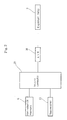
- Fig. 2 is a block diagram showing the signal system of the drive adjusting unit of the exposure lamp 3.
- Signals from the thermister 11 which can detect the surface temperature of the photosensitive body drum 4 from the ambient temperature are supplied to a micro computer 13 through an A/D converter and an 5/0 interface, which are not illustrated herein.
- a non-volatile memory 6 is connected to the micro computer 13. The non-volatile memory 6 is for memorizing the values of a counter described later to express the degree of the irreversible characteristic deterioration of the photosensitive body drum 4.
- an AVR 14 which drives the exposure lamp 3 at a constant voltage through an 5/0 interface and an A/D converter, which are not illustrated herein, is connected to the output side of the micro computer 13.
- the drive voltage (AVR output voltage) can be decreased since the sensitivity is increased as the temperature rises and the AVR output voltage can be increased as the sensitivity is lowered as the temperature goes down.
- the example shown in Fig. 3 shows that the sensitivity is not changed and becomes constant as the surface temperature of the photosensitive body drum 4 exceeds 40°C.
- this is applicable only under such a state that any irreversible characteristic deterioration does not occur in the photosensitive body.
- the AVR output compensation amount V(t) is escalationally changed when the temperature of the photosensitive body drum 4 is around 20°C and around 40°C, thereby causing the control to be simplified.
- the AVR output compensation amount V(t) when the drum temperature T is less than 20°C, the AVR output compensation amount V(t) shall be the compensation amount + 2V (constant) under the condition that there is no irreversible characteristic deterioration.
- the compensation amount V(t) when the drum temperature T is from 20°C to 40°C, the compensation amount V(t) shall be the compensation amount + 1V (constant) under the condition that there is no irreversible characteristic deterioration, and when the drum temperature T is more than 40°C, the compensation amount shall be set to the same AVR output compensation amount as that under the condition that there is no irreversible characteristic deterioration.
- the compensation amount may be modified as shown with the one-dashed line in Fig. 3 as described in the above, or may be modified as shown with the dashed lines.
- the feature of the invention exists in such a point that the conditions can be changed as shown in the above.
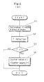
- Fig. 4 (a) shows the processing at the point when copying a sheet of paper is terminated
- Fig. 4 (b) shows the processing prior to copying a sheet of paper.
- step S1, S2, ... in the ensuing description show the number of the processing procedures (steps).
- the step S1 in Fig. 4 (a) as copying a sheet of paper is terminated, the surface temperature T of the photosensitive body drum 4 can be detected (in the step S2) by the output signals from the thermister 11.
- this drum temperature T is higher than an appointed temperature level To (in the step S3), the value C of the counter composed of the non-volatile memory 6 is incrementally increased by 1. Also, the value of the counter is reset when installing a copying machine or replacing the photosensitive body drum 4.
- the appointed temperature To is such a high temperature that if the photosensitive body drum 4 is exposed to the appointed temperature for a longer period of time the irreversible characteristic deterioration can occur.
- the appointed temperature is explained for instance as 50°C. Therefore, in the case that the drum temperature T is lower than the appointed temperature level To in the step S3, the value of the counter is not incrementally increased.
- the value C of the counter stored in the non-volatile memory 6 is compared with the appointed limit number Co of times as shown in the step S5 in Fig. 4.
- the value C of the counter exceeds the appointed limit number Co of times, it is judged that irreversible characteristic deterioration has occurred in the photosensitive drum 4, thereby causing the processing in the following steps S6 through S9 to be conducted. Therefore, means for realizing the function for judging the value C of the counter is one of the examples of the deterioration detecting means.
- the surface temperature T of the photosensitive body drum 4 is lower than an appointed partitioning temperature T1.
- This partitioning temperature is expressed with, for instance, 20°C in Fig. 3.
- the AVR output compensation amount V(t) is expressed with Vo (t) + Y1.
- Vo (t) is the AVR output compensation amount in the case that any irreversible characteristic deterioration is not yielded, and for instance, in the example shown in Fig. 3, the Vo is the value which changes according to the temperature as shown with the solid line.
- Y1 is a modifying portion for modifying the AVR output compensation amount when the degree of characteristic deterioration is changed from reversible to irreversible. It is for instance 2V in the example shown in Fig. 3 (Step S7).
- the T2 is another partitioning temperature which is higher than the T1 and is 40°C in the example in Fig. 3.
- the Y2 is the modified amount of the AVR output compensation amount during the period while the drum temperature is between T1 and T2, and in the example shown in Fig.3, IV corresponds to the modified amount thereof
- the processing in the step S10 is executed.
- the AVR output compensation amount image density setting conditions
- the AVR output voltage is next compensated by the compensation amount V(t) set in the step S11, thereby causing the exposure lamp 3 to be driven on the basis of the voltage and the copying processing (Step S12) to be carried out.
- the control means in the invention is for realizing the processing from the step S6 through the step S12.
- the drum temperature 4 is divided into three levels and the image density setting conditions are memorized to the three levels, respectively, thereby causing the image forming processing to be conducted by selectively applying these conditions.
- the escalational temperature range is not limited to the three levels as shown in the above. It can be set to two levels simply or can be set to four levels further in details.
- the drum temperature is higher than the T2
- the same level as that for the state in which irreversible characteristic deterioration does not occur is adopted.
- another proper characteristic is set according to the characteristic of the photosensitive body drum 4 and may be selected for application.
- the invention is not limited to an organic photosensitive body but can apply to all the types of photosensitive bodies in which irreversible characteristic deterioration may occur.
Landscapes
- Physics & Mathematics (AREA)
- General Physics & Mathematics (AREA)
- Engineering & Computer Science (AREA)
- Microelectronics & Electronic Packaging (AREA)
- Control Or Security For Electrophotography (AREA)
Applications Claiming Priority (4)
| Application Number | Priority Date | Filing Date | Title |
|---|---|---|---|
| JP185802/89 | 1989-07-18 | ||
| JP1185803A JPH0754408B2 (ja) | 1989-07-18 | 1989-07-18 | 画像形成装置 |
| JP185803/89 | 1989-07-18 | ||
| JP1185802A JPH0350566A (ja) | 1989-07-18 | 1989-07-18 | 画像形成装置 |
Publications (3)
| Publication Number | Publication Date |
|---|---|
| EP0409183A2 true EP0409183A2 (fr) | 1991-01-23 |
| EP0409183A3 EP0409183A3 (en) | 1991-05-22 |
| EP0409183B1 EP0409183B1 (fr) | 1994-06-08 |
Family
ID=26503339
Family Applications (1)
| Application Number | Title | Priority Date | Filing Date |
|---|---|---|---|
| EP90113704A Expired - Lifetime EP0409183B1 (fr) | 1989-07-18 | 1990-07-17 | Système de traitement d'images |
Country Status (3)
| Country | Link |
|---|---|
| US (1) | US5060022A (fr) |
| EP (1) | EP0409183B1 (fr) |
| DE (1) | DE69009606T2 (fr) |
Families Citing this family (1)
| Publication number | Priority date | Publication date | Assignee | Title |
|---|---|---|---|---|
| US5191362A (en) * | 1990-02-21 | 1993-03-02 | Tokyo Electric Co., Ltd. | Electrophotographic printing apparatus with a control system responsive to temperature changes |
Family Cites Families (6)
| Publication number | Priority date | Publication date | Assignee | Title |
|---|---|---|---|---|
| CA1091756A (fr) * | 1975-10-14 | 1980-12-16 | Eastman Kodak Company | Appareil electrophotographique a compensation des changements dans les proprietes sensitometriques des photoconducteurs |
| US4502777A (en) * | 1981-05-02 | 1985-03-05 | Minolta Camera Kabushiki Kaisha | Transfer type electrophotographic copying apparatus with substantially constant potential control of photosensitive member surface |
| JPS581165A (ja) * | 1981-06-26 | 1983-01-06 | Canon Inc | 電子写真方法 |
| US4508446A (en) * | 1982-02-09 | 1985-04-02 | Ricoh Company, Ltd. | Reproduction process control method |
| JPS63158572A (ja) * | 1986-12-23 | 1988-07-01 | Konica Corp | 感光体疲労回復を抑えた複写装置 |
| US4724461A (en) * | 1987-04-06 | 1988-02-09 | Eastman Kodak Company | Dynamic process control for electrostatographic machines |
-
1990
- 1990-07-13 US US07/553,752 patent/US5060022A/en not_active Expired - Lifetime
- 1990-07-17 EP EP90113704A patent/EP0409183B1/fr not_active Expired - Lifetime
- 1990-07-17 DE DE69009606T patent/DE69009606T2/de not_active Expired - Fee Related
Also Published As
| Publication number | Publication date |
|---|---|
| DE69009606T2 (de) | 1995-01-12 |
| EP0409183B1 (fr) | 1994-06-08 |
| US5060022A (en) | 1991-10-22 |
| DE69009606D1 (de) | 1994-07-14 |
| EP0409183A3 (en) | 1991-05-22 |
Similar Documents
| Publication | Publication Date | Title |
|---|---|---|
| US7113712B2 (en) | Image forming apparatus | |
| US5697031A (en) | Image forming apparatus and method for overlaid transfer of images | |
| EP0743785B1 (fr) | Imprimante numérique avec procédé électrophotographique | |
| US6983111B2 (en) | Image formation device and image formation method | |
| US5835235A (en) | Image forming apparatus which establishes image formation values using environmentally sensitive references | |
| EP0858008B1 (fr) | Dispositif de commande d'un appareil électrophotographique | |
| US5173734A (en) | Image forming apparatus using measured data to adjust the operation level | |
| US5574543A (en) | Image forming apparatus | |
| JPS60260066A (ja) | 電子写真の制御方法 | |
| US5513012A (en) | Image forming apparatus having density correction for image formation | |
| EP0409183A2 (fr) | Système de traitement d'images | |
| US5726759A (en) | Image forming apparatus | |
| US5918086A (en) | Image formation device | |
| US5845171A (en) | Technique for controlling developing voltage of image forming device | |
| JP3264947B2 (ja) | 画像形成装置 | |
| JPH05323740A (ja) | 画像形成装置 | |
| US5389955A (en) | Image forming apparatus directly correcting an image data in response to changes in image potential data | |
| US7116921B2 (en) | Method and apparatus to correct power source voltage variation in an image forming system | |
| JPS60189766A (ja) | 画像濃度制御装置 | |
| JPS6290671A (ja) | 複写機の露光レベル制御装置 | |
| JPH07115487B2 (ja) | 電子写真式印字装置 | |
| JPH07333923A (ja) | 電子写真式記録装置 | |
| JPH0651603A (ja) | 作像制御装置 | |
| JPH04306670A (ja) | 画像形成装置 | |
| JPH01289979A (ja) | 画像記録装置 |
Legal Events
| Date | Code | Title | Description |
|---|---|---|---|
| PUAI | Public reference made under article 153(3) epc to a published international application that has entered the european phase |
Free format text: ORIGINAL CODE: 0009012 |
|
| 17P | Request for examination filed |
Effective date: 19900814 |
|
| AK | Designated contracting states |
Kind code of ref document: A2 Designated state(s): DE FR GB NL |
|
| PUAL | Search report despatched |
Free format text: ORIGINAL CODE: 0009013 |
|
| AK | Designated contracting states |
Kind code of ref document: A3 Designated state(s): DE FR GB NL |
|
| 17Q | First examination report despatched |
Effective date: 19930215 |
|
| GRAA | (expected) grant |
Free format text: ORIGINAL CODE: 0009210 |
|
| AK | Designated contracting states |
Kind code of ref document: B1 Designated state(s): DE FR GB NL |
|
| REF | Corresponds to: |
Ref document number: 69009606 Country of ref document: DE Date of ref document: 19940714 |
|
| ET | Fr: translation filed | ||
| PLBE | No opposition filed within time limit |
Free format text: ORIGINAL CODE: 0009261 |
|
| STAA | Information on the status of an ep patent application or granted ep patent |
Free format text: STATUS: NO OPPOSITION FILED WITHIN TIME LIMIT |
|
| 26N | No opposition filed | ||
| PGFP | Annual fee paid to national office [announced via postgrant information from national office to epo] |
Ref country code: GB Payment date: 19970708 Year of fee payment: 8 |
|
| PGFP | Annual fee paid to national office [announced via postgrant information from national office to epo] |
Ref country code: FR Payment date: 19970709 Year of fee payment: 8 |
|
| PGFP | Annual fee paid to national office [announced via postgrant information from national office to epo] |
Ref country code: DE Payment date: 19970725 Year of fee payment: 8 |
|
| PGFP | Annual fee paid to national office [announced via postgrant information from national office to epo] |
Ref country code: NL Payment date: 19970731 Year of fee payment: 8 |
|
| PG25 | Lapsed in a contracting state [announced via postgrant information from national office to epo] |
Ref country code: GB Free format text: LAPSE BECAUSE OF NON-PAYMENT OF DUE FEES Effective date: 19980717 |
|
| PG25 | Lapsed in a contracting state [announced via postgrant information from national office to epo] |
Ref country code: NL Free format text: LAPSE BECAUSE OF NON-PAYMENT OF DUE FEES Effective date: 19990201 |
|
| GBPC | Gb: european patent ceased through non-payment of renewal fee |
Effective date: 19980717 |
|
| PG25 | Lapsed in a contracting state [announced via postgrant information from national office to epo] |
Ref country code: FR Free format text: LAPSE BECAUSE OF NON-PAYMENT OF DUE FEES Effective date: 19990331 |
|
| NLV4 | Nl: lapsed or anulled due to non-payment of the annual fee |
Effective date: 19990201 |
|
| PG25 | Lapsed in a contracting state [announced via postgrant information from national office to epo] |
Ref country code: DE Free format text: LAPSE BECAUSE OF NON-PAYMENT OF DUE FEES Effective date: 19990501 |
|
| REG | Reference to a national code |
Ref country code: FR Ref legal event code: ST |