EP0409342B1 - Système de fixation d'une touche à mouvement piano et appareil l'utilisant - Google Patents
Système de fixation d'une touche à mouvement piano et appareil l'utilisant Download PDFInfo
- Publication number
- EP0409342B1 EP0409342B1 EP90201928A EP90201928A EP0409342B1 EP 0409342 B1 EP0409342 B1 EP 0409342B1 EP 90201928 A EP90201928 A EP 90201928A EP 90201928 A EP90201928 A EP 90201928A EP 0409342 B1 EP0409342 B1 EP 0409342B1
- Authority
- EP
- European Patent Office
- Prior art keywords
- button
- support
- fastening system
- rest position
- strip
- Prior art date
- Legal status (The legal status is an assumption and is not a legal conclusion. Google has not performed a legal analysis and makes no representation as to the accuracy of the status listed.)
- Expired - Lifetime
Links
Images
Classifications
-
- H—ELECTRICITY
- H01—ELECTRIC ELEMENTS
- H01H—ELECTRIC SWITCHES; RELAYS; SELECTORS; EMERGENCY PROTECTIVE DEVICES
- H01H21/00—Switches operated by an operating part in the form of a pivotable member acted upon directly by a solid body, e.g. by a hand
- H01H21/02—Details
- H01H21/18—Movable parts; Contacts mounted thereon
- H01H21/22—Operating parts, e.g. handle
-
- H—ELECTRICITY
- H01—ELECTRIC ELEMENTS
- H01H—ELECTRIC SWITCHES; RELAYS; SELECTORS; EMERGENCY PROTECTIVE DEVICES
- H01H2221/00—Actuators
- H01H2221/036—Return force
- H01H2221/044—Elastic part on actuator or casing
Definitions
- the present invention relates to a system for fixing a control key on a support, said key being substantially flat, and having a freedom of movement of the piano type with a rest position and a control position, said key comprising a strip provided with a spoiler situated at a distance from the plane of the key at least equal to the thickness of the support, while the said support is provided with an opening which crosses its thickness so that the spoiler snaps onto the rear of the support after elastic penetration of the lamella into the opening of the support constitutes a means for positioning the button in its rest position on the support, return means for returning the button to the rest position after a control operation by pressing the key, and stops which prevent excessive insertion of the key into the support.
- Such control keys are used in audio and video devices, in particular car radios to control the various adjustments: tone, sound, ...; such a button acts, for example, on a switch which delivers a pulse each time the button is pressed.
- a system in accordance with the preamble is known from US Pat. No. 4,689,455 (Watanabe).
- the system according to this patent comprises a button provided with a strip ensuring the positioning of the button.
- the means for returning the key to the rest position consist of an elastic link between the strip and the key.
- the present invention aims to ensure that the button fixing system can best meet functional and aesthetic constraints including: large number of operations, positioning accuracy relative to the aesthetic facade, possibility of lighting by the inside the device, absence of mechanical noise in vibration.
- a fixing system in accordance with the preamble is particularly remarkable in that the opening of the support is in the form of a flattened T, in that the said button is provided with two other strips made of an elastic material, contiguous to the first and located on each side of the latter in the same plane perpendicular to the plane of the fingerboard, the assembly being arranged so that after elastic penetration of the central strip in the leg of the T and simultaneously of the two lateral strips in the wings of the T, the two lateral blades are supported in the wings of the T to constitute the said return means.
- Such a system is also very simple, inexpensive, easy to assemble and disassemble.
- it includes constraint means for putting said elastic strips in tension so that the positioning in the rest position does not include any play.
- said stressing means consist of an additional thickness disposed on the central strip.
- the stops which prevent excessive introduction of the key into the support are carried by the two lateral blades.
- said key further comprises a lower positioning tab made of elastic material perpendicular to the plane of the key, and provided with a snap-on spoiler for, by cooperating with a support opening, specifying the determination of the said rest position.
- the key is, in a way, subjected to a second preload which ensures perfect reproducibility of the rest position; this is essential in the general case where the key is a plastic part molded in a mold with several indentations and when several keys are mounted side by side.
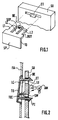
- Figure 1 shows the principle of the key and the support.
- Figure 2 shows, in section, the mounting system mounted.
- the support SU has, throughout its thickness, an opening ET in the form of a flattened 'T'.
- the TO key is operated by pressure exerted on the flat surface SP; this surface can obviously have other aspects than that shown.
- the key is provided with 3 strips L1, LC, L2 substantially perpendicular to the flat surface and having a thickness thin enough for the strips to be elastic.
- the thickness of the wings of the support T is slightly greater than the thickness of the side blades L1 and L2 so that they can penetrate it with the minimum of play; to facilitate the introduction of the key, provision may be made for slightly bevelling the end of the strips L1, L2 both in thickness and in width.
- the central strip LC is provided at its free end with a spoiler BE arranged to snap onto the support SU; for this purpose it is not wider than the leg of the T so that, during assembly of the system, the central strip folds down to pass the spoiler BE then returns to place for snap-fastening.
- the side slats are here provided with BUT side stops which prevent excessive introduction of the TO key into the support SU, thus the key is well positioned in depth by the spoiler BE and the BUT stops; other arrangements of the stops are also possible.
- the central strip LC has a slight excess thickness SEP next to the spoiler; after mounting, this extra thickness slightly spreads the central strip LC from the upper wall of the 'T' which has the effect of prestressing the elastic strips.
- SEP the thickness of the central strip LC
- the key does not wiggle in its housing in the event of vibration.
- Figure 2 shows an actual mounting example while Figure 1 rather shows the principle of operation.
- an FA facade is shown; it may happen that the facade and the support are only one and the same piece without modifying the principle of the positioning system according to the invention.
- the TO key in Figure 2 has an external appearance - rounded edges with skirt - more 'commercial' than that in Figure 1, but functionally it is the same.
- the central lamella LC with its spoiler BE is snapped into the opening AND of the support SU.
- the side slats are not visible in Figure 2.
- the position shown is the rest position.
- the TEC control pin When the key is pressed, the TEC control pin actuates the SW switch. They are here symbolically represented to show that it only takes a short stroke to perform the function of the piano-type movement.
- the elastic strips constitute the means for returning the control position to the rest position.
- the TO key in FIG. 2 also has a lower tab PI which, similar to the spoiler BE, snaps into the support SU.
- the role of the paw PI is only to precisely fix the rest position because it is arranged to constrain, without excess, the elastic strips.
- the position of the TO key with respect to the FA facade could be different from one key to another due to manufacturing dispersions, in particular with multi-cavity molds.
- such a fixing system has been produced with a plastic button 15x15 mm with strips of which the thickness is 0.7 mm, the width of 2.5 mm and the length of 6 mm.
- the fixing system according to the invention occupies little space and, therefore, it is possible to light the button from the rear with, for example, an AM bulb.
- the area of the support marked LU prefferably be empty, or translucent, for the light emitted by the bulb AM to illuminate the key from the rear to reveal an inscription or a drawing.
Landscapes
- Push-Button Switches (AREA)
- Electrophonic Musical Instruments (AREA)
Description
- La présente invention a pour objet un système de fixation d'une touche de commande sur un support, la dite touche étant sensiblement plane, et ayant une liberté de mouvement du type piano avec une position de repos et une position de commande, la dite touche comportant une lamelle pourvue d'un becquet situé à une distance du plan de la touche au moins égale à l'épaisseur du support cependant que le dit support est pourvu d'une ouverture qui traverse son épaisseur afin que le becquet s'encliquetant sur l'arrière du support après pénétration élastique de la lamelle dans l'ouverture du support constitue un moyen de positionnement de la touche dans sa position de repos sur le support, des moyens de rappel pour rappeler la touche en position de repos après une opération de commande par pression sur la touche, et des butées qui empêchent une introduction excessive de la touche dans le support.
- De telles touches de commande sont utilisées dans les appareils audio, vidéo, notamment les autoradios pour commander les divers réglages : tonalité, son,...; une telle touche agit, par exemple, sur un interrupteur qui délivre une impulsion lors de chaque pression exercée sur la touche.
- Un système conforme au préambule est connu du brevet US-4,689,455 (Watanabe). Le système selon ce brevet comporte une touche munie d'une lamelle assurant le positionnement de la touche. Les moyens de rappel de la touche en position de repos sont constitués par une laison élastique entre la lamelle et la touche.
- La présente invention a pour but d'assurer que le système de fixation de la touche puisse répondre au mieux à des contraintes fonctionnelles et esthétiques notamment : grand nombre de manoeuvres, précision de positionnement par rapport à la façade esthétique, possibilité d'éclairage par l'intérieur de l'appareil, absence de bruit mécanique en vibrations.
- Selon la présente invention, un système de fixation conforme au préambule est particulièrement remarquable en ce que l'ouverture du support est en forme de T aplati, en ce que la dite touche est pourvue de deux autres lamelles constituées d'un matériau élastique, contiguës à la première et situées de chaque côté de cette dernière dans un même plan perpendiculaires au plan de la touche, l'ensemble étant agencé pour que après pénétration élastique de la lamelle centrale dans la jambe du T et simultanément des deux lamelles latérales dans les ailes du T, les deux lamelles latérales prennent appui dans les ailes du T pour constituer les dits moyens de rappel.
- Un tel système est en outre très simple, peu coûteux, facile à monter et à démonter.
- Avantageusement, il comporte des moyens de contrainte pour mettre les dites lamelles élastiques en tension de telle sorte que le positionnement en position de repos ne comporte pas de jeu.
- Ainsi lorsque le système est soumis à des vibrations, c'est notamment le cas dans les autoradios, il ne produit pas de bruit mécanique.
- Préférentiellement, les dits moyens de contraintes sont constituées par une surépaisseur disposée sur la lamelle centrale.
- Avantageusement, les butées qui empêchent une introduction excessive de la touche dans le support sont portées par les deux lamelles latérales.
- Dans un agencement préféré, la dite touche comporte en outre une patte de positionnement inférieure en matériau élastique perpendiculaire au plan de la touche, et munie d'un becquet d'encliquetage pour, en coopérant avec une ouverture de support, préciser la détermination de la dite position de repos.
- Ainsi la touche est, en quelque sorte, soumise à une deuxième précontrainte qui assure une parfaite reproductibilité de la position de repos; ceci est primordial dans le cas général où la touche est une pièce plastique moulée dans un moule avec plusieurs empreintes et lorsque plusieurs touches sont montées côte à côte.
- La présente invention sera bien comprise au vu de la description d'un exemple de réalisation illustré par les dessins suivants :
- La figure 1 représente le principe de la touche et du support.
- La figure 2 représente, en coupe, le système de fixation monté.
- Sur la figure 1 la touche TO et son support SU sont représentés avant montage.
- Le support SU comporte dans toute son épaisseur une ouverture ET en forme de 'T' applati.
- La touche TO est manoeuvrée par pression exercée sur la surface plane SP; cette surface peut évidemment présenter d'autres aspects que celui représenté.
- La touche est pourvue de 3 lamelles L1, LC, L2 sensiblement perpendiculaires à la surface plane et ayant une épaisseur assez fine pour que les lamelles soient élastiques.
- L'épaisseur des ailes du T du support est légèrement supérieure à l'épaisseur des lamelles latérales L1 et L2 de sorte qu'elles peuvent y pénétrer avec le minimum de jeu; pour faciliter l'introduction de la touche, on peut prévoir de biseauter légèrement l'extrémité des lamelles L1, L2 tant en épaisseur qu en largeur.
- La lamelle centrale LC est pourvue à son extrémité libre d'un becquet BE agencé pour s'encliqueter sur le support SU; à cet effet elle n'est pas plus large que la jambe du T de telle sorte que, lors du montage du système, la lamelle centrale se plie vers le bas pour faire passer le becquet BE puis se remet en place pour l'encliquetage.
- Les lamelles latérales sont ici munies de butées latérales BUT qui empêchent une introduction excessive de la touche TO dans le support SU, ainsi la touche est bien positionnée en profondeur par le becquet BE et les butées BUT; d'autres dispositions des butées sont aussi envisageables.
- En variante non représentée, il est possible de disposer le becquet vers le bas, dans ce cas la jambe du 'T' serait vers le haut. Du fait que la touche est sollicitée vers le bas, la disposition de la figure 1 est néanmoins préférée car ainsi le becquet n'a pas tendance à se décrocher.
- Sur la figure 1, la lamelle centrale LC comporte une légère surépaisseur SEP à côté du becquet; après montage, cette surépaisseur écarte légèrement la lamelle centrale LC de la paroi supérieure du 'T' ce qui a pour effet de précontraindre les lamelles élastiques. Ainsi la touche ne bagotte pas dans son logement en cas de vibration.
- Sur la figure 2, le système est représenté en coupe après montage.
- La figure 2 montre un exemple de montage réel alors que la figure 1 montre plutôt le principe de fonctionnement. En plus de la touche TO et du support SU, une façade esthétique FA est représentée; il peut arriver que la façade et le support ne sont qu'une seule et même pièce sans modifier le principe du système de positionnement selon l'invention.
- La touche TO de la figure 2 a un aspect extérieur -bords arrondis avec jupe- plus 'commercial' que celle de la figure 1, mais fonctionnellement c'est la même. La lamelle centrale LC avec son becquet BE est encliquetée dans l'ouverture ET du support SU. Les lamelles latérales ne sont pas visibles sur la figure 2.
- La position représentée est la position de repos.
- Lorsqu'on appuie sur la touche, le téton de commande TEC actionne l'interrupteur SW. Ils sont ici symboliquement représentés pour montrer qu'il suffit d'une faible course pour réaliser la fonction du mouvement de type piano. Les lamelles élastiques constituent les moyens de rappel de la position de commande à la position de repos.
- La touche TO de la figure 2 comporte en outre une patte inférieure PI laquelle, similairement au becquet BE, vient s'encliqueter dans le support SU. Toutefois, le rôle de la patte PI est uniquement de fixer avec précision la position de repos car elle est agencée pour contraindre, sans excès, les lamelles élastiques. En effet, en l'absence de la patte PI la position de la touche TO vis à vis de la façade FA pourrait être différente d'une touche à l'autre du fait des dispersions de fabrication notamment avec des moules multi-empreintes.
- Avec la patte PI et les lamelles qui maintiennent son becquet en appui sur le support, la cote de dépassement de la touche par rapport à la façade est parfaitement définie et reproductible.
- A titre indicatif, un tel système de fixation a été réalisé avec une touche en matière plastique de 15x15 mm avec des lamelles dont l'épaisseur est de 0,7 mm, la largeur de 2,5 mm et la longueur de 6 mm.
- Il est notable que le système de fixation selon l'invention occupe peu de place et, de ce fait, il est possible d'éclairer la touche par l'arrière avec, par exemple, une ampoule AM.
- Il suffit alors que la zone du support repérée LU soit vide, ou translucide, pour que la lumière émise par l'ampoule AM illumine la touche par l'arrière pour faire apparaître une inscription ou un dessin.
Claims (6)
- Système de fixation d'une touche de commande (SP) sur un support, la dite touche étant sensiblement plane, et ayant une liberté de mouvement du type piano avec une position de repos et une position de commande, la dite touche comportant une lamelle (LC) pourvue d'un becquet (BE) situé à une distance du plan de la touche au moins égale à l'épaisseur du support cependant que le dit support est pourvu d'une ouverture qui traverse son épaisseur afin que le becquet s'encliquetant sur l'arrière du support après pénétration élastique de la lamelle dans la dite ouverture constitue un moyen de positionnement de la touche dans sa position de repos, des moyens de rappel pour rappeler la touche en position de repos après une opération de commande par pression sur la touche, et des butées (BUT) qui empêchent une introduction excessive de la touche dans le support, caractérisé en ce que l'ouverture du support (ET) est en forme de T aplati, en ce que la dite touche est pourvue de deux autres lamelles (L1, L2) constituées d'un matériau élastique, contiguës à la première et situées de chaque côté de cette dernière dans un même plan perpendiculaires au plan de la touche, l'ensemble étant agencé pour que après pénétration élastique de la lamelle centrale (LC) dans la jambe du T et simultanément des deux lamelles latérales (L1, L2) dans les ailes du T, les deux lamelles latérales prennent appui dans les ailes du T pour constituer les dits moyens de rappel.
- Système de fixation selon la revendication 1, caractérisé en ce qu'il comporte des moyens de contrainte pour mettre les dites lamelles élastiques (L1, L2) en tension de telle sorte que le positionnement en position de repos ne comporte pas de jeu.
- Système de fixation selon la revendication 2 caractérisé en ce que les dits moyens de contrainte sont constitués par une surépaisseur (SEP) disposée sur la lamelle centrale.
- Système de fixation selon l'une quelconque des revendications 1 à 3, caractérisé en ce que les butées (BUT) qui empêchent une introduction excessive de la touche dans le support sont portées par les deux lamelles latérales.
- Système de fixation selon l'une quelconque des revendications 1 à 4, caractérisé en ce que la dite touche comporte en outre une patte de positionnement inférieure (PI) en matériau élastique, perpendiculaire au plan de la touche, et munie d'un becquet d'encliquetage pour, en coopérant avec une ouverture du support, préciser la détermination de la dite position de repos.
- Appareil audio, vidéo, notamment autoradio, comportant au moins un système de fixation selon l'une quelconque des revendications précédentes.
Applications Claiming Priority (2)
| Application Number | Priority Date | Filing Date | Title |
|---|---|---|---|
| FR8909884A FR2650117B1 (fr) | 1989-07-21 | 1989-07-21 | Systeme de fixation d'une touche a mouvement piano et appareil l'utilisant |
| FR8909884 | 1989-07-21 |
Publications (2)
| Publication Number | Publication Date |
|---|---|
| EP0409342A1 EP0409342A1 (fr) | 1991-01-23 |
| EP0409342B1 true EP0409342B1 (fr) | 1995-05-24 |
Family
ID=9384035
Family Applications (1)
| Application Number | Title | Priority Date | Filing Date |
|---|---|---|---|
| EP90201928A Expired - Lifetime EP0409342B1 (fr) | 1989-07-21 | 1990-07-16 | Système de fixation d'une touche à mouvement piano et appareil l'utilisant |
Country Status (5)
| Country | Link |
|---|---|
| US (1) | US5087802A (fr) |
| EP (1) | EP0409342B1 (fr) |
| JP (1) | JPH0359917A (fr) |
| DE (1) | DE69019618T2 (fr) |
| FR (1) | FR2650117B1 (fr) |
Families Citing this family (11)
| Publication number | Priority date | Publication date | Assignee | Title |
|---|---|---|---|---|
| DE9001186U1 (de) * | 1990-02-02 | 1990-05-17 | S.W.E.C. Schmitt-Walter Engineering Consult, 82008 Unterhaching | Leuchttastschalter |
| FR2670949A1 (fr) * | 1990-12-21 | 1992-06-26 | Philips Electro Grand Public | Systeme de fixation d'une touche a mouvement piano et appareil l'utilisant. |
| US5844203A (en) * | 1995-10-06 | 1998-12-01 | Black & Decker Inc. | Combined switch actuator and signal light transmitter for an iron |
| US20040042623A1 (en) * | 2002-08-28 | 2004-03-04 | Thomas Allan Zapalski | Modular bezel design for an automotive entertainment system |
| US6933454B2 (en) * | 2003-09-19 | 2005-08-23 | Matsushita Electric Industrial Co., Ltd. | Switching apparatus and vehicle-mounted electronic apparatus having the switching apparatus assembled therein |
| JP2006210191A (ja) * | 2005-01-28 | 2006-08-10 | Orion Denki Kk | 操作ボタンを備えた電子機器 |
| US7320146B2 (en) * | 2005-05-12 | 2008-01-22 | Sloan Valve Company | Sensor plate for electronic flushometer |
| US8222549B2 (en) * | 2006-03-09 | 2012-07-17 | Lear Corporation | Input control module with adaptive actuators |
| JP5842527B2 (ja) * | 2011-10-14 | 2016-01-13 | オムロン株式会社 | 押ボタンスイッチおよびこれを用いた電子機器 |
| CN107154253A (zh) * | 2017-06-29 | 2017-09-12 | 得理乐器(珠海)有限公司 | 用于键盘乐器的防止机震的按钮机构 |
| CN109936760B (zh) * | 2019-03-29 | 2021-07-09 | 深圳市九洲电器有限公司 | 一种机顶盒 |
Family Cites Families (7)
| Publication number | Priority date | Publication date | Assignee | Title |
|---|---|---|---|---|
| DE2148804C2 (de) * | 1971-09-30 | 1978-05-11 | Grundig E.M.V. Elektro-Mechanische Versuchsanstalt Max Grundig, 8510 Fuerth | Drucktastenschalter, insbesondere mehrfach-drucktastenschalter |
| US3800104A (en) * | 1972-11-13 | 1974-03-26 | Becton Dickinson Co | Low profile keyboard switch assembly with snap action cantilever contact |
| DE7624166U1 (de) * | 1976-07-31 | 1977-01-27 | Telefonbau Und Normalzeit Gmbh, 6000 Frankfurt | Druckschalter |
| US4387282A (en) * | 1981-03-06 | 1983-06-07 | Motorola Inc. | Electrical switch assembly |
| KR900002951B1 (ko) * | 1985-01-25 | 1990-05-03 | 마쯔시다덴기산교 가부시기가이샤 | 푸시버튼장치 |
| US4786766A (en) * | 1985-08-26 | 1988-11-22 | Canon Kabushiki Kaisha | Keyboard apparatus |
| JP2517932Y2 (ja) * | 1988-05-31 | 1996-11-20 | 三菱電機株式会社 | スイツチ作動用押しボタン装置 |
-
1989
- 1989-07-21 FR FR8909884A patent/FR2650117B1/fr not_active Expired - Fee Related
-
1990
- 1990-07-16 DE DE69019618T patent/DE69019618T2/de not_active Expired - Fee Related
- 1990-07-16 EP EP90201928A patent/EP0409342B1/fr not_active Expired - Lifetime
- 1990-07-19 JP JP2189577A patent/JPH0359917A/ja active Pending
- 1990-07-20 US US07/558,114 patent/US5087802A/en not_active Expired - Fee Related
Also Published As
| Publication number | Publication date |
|---|---|
| FR2650117A1 (fr) | 1991-01-25 |
| DE69019618D1 (de) | 1995-06-29 |
| DE69019618T2 (de) | 1996-01-18 |
| JPH0359917A (ja) | 1991-03-14 |
| FR2650117B1 (fr) | 1991-10-11 |
| US5087802A (en) | 1992-02-11 |
| EP0409342A1 (fr) | 1991-01-23 |
Similar Documents
| Publication | Publication Date | Title |
|---|---|---|
| EP0409342B1 (fr) | Système de fixation d'une touche à mouvement piano et appareil l'utilisant | |
| CA1194962A (fr) | Clavier modulaire, etanche, a effet tactile | |
| WO1999054633A1 (fr) | Clip d'agrafage | |
| FR2629768A1 (fr) | Cassette a miroir pour pare-soleil, notamment dans un habitacle d'automobile | |
| EP0418936A1 (fr) | Système de fixation d'une touche mobile autour d'un pivot et appareil l'utilisant | |
| EP0340108A1 (fr) | Dispositif pour empêcher le stationnement des volatiles | |
| FR2565730A1 (fr) | Interrupteur electrique a touche basculante, muni d'un systeme perfectionne de montage de son coulisseau | |
| EP0280604B1 (fr) | Organe de commande d'un dispositif tel qu'un interrupteur électrique, du type en forme d'un levier pivotant | |
| JPH11121940A (ja) | プリント基板の保護カバー | |
| JP2001076572A (ja) | 防水スイッチ構造 | |
| FR2760050A1 (fr) | Dispositif d'agrafage d'une piece sur un support | |
| FR2666926A1 (fr) | Interrupteur electrique. | |
| JP2000106063A (ja) | 照光式押釦スイッチ | |
| FR2993700A1 (fr) | "commutateur electrique a effet tactile a bruit reduit et procede d'attenuation du bruit d'un commutateur a effet tactile" | |
| FR2670949A1 (fr) | Systeme de fixation d'une touche a mouvement piano et appareil l'utilisant. | |
| JP3368405B2 (ja) | 押釦スイッチ用キートップ | |
| FR2618231A1 (fr) | Montre-agrafe comprenant un calibre de montre et une agrafe elastique. | |
| JPS642341Y2 (fr) | ||
| EP1009000B1 (fr) | Système de calage et de centrage tridimensionnel de bouton poussoir | |
| BE1014511A6 (fr) | Dispositif de commutation. | |
| EP0353186B1 (fr) | Interrupteur à bouton-poussoir | |
| EP0671673A1 (fr) | Bouton-poussoir contacteur | |
| JPH0518793Y2 (fr) | ||
| EP0890966A1 (fr) | Dispositif de commande électrique, de type boutons-poussoirs, notamment pour circuits imprimés | |
| EP1089144A1 (fr) | Bride de contact de poussoir multifonction |
Legal Events
| Date | Code | Title | Description |
|---|---|---|---|
| PUAI | Public reference made under article 153(3) epc to a published international application that has entered the european phase |
Free format text: ORIGINAL CODE: 0009012 |
|
| AK | Designated contracting states |
Kind code of ref document: A1 Designated state(s): DE FR GB IT |
|
| RAP1 | Party data changed (applicant data changed or rights of an application transferred) |
Owner name: N.V. PHILIPS' GLOEILAMPENFABRIEKEN Owner name: PHILIPS ELECTRONIQUE GRAND PUBLIC |
|
| 17P | Request for examination filed |
Effective date: 19910718 |
|
| 17Q | First examination report despatched |
Effective date: 19940121 |
|
| GRAA | (expected) grant |
Free format text: ORIGINAL CODE: 0009210 |
|
| AK | Designated contracting states |
Kind code of ref document: B1 Designated state(s): DE FR GB IT |
|
| REF | Corresponds to: |
Ref document number: 69019618 Country of ref document: DE Date of ref document: 19950629 |
|
| ITF | It: translation for a ep patent filed | ||
| GBT | Gb: translation of ep patent filed (gb section 77(6)(a)/1977) |
Effective date: 19950720 |
|
| PLBE | No opposition filed within time limit |
Free format text: ORIGINAL CODE: 0009261 |
|
| STAA | Information on the status of an ep patent application or granted ep patent |
Free format text: STATUS: NO OPPOSITION FILED WITHIN TIME LIMIT |
|
| 26N | No opposition filed | ||
| REG | Reference to a national code |
Ref country code: FR Ref legal event code: TP |
|
| PGFP | Annual fee paid to national office [announced via postgrant information from national office to epo] |
Ref country code: GB Payment date: 19980701 Year of fee payment: 9 |
|
| PGFP | Annual fee paid to national office [announced via postgrant information from national office to epo] |
Ref country code: FR Payment date: 19980716 Year of fee payment: 9 |
|
| PGFP | Annual fee paid to national office [announced via postgrant information from national office to epo] |
Ref country code: DE Payment date: 19980925 Year of fee payment: 9 |
|
| PG25 | Lapsed in a contracting state [announced via postgrant information from national office to epo] |
Ref country code: GB Free format text: LAPSE BECAUSE OF NON-PAYMENT OF DUE FEES Effective date: 19990716 |
|
| PG25 | Lapsed in a contracting state [announced via postgrant information from national office to epo] |
Ref country code: FR Free format text: THE PATENT HAS BEEN ANNULLED BY A DECISION OF A NATIONAL AUTHORITY Effective date: 19990731 |
|
| GBPC | Gb: european patent ceased through non-payment of renewal fee |
Effective date: 19990716 |
|
| PG25 | Lapsed in a contracting state [announced via postgrant information from national office to epo] |
Ref country code: DE Free format text: LAPSE BECAUSE OF NON-PAYMENT OF DUE FEES Effective date: 20000503 |
|
| REG | Reference to a national code |
Ref country code: FR Ref legal event code: ST |
|
| PG25 | Lapsed in a contracting state [announced via postgrant information from national office to epo] |
Ref country code: IT Free format text: LAPSE BECAUSE OF NON-PAYMENT OF DUE FEES;WARNING: LAPSES OF ITALIAN PATENTS WITH EFFECTIVE DATE BEFORE 2007 MAY HAVE OCCURRED AT ANY TIME BEFORE 2007. THE CORRECT EFFECTIVE DATE MAY BE DIFFERENT FROM THE ONE RECORDED. Effective date: 20050716 |