EP0409352A1 - Support pour bicyclette - Google Patents
Support pour bicyclette Download PDFInfo
- Publication number
- EP0409352A1 EP0409352A1 EP90201967A EP90201967A EP0409352A1 EP 0409352 A1 EP0409352 A1 EP 0409352A1 EP 90201967 A EP90201967 A EP 90201967A EP 90201967 A EP90201967 A EP 90201967A EP 0409352 A1 EP0409352 A1 EP 0409352A1
- Authority
- EP
- European Patent Office
- Prior art keywords
- pin
- housing
- bicycle
- support leg
- bicycle stand
- Prior art date
- Legal status (The legal status is an assumption and is not a legal conclusion. Google has not performed a legal analysis and makes no representation as to the accuracy of the status listed.)
- Granted
Links
- 230000033001 locomotion Effects 0.000 claims abstract description 6
- 239000000725 suspension Substances 0.000 claims description 7
- 229930182556 Polyacetal Natural products 0.000 claims description 2
- 229920006324 polyoxymethylene Polymers 0.000 claims description 2
- 230000006378 damage Effects 0.000 description 3
- 208000027418 Wounds and injury Diseases 0.000 description 2
- 238000010276 construction Methods 0.000 description 2
- 208000014674 injury Diseases 0.000 description 2
- 230000007704 transition Effects 0.000 description 2
- 208000036366 Sensation of pressure Diseases 0.000 description 1
- 238000005452 bending Methods 0.000 description 1
- 125000004122 cyclic group Chemical group 0.000 description 1
- 230000001351 cycling effect Effects 0.000 description 1
- 238000006073 displacement reaction Methods 0.000 description 1
- 238000001746 injection moulding Methods 0.000 description 1
- 239000002184 metal Substances 0.000 description 1
- 230000000149 penetrating effect Effects 0.000 description 1
- 239000002689 soil Substances 0.000 description 1
Images
Classifications
-
- B—PERFORMING OPERATIONS; TRANSPORTING
- B62—LAND VEHICLES FOR TRAVELLING OTHERWISE THAN ON RAILS
- B62H—CYCLE STANDS; SUPPORTS OR HOLDERS FOR PARKING OR STORING CYCLES; APPLIANCES PREVENTING OR INDICATING UNAUTHORIZED USE OR THEFT OF CYCLES; LOCKS INTEGRAL WITH CYCLES; DEVICES FOR LEARNING TO RIDE CYCLES
- B62H1/00—Supports or stands forming part of or attached to cycles
- B62H1/02—Articulated stands, e.g. in the shape of hinged arms
Definitions
- the invention relates to a bicycle stand designed to be mounted on a rear fork, or at least a support plate attached thereto, of a bicycle between rear wheel and crankshaft, which bicycle stand comprises a housing mounting a support leg to be pivoted between and locked in at least two positions, the housing being formed such that in mounted position the plane of the pivoting movement of the support leg extends at an oblique angle relative to the longitudinal median plane of the bicycle, the support leg being fixedly attached to a pin extending substantially perpendicularly to said support leg, terminal portions of said pin being bearing-mounted for rotation relative to the housing.
- Such bicycle stands are disclosed in CH-A-166,637 and US-A-2,229,551, where the support leg is connected with an end of the pin and is formed from a rod as one whole with the pin by bending a terminal portion of that rod.
- a drawback of the known bicycle stands of the type described hereinabove is that the bent portion of the rod where the support leg merges with the pin forms a projecting element harbouring risk of injury.
- a further problem is to provide a durable, stable suspension for the support leg relative to the housing.
- the object of the invention is to provide a bicycle stand of the type described in the preamble, in which the problems referred to are overcome.
- the support leg is connected with the pin between the terminal portions of that pin, which are bearing-mounted relatively to the housing.
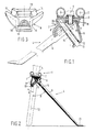
- FIG. 1 a part of a bicycle 1 is shown with a rear fork 2 and a support plate 3 welded thereto.
- a bicycle stand 4 according to the invention is mounted on the support plate 3 by means of a bolt 5.
- the bicycle stand 4 comprises a support leg 6, a housing 7, comprising a positioning member 8 and a bracket member 9.
- Mounted on the support leg 6 is a pin 10, extending in substantially transverse direction relative to that support leg 6.
- At terminal portions of the pin 10 suspensions 11 and 12 are formed by holes in the positioning member 8 and the bracket member 9, respectively, these holes mounting the pin 10 for rotation relative to the housing 7 and for displacement in its longitudinal direction.
- a helical spring 13 is arranged around the pin 10.
- positioning member 8 are positioning recesses 14 and 15 (see also Fig. 3).
- the spring 13 presses the support leg 6 and the pin 10 in the direction of the positioning recesses 14 and 15.
- the positioning member 8 is clamped in position between the bracket member 9 and the support plate 3.
- a threaded hole 16 for the bolt 5 to engage.
- the positioning member comprises a clamping surface 17 bounded by ribs 18 and 19 and an upright edge 20 surrounding the hole 11.
- a foot 21 Provided at the end of the stand that is remote from the housing 7.
- the support leg 6 exerts a moment on the bicycle 1, which prevents the bicycle from falling down. This moment is initiated by the support leg and transmitted via the pin 10 to the housing 7.
- the pin 10, extending substantially transverse to the support leg 6 may be of relatively great length in virtue of the fact that no elements disposed beyond the ends of that pin are connected to that pin. Owing to the relatively great length of the pin 10 the load on the suspensions 11 and 12 at the ends of the pin is relatively light, and, accordingly, these suspensions may be of light construction, can be loaded and/or will be wear-resistant.
- the angle A between the pin 10 and the longitudinal median plane 22 of the bicycle 1 defines the angle B between the plane of the pivotal movement of the support leg 6 and the longitudinal median plane 22 of the bicycle 1. According as angle B is greater, the angle A is smaller and the pin 10 to be mounted under the rear fork 2 may be of greater length. It is advantageous for the end of the pin which is proximal to the rear fork 2 to be bearing-mounted very closely to that rear fork.
- the positioning recesses 14, 15 which engage the support leg may be turned towards the inside of the housing 7. This eliminates the necessity of disposing any locking means on the outside of the housing. Such locking means harbour the risk of injury and of damage to clothes and limit the options as to the outward appearance of the housing 7.
- the support leg 6 is pressed into the direction of the positioning recesses 14 and 15 provided in the positioning member 8 by the spring 13 acting in the longitudinal direction of the pin 10 and is guided by the pin 10 adapted to be displaced in its longitudinal direction in the suspensions 11 and 12.
- the support leg When the support leg is moved to a point in front of one of the positioning recesses 14 or 15, the support leg will be locked in that positioning recess as a result of the action of the spring 13.
- the support leg 6 can thus be readily extended and retracted.
- Each of the housing members 8 and 9 mounts a terminal portion of the pin 10 and before being mounted on a bicycle the housing members 8 and 9 can each be slid over one of the terminal portions of the pin 10 in the axial direction of the pin 10 to abut the other housing member so as to form the housing 7.
- the bracket member 9 is drawn towards the rear fork 2 of the bicycle by means of the bolt 5, with the positioning member 8 being clamped therebetween.
- the positioning member is provided with a clamping surface 17 formed to correspond with the bracket member, which clamping surface 17 is bounded by the ribs 18 and 19 and the edge 20 surrounding the hole 11.
- the short end of the pin 10 can be mounted in the hole 11 in the housing 7. Then the spring 13 can be slid over the long end of the pin 10, and the pin 10 and the spring 13 can be locked by mounting the bracket member 9 over the pin 10 until it is in engagement with the surface 17. Counter to the force exerted by the spring 13, the bracket member 9 remains fixated relatively to the positioning member 8 and the pin 10, on account of the fact that the force exerted by the spring 13 on the bracket member 9 causes the bracket member 9 to tilt relatively to the positioning member 8, thus forcing the bracket member 9 into clamping engagement with the walls of the rib 18 and the edge 20 bounding the surface 17.
- the housing 7 can be assembled without separate attachment devices or tools, and in a very short time as well, since assembly comprises only single movements controlled by stops.
- the bracket member 9 preferably comprises a sharp edge 24 engaging said wall of the edge 20.
- the positioning recesses 14 and 15 are spaced away from the pin 10 on which the support leg 6 pivots, a relatively small force exerted by the positioning recesses on the support legs will yield a sufficiently strong locking of the support leg 6. Further, the supporting surfaces of the positioning recesses 14 and 15 can thus be formed to be sufficiently large to ensure that the pressure exerted on the positioning member is sufficiently low to allow that member to be made of plastic.
- Plastic design offers the advantage that the guide of the support leg 6 need not be lubricated and that the positioning member 8 may be formed as one whole, while at the same time it allows relatively great freedom as to the design of the upwardly turned side of the positioning member which is visible to the user.
- the plastic from which the housing 7 is to be made is preferably a polyacetal. This type of plastic which is processed by injection moulding has a low coefficient of friction when friction with metal is involved and is wear resistant.
- the distance over which the pin 10 extends into the mounting bore 11 is greater than the depth of the positioning recesses 14 and 15 relative to an edge 23 extending between these recesses 14 and 15.
- the pin 10 of a bicycle stand according to the invention for use in a conventional bicycle preferably has a length of at least 55 mm, and the distance between the suspensions 11 and 12 is preferably at least 35 mm.
- the support leg 6 of a bicycle stand according to the invention when in the extended position, can make a relatively great angle B with the longitudinal median plane 22 of the bicycle, the support leg 6 may have a relatively great length and rest on a support surface at a relatively great distance from the longitudinal median plane 22 of the bicycle 1, so that a relatively small surface pressure is exerted on that supporting surface.
- the support leg 6 may comprise a foot 21, so that the bicycle supported by the stand can be positioned on an even softer supporting surface without the support leg 6 penetrating into the soil and causing the bicycle to fall.
- the support leg 6 of the bicycle stand according to the invention can be designed to be so long that when the support leg 6 is retracted the foot 21 is disposed further back, clear of the path of the cyclist's foot.
Landscapes
- Engineering & Computer Science (AREA)
- Mechanical Engineering (AREA)
- Axle Suspensions And Sidecars For Cycles (AREA)
- Steering Devices For Bicycles And Motorcycles (AREA)
Applications Claiming Priority (2)
| Application Number | Priority Date | Filing Date | Title |
|---|---|---|---|
| NL8901894 | 1989-07-21 | ||
| NL8901894A NL8901894A (nl) | 1989-07-21 | 1989-07-21 | Fietsstandaard. |
Publications (2)
| Publication Number | Publication Date |
|---|---|
| EP0409352A1 true EP0409352A1 (fr) | 1991-01-23 |
| EP0409352B1 EP0409352B1 (fr) | 1994-03-09 |
Family
ID=19855084
Family Applications (1)
| Application Number | Title | Priority Date | Filing Date |
|---|---|---|---|
| EP19900201967 Expired - Lifetime EP0409352B1 (fr) | 1989-07-21 | 1990-07-20 | Support pour bicyclette |
Country Status (4)
| Country | Link |
|---|---|
| EP (1) | EP0409352B1 (fr) |
| DE (1) | DE69007191T2 (fr) |
| DK (1) | DK0409352T3 (fr) |
| NL (1) | NL8901894A (fr) |
Cited By (2)
| Publication number | Priority date | Publication date | Assignee | Title |
|---|---|---|---|---|
| EP1067042A1 (fr) * | 1999-07-08 | 2001-01-10 | Gebrüder Pletscher Ag | Support de roue arrière pour un véhicule à deux roues et deux-roues avec le support |
| EP2390169A1 (fr) | 2010-05-25 | 2011-11-30 | Koninklijke Gazelle B.V. | Béquille pour bicyclette |
Families Citing this family (2)
| Publication number | Priority date | Publication date | Assignee | Title |
|---|---|---|---|---|
| NL1021371C2 (nl) | 2002-09-01 | 2004-03-02 | Batavus Bv | Fiets-zijstandaard. |
| DE102011118725B4 (de) | 2011-11-16 | 2023-08-10 | Otmar Gutmann | Kopf einer Zweiradstütze mit Winkelveränderungsausgleich |
Citations (5)
| Publication number | Priority date | Publication date | Assignee | Title |
|---|---|---|---|---|
| CH166637A (fr) * | 1933-05-13 | 1934-01-15 | Mingarelli Lido | Dispositif de soutien pour cycles. |
| US2229551A (en) * | 1939-03-04 | 1941-01-21 | Cohen Berry | Bicycle stand |
| DE819200C (de) * | 1950-09-14 | 1951-10-31 | Willy Hartmann | Fahrradklappstuetze |
| GB1211088A (en) * | 1967-12-20 | 1970-11-04 | Herbert James Mccauley | Kickstand |
| FR2540816A1 (fr) * | 1983-02-15 | 1984-08-17 | Pletscher Geb | Bequille de bicyclette ou de motocyclette |
-
1989
- 1989-07-21 NL NL8901894A patent/NL8901894A/nl not_active Application Discontinuation
-
1990
- 1990-07-20 EP EP19900201967 patent/EP0409352B1/fr not_active Expired - Lifetime
- 1990-07-20 DK DK90201967T patent/DK0409352T3/da active
- 1990-07-20 DE DE1990607191 patent/DE69007191T2/de not_active Expired - Fee Related
Patent Citations (5)
| Publication number | Priority date | Publication date | Assignee | Title |
|---|---|---|---|---|
| CH166637A (fr) * | 1933-05-13 | 1934-01-15 | Mingarelli Lido | Dispositif de soutien pour cycles. |
| US2229551A (en) * | 1939-03-04 | 1941-01-21 | Cohen Berry | Bicycle stand |
| DE819200C (de) * | 1950-09-14 | 1951-10-31 | Willy Hartmann | Fahrradklappstuetze |
| GB1211088A (en) * | 1967-12-20 | 1970-11-04 | Herbert James Mccauley | Kickstand |
| FR2540816A1 (fr) * | 1983-02-15 | 1984-08-17 | Pletscher Geb | Bequille de bicyclette ou de motocyclette |
Cited By (2)
| Publication number | Priority date | Publication date | Assignee | Title |
|---|---|---|---|---|
| EP1067042A1 (fr) * | 1999-07-08 | 2001-01-10 | Gebrüder Pletscher Ag | Support de roue arrière pour un véhicule à deux roues et deux-roues avec le support |
| EP2390169A1 (fr) | 2010-05-25 | 2011-11-30 | Koninklijke Gazelle B.V. | Béquille pour bicyclette |
Also Published As
| Publication number | Publication date |
|---|---|
| DE69007191T2 (de) | 1994-09-01 |
| DK0409352T3 (da) | 1994-05-24 |
| DE69007191D1 (de) | 1994-04-14 |
| NL8901894A (nl) | 1991-02-18 |
| EP0409352B1 (fr) | 1994-03-09 |
Similar Documents
| Publication | Publication Date | Title |
|---|---|---|
| EP1884400B1 (fr) | Dispositif support pour siège de sécurité enfant dans une voiture | |
| US8157275B2 (en) | Collapsible skateboard | |
| US5419218A (en) | Safety pedal for bicycles and the like | |
| EP1122486B1 (fr) | Trepied | |
| US4919378A (en) | Support structure for bicycle saddle | |
| US20060230627A1 (en) | Tape measure mounting clip | |
| EP0409352B1 (fr) | Support pour bicyclette | |
| FR2645758A1 (fr) | Dispositif de fixation d'une chaussure a un ski de fond | |
| US6477917B1 (en) | Automatic cycle pedal | |
| FR2553672A1 (fr) | Machoire avant de securite pour fixation de ski | |
| JP2825493B2 (ja) | 自動起立式地雷 | |
| US5761967A (en) | Mounting frame of a vehicle control pedal unit | |
| EP1834866A2 (fr) | Dispositif de fixation, en particulier pour une fourche et une tige de support, pour monter des garde-boues de bicyclette | |
| EP2634074A1 (fr) | Agencement de support pour véhicule à deux roues | |
| US2735694A (en) | Bicycle kick stand mounting bracket | |
| FR2729721A1 (fr) | Dispositif de fixation a une paroi de support d'un element destine par exemple a porter des articles presentes dans un stand d'exposition | |
| US20030067137A1 (en) | Structure for fast removal of absorber for foldable bike | |
| FR2676083A1 (fr) | Dispositif de verrouillage d'un tiroir, poignee fixe de manóoeuvre, tiroir et meuble a tiroirs comprenant un tel dispositif. | |
| JPH09215541A (ja) | 引出しのラッチ装置 | |
| JP3645982B2 (ja) | キャビネット | |
| KR0131050Y1 (ko) | 프로젝터의 받침다리 | |
| US4571871A (en) | U-Shaped support and pivotal lever for fixing a barrel to the body of a firearm | |
| US2685452A (en) | Bicycle kick stand | |
| KR20210138339A (ko) | 낚시 받침대 | |
| EP4063245A1 (fr) | Support de vélo réglable |
Legal Events
| Date | Code | Title | Description |
|---|---|---|---|
| PUAI | Public reference made under article 153(3) epc to a published international application that has entered the european phase |
Free format text: ORIGINAL CODE: 0009012 |
|
| AK | Designated contracting states |
Kind code of ref document: A1 Designated state(s): BE DE DK FR GB LU NL |
|
| 17P | Request for examination filed |
Effective date: 19901220 |
|
| 17Q | First examination report despatched |
Effective date: 19921021 |
|
| GRAA | (expected) grant |
Free format text: ORIGINAL CODE: 0009210 |
|
| AK | Designated contracting states |
Kind code of ref document: B1 Designated state(s): BE DE DK FR GB LU NL |
|
| REF | Corresponds to: |
Ref document number: 69007191 Country of ref document: DE Date of ref document: 19940414 |
|
| REG | Reference to a national code |
Ref country code: DK Ref legal event code: T3 |
|
| ET | Fr: translation filed | ||
| EPTA | Lu: last paid annual fee | ||
| PLBE | No opposition filed within time limit |
Free format text: ORIGINAL CODE: 0009261 |
|
| STAA | Information on the status of an ep patent application or granted ep patent |
Free format text: STATUS: NO OPPOSITION FILED WITHIN TIME LIMIT |
|
| 26N | No opposition filed | ||
| PGFP | Annual fee paid to national office [announced via postgrant information from national office to epo] |
Ref country code: GB Payment date: 19990722 Year of fee payment: 10 |
|
| PGFP | Annual fee paid to national office [announced via postgrant information from national office to epo] |
Ref country code: LU Payment date: 19990729 Year of fee payment: 10 |
|
| PGFP | Annual fee paid to national office [announced via postgrant information from national office to epo] |
Ref country code: FR Payment date: 19990730 Year of fee payment: 10 |
|
| PG25 | Lapsed in a contracting state [announced via postgrant information from national office to epo] |
Ref country code: GB Free format text: LAPSE BECAUSE OF NON-PAYMENT OF DUE FEES Effective date: 20000720 Ref country code: LU Free format text: LAPSE BECAUSE OF NON-PAYMENT OF DUE FEES Effective date: 20000720 |
|
| GBPC | Gb: european patent ceased through non-payment of renewal fee |
Effective date: 20000720 |
|
| PG25 | Lapsed in a contracting state [announced via postgrant information from national office to epo] |
Ref country code: FR Free format text: LAPSE BECAUSE OF NON-PAYMENT OF DUE FEES Effective date: 20010330 |
|
| REG | Reference to a national code |
Ref country code: FR Ref legal event code: ST |
|
| PGFP | Annual fee paid to national office [announced via postgrant information from national office to epo] |
Ref country code: DK Payment date: 20070717 Year of fee payment: 18 |
|
| PGFP | Annual fee paid to national office [announced via postgrant information from national office to epo] |
Ref country code: DE Payment date: 20070908 Year of fee payment: 18 |
|
| PGFP | Annual fee paid to national office [announced via postgrant information from national office to epo] |
Ref country code: BE Payment date: 20070716 Year of fee payment: 18 Ref country code: NL Payment date: 20070717 Year of fee payment: 18 |
|
| REG | Reference to a national code |
Ref country code: DK Ref legal event code: EBP |
|
| NLV4 | Nl: lapsed or anulled due to non-payment of the annual fee |
Effective date: 20090201 |
|
| PG25 | Lapsed in a contracting state [announced via postgrant information from national office to epo] |
Ref country code: DE Free format text: LAPSE BECAUSE OF NON-PAYMENT OF DUE FEES Effective date: 20090203 |
|
| PG25 | Lapsed in a contracting state [announced via postgrant information from national office to epo] |
Ref country code: NL Free format text: LAPSE BECAUSE OF NON-PAYMENT OF DUE FEES Effective date: 20090201 |
|
| PG25 | Lapsed in a contracting state [announced via postgrant information from national office to epo] |
Ref country code: DK Free format text: LAPSE BECAUSE OF NON-PAYMENT OF DUE FEES Effective date: 20080731 |
|
| PG25 | Lapsed in a contracting state [announced via postgrant information from national office to epo] |
Ref country code: BE Free format text: LAPSE BECAUSE OF NON-PAYMENT OF DUE FEES Effective date: 20080731 |