EP0409395A1 - Protection anti-poussière pour un amortisseur - Google Patents
Protection anti-poussière pour un amortisseur Download PDFInfo
- Publication number
- EP0409395A1 EP0409395A1 EP90306081A EP90306081A EP0409395A1 EP 0409395 A1 EP0409395 A1 EP 0409395A1 EP 90306081 A EP90306081 A EP 90306081A EP 90306081 A EP90306081 A EP 90306081A EP 0409395 A1 EP0409395 A1 EP 0409395A1
- Authority
- EP
- European Patent Office
- Prior art keywords
- dust shield
- damper
- body portion
- rib
- bump plate
- Prior art date
- Legal status (The legal status is an assumption and is not a legal conclusion. Google has not performed a legal analysis and makes no representation as to the accuracy of the status listed.)
- Granted
Links
- 239000000428 dust Substances 0.000 title claims abstract description 81
- 230000006835 compression Effects 0.000 description 10
- 238000007906 compression Methods 0.000 description 10
- 230000000694 effects Effects 0.000 description 4
- 239000006096 absorbing agent Substances 0.000 description 3
- 230000035939 shock Effects 0.000 description 3
- 239000000356 contaminant Substances 0.000 description 2
- 239000012212 insulator Substances 0.000 description 2
- 239000012858 resilient material Substances 0.000 description 2
- 230000000717 retained effect Effects 0.000 description 2
- 239000000725 suspension Substances 0.000 description 2
- 230000000712 assembly Effects 0.000 description 1
- 238000000429 assembly Methods 0.000 description 1
- 238000000576 coating method Methods 0.000 description 1
- 230000003247 decreasing effect Effects 0.000 description 1
- 238000009434 installation Methods 0.000 description 1
- 230000014759 maintenance of location Effects 0.000 description 1
- 238000004904 shortening Methods 0.000 description 1
- 125000006850 spacer group Chemical group 0.000 description 1
Images

Classifications
-
- F—MECHANICAL ENGINEERING; LIGHTING; HEATING; WEAPONS; BLASTING
- F16—ENGINEERING ELEMENTS AND UNITS; GENERAL MEASURES FOR PRODUCING AND MAINTAINING EFFECTIVE FUNCTIONING OF MACHINES OR INSTALLATIONS; THERMAL INSULATION IN GENERAL
- F16F—SPRINGS; SHOCK-ABSORBERS; MEANS FOR DAMPING VIBRATION
- F16F9/00—Springs, vibration-dampers, shock-absorbers, or similarly-constructed movement-dampers using a fluid or the equivalent as damping medium
- F16F9/32—Details
- F16F9/38—Covers for protection or appearance
Definitions
- the present invention relates generally to a damper for a vehicle, and more particularly is directed to a dust shield for use with a damper as specified in the preamble of claim 1, for example as disclosed in US-A-4,529,213.
- Dampers e.g. shock absorbers or struts, for suspension systems in automobiles are well-known.
- dust shields In order to protect a damper and its seals from contaminants such as dirt, gravel, etc., dust shields have been utilized with dampers.
- a dust shield is a moulded member formed from rubber or similar resilient material and includes a hollow cylindrical body which is slipped over an upper end of a damper. The dust shield is retained about the damper in any suitable manner.
- Many dust shields include a portion of inner and outer convolutions on the outer surface of the dust shield. Such convolutions provide a spring-like effect by permitting the dust shield to be compressed when the damper is in compression and causing the dust shield to expand to its approximate original length during rebound of the damper.
- a coil spring surrounds the damper and its accompanying dust shield.
- the dust shield may shift from side to side about the longitudinal axis of the damper.
- the outer surface and its convolutions if any, can engage the coil spring, thereby causing excessive wear of the dust shield and wear of any coatings that may be provided on the coil spring.
- the inner surface and its convolutions, if any, can rub against the damper when the dust shield is shifted, thereby causing unwanted noise and excessive wear.
- a dust shield according to the present invention is characterised by the features specified in the characterising portion of claim 1.
- the present invention includes a dust shield for use with a damper.
- the dust shield is formed from a moulded tubular member and includes a plurality of convolutions to provide a spring-like effect in the dust shield.
- the dust shield includes a plurality of inwardly-projecting fingers having ribs which centre the dust shield on a damper. The centering ribs prevent the dust shield from substantial shifting during compression and rebound of the damper, thereby eliminating contact between the dust shield and a surrounding coil spring or a bump plate mounted on the damper. Furthermore, the ribs force the dust shield to expand to its approximate original length during rebound of the damper to provide full-time cover of a piston rod of the damper.
- the present dust shield can be utilized with conventional shock absorbers and struts.
- the present invention includes a dust shield for use with a damper.
- the dust shield includes a hollow cylindrical body having first and second ends. Convolutions are provided in the outer surface of the body between its ends. Inwardly-projecting fingers are provided in the body portion. Each finger includes a centering rib extending to the damper to prevent shifting of the dust shield, thereby eliminating contact between the dust shield and a surrounding coil spring or a bump plate mounted on the damper. Additionally, each finger includes a retaining wall. The bump plate engages the retaining wall during rebound of the damper to pull the dust shield to its approximate original length to provide full-time cover of a piston rod of the damper.
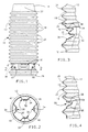
- the dust shield 10 includes a hollow cylindrical body 12 and a first, upper end 14 and a second, lower end 16.
- the dust shield 10 is formed as a moulded tubular member and includes a plurality of inner convolutions 18 and outer convolutions 20 on its outer surface which provide a spring-like effect for the body 12.
- the convolutions 18 and 20 permit the body 12 to yieldably compress and then expand to its approximate original length when the compression force is removed.
- the first end 14 includes a conical portion 22 having a central opening to receive a piston rod of a damper as described below.
- inwardly-projecting fingers 30 are provided in the outer surface of the body 12.
- four fingers 30 are equally spaced around the circumference of the body 12.
- various numbers of fingers 30 can be provided.
- each finger 30 is moulded into the body 12.
- Each finger 30 includes a first, centering rib 32 and a second, retaining rib 34 as illustrated best in Figure 3.
- the centering rib 32 projects inwardly towards the longitudinal axis of the body 12 a greater distance than the inward projection of the retaining rib 34 and engages a damper as described below.
- an angled ramp 36 connects the outer surface of the body 12 with the centering rib 32.
- a retaining wall 38 oriented approximately perpendicular to the longitudinal axis of the body 12 connects the retaining rib 34 to the outer surface of the body 12 opposite the ramp 36.
- a substantially C-shaped connecting wall 39 connects the centering rib 32 with the retaining rib 34.
- vents 40 can be provided on the outer surface of the body 12 interspaced between the fingers 30. Vents 40 can be provided by any suitable means. As described below, vents 40 permit the passage of air as the body 12 is compressed and expanded.
- the body 12 includes a plurality of inwardly-projecting fingers 50 provided in the outer circumference of the body 12 having only a first, retaining rib 54 which engages a damper as described below.
- a first, retaining rib 54 which engages a damper as described below.
- an angled ramp 56 connects the outer surface of the body 12 with the lower portion of each rib 54.
- a retaining wall 58 oriented approximately perpendicular to the longitudinal axis of the body 12 connects the upper portion of each rib 54 to the outer surface of the body 12 opposite the ramp 56.
- Damper assembly 100 can comprise a shock absorber or strut and includes a telescoping piston rod 102 received into an upper end of a reservoir tube 104 in a well-known manner.
- a piston assembly (not illustrated) is mounted on the piston rod 102 and reciprocates internally within the reservoir tube 104.
- the lower end of the reservoir tube 104 is received in a bracket 106 and is connected to a support structure of an automobile.
- the upper end of the piston rod 102 is retained in a mount assembly 108 by a nut 110.
- Fasteners 112 provide for connection of the mount assembly 108 to a support structure in a vehicle in a well-known manner.
- a coil spring 114 is seated at its upper end at an upper spring seat 116.
- a bearing 120 can be provided between the mount assembly 108 and the upper spring seat 116 to provide for rotation of the damper assembly 100 if desired.
- a spacer 122 and an insulator 124 can be inserted between the coil spring 114 and the upper spring seat 116.
- the lower portion of the coil spring 114 is seated on a lower spring seat 126.
- an insulator 128 can be provided between the coil spring 114 and the lower spring seat 126.
- a disk-like bump plate 130 having a central opening for receiving the piston rod 102 is mounted on an upper end of the reservoir tube 104.
- the diameter of the bump plate 130 is less than the diameter of the inner convolutions 18 of the dust shield 10.
- a jounce bumper 132 formed from a resilient material such as rubber is provided at an upper end of the piston rod 102.
- the second end 16 of the dust shield 10 is inserted over the piston rod 102 and forced past the bump plate 130 and onto the reservoir tube 104 until the fingers 30 are positioned below the bump plate 130.
- Ramps 36 facilitate the passage of the fingers 30 past the bump plate 130.
- the first end 14 of the dust shield 10 is secured at the upper end of the jounce bumper 132 in any conventional manner.
- each retaining wall 38 is approximately parallel with a lower surface of the bump plate 130.
- damper assembly 100 compresses as the piston rod 102 is received in the reservoir tube 104.
- the convolutions 18 and 20 permit the dust shield 10 to be resiliently compressed.
- the reservoir tube 104 and the attached lower spring seat 126 will move upwardly toward the upper spring seat 116.
- the convolutions 18 and 20 permit the compression of the body 12.
- the lower surface of the bump plate 130 engages the retaining walls 38 thereby pulling the second end 16 downwardly so that the dust shield 10 expands to its approximate original length.
- vents 40 permit the passage of air into the area between the dust shield 10 and the damper assembly 100 as the dust shield 10 expands.
- the centering ribs 32 project inwardly and engage the reservoir tube 104 to centre the lower end 16 of the dust shield 10 about the reservoir tube 104.
- the centering ribs 32 engage the reservoir tube 104 below a rough weld area 134 on the outer surface of the reservoir tube 104 to avoid accelerated wear of the ribs 32.
- a dust shield having fingers 50 with a single rib 54 ( Figure 4) will provide both the retaining and centering functions described above. Centering the dust shield 10 during use eliminates contact between the outer convolutions 20 and the spring 114, as well as contact between the inner convolutions 18 and the bump plate 130.
- the present dust shield 10 having a plurality of retaining fingers 30 or 50 provides continuous cover of the piston rod 102 during compression and rebound of the damper assembly 100.
- the fingers 30 or 50 centre the dust shield 10 on the damper assembly 100 to eliminate contact between the dust shield 10 and the spring 114 and the dust shield 10 and the bump plate 130.
Landscapes
- Engineering & Computer Science (AREA)
- General Engineering & Computer Science (AREA)
- Mechanical Engineering (AREA)
- Fluid-Damping Devices (AREA)
Applications Claiming Priority (2)
| Application Number | Priority Date | Filing Date | Title |
|---|---|---|---|
| US380244 | 1989-07-17 | ||
| US07/380,244 US4969542A (en) | 1989-07-17 | 1989-07-17 | Dust shield for a damper |
Publications (2)
| Publication Number | Publication Date |
|---|---|
| EP0409395A1 true EP0409395A1 (fr) | 1991-01-23 |
| EP0409395B1 EP0409395B1 (fr) | 1994-05-04 |
Family
ID=23500442
Family Applications (1)
| Application Number | Title | Priority Date | Filing Date |
|---|---|---|---|
| EP90306081A Expired - Lifetime EP0409395B1 (fr) | 1989-07-17 | 1990-06-05 | Protection anti-poussière pour un amortisseur |
Country Status (5)
| Country | Link |
|---|---|
| US (1) | US4969542A (fr) |
| EP (1) | EP0409395B1 (fr) |
| JP (1) | JPH0356736A (fr) |
| DE (1) | DE69008632T2 (fr) |
| ES (1) | ES2052177T3 (fr) |
Cited By (4)
| Publication number | Priority date | Publication date | Assignee | Title |
|---|---|---|---|---|
| FR2660719A1 (fr) * | 1990-04-09 | 1991-10-11 | Fichtel & Sachs Ag | Element amortisseur de choc. |
| DE4233319A1 (de) * | 1992-10-05 | 1994-04-07 | Continental Ag | Hohlkörper, insbesondere Schutzbalg für die Kolbenstange eines Stoßdämpfers |
| KR20020028671A (ko) * | 2000-10-11 | 2002-04-17 | 밍 루 | 쇽 업소버의 더스트 커버 |
| DE102018218509A1 (de) * | 2018-10-29 | 2020-04-30 | Volkswagen Aktiengesellschaft | Stoßdämpfer für ein Kraftfahrzeug und Schutzrohr für einen solchen |
Families Citing this family (20)
| Publication number | Priority date | Publication date | Assignee | Title |
|---|---|---|---|---|
| DE4137447C2 (de) * | 1990-11-26 | 2003-08-21 | Volkswagen Ag | Teleskopstoßdämpfer |
| US5275389A (en) * | 1991-10-23 | 1994-01-04 | Saturn Corporation | Jounce bumper and dust shield subassembly for a suspension damper |
| DE4139131A1 (de) * | 1991-11-28 | 1993-06-03 | Fichtel & Sachs Ag | Schutzeinrichtung fuer die kolbenstange eines schwingungsdaempfers |
| JP3205480B2 (ja) * | 1995-03-23 | 2001-09-04 | 東海ゴム工業株式会社 | サスペンション装置 |
| US5901947A (en) * | 1995-06-07 | 1999-05-11 | North American Parts Distributors Inc. | One piece bumper-bellows subassembly |
| US5671500A (en) * | 1995-08-07 | 1997-09-30 | Balk; Brett | Overhead door spring shield system |
| US5954168A (en) * | 1997-05-28 | 1999-09-21 | American Showa, Inc. | Dust cover for shock absorber and method of manufacturing the same |
| US6199844B1 (en) | 1998-07-27 | 2001-03-13 | Chrysler Corporation | Striker cap for vehicle suspension system |
| DE50002439D1 (de) * | 1999-09-17 | 2003-07-10 | Phoenix Ag | Luftfederanordnung |
| KR101202728B1 (ko) * | 2004-07-15 | 2012-11-19 | 젯트에프 프리드리히스하펜 아게 | 유압, 유공압 또는 공압 피스톤-실린더-집합체 및 이를 위한 주름 연결부 |
| US7445202B2 (en) * | 2004-11-12 | 2008-11-04 | Honda Motor Co., Ltd. | Shield assembly for a vehicle suspension |
| US20070181392A1 (en) * | 2006-02-07 | 2007-08-09 | Toyota Engineering & Manufacturing North America, Inc. | Gas strut protective cover |
| JP4909604B2 (ja) * | 2006-02-13 | 2012-04-04 | カヤバ工業株式会社 | ダストブーツ |
| KR101371760B1 (ko) * | 2012-12-21 | 2014-03-07 | 현대자동차(주) | 쇼크업소버장치 |
| JP5924422B2 (ja) * | 2012-12-26 | 2016-05-25 | トヨタ自動車株式会社 | 車両用サスペンション装置及び車両用サスペンション装置の組立方法 |
| JP5613280B2 (ja) * | 2013-03-22 | 2014-10-22 | 東海ゴム工業株式会社 | ダストカバー |
| WO2016079685A1 (fr) * | 2014-11-20 | 2016-05-26 | Taplast S.P.A. | Élément élastique pour dispositif pour la distribution de fluides ou de mélanges et procédé et moule pour la fabrication dudit élément élastique |
| US20160298763A1 (en) * | 2015-04-09 | 2016-10-13 | Bendix Commercial Vehicle Systems Llc | Piston assembly for an unloader valve of an air compressor |
| KR102718861B1 (ko) * | 2015-11-24 | 2024-10-18 | 엔브이비 프러펄션 인터내셔널 리미티드 | 피스톤-챔버 조합체 |
| JP6714368B2 (ja) * | 2016-01-26 | 2020-06-24 | 住友理工株式会社 | ダストカバー |
Citations (6)
| Publication number | Priority date | Publication date | Assignee | Title |
|---|---|---|---|---|
| DE1750052A1 (de) * | 1967-08-17 | 1971-03-11 | Claude Ralet | An einem Ende geschlossene Balgmembran aus Kunststoff als deformierbarer Schutz gegen ein unter Druck stehendes fluessiges oder gasfoermiges Medium |
| FR2163081A5 (fr) * | 1971-11-24 | 1973-07-20 | Westinghouse Bremsen | |
| US3907080A (en) * | 1971-02-25 | 1975-09-23 | Gen Motors Corp | Telescopic shock absorber and dust shield |
| US4235426A (en) * | 1979-04-11 | 1980-11-25 | General Motors Corporation | Shock absorber with compression spring and dust tube |
| US4529213A (en) * | 1983-09-12 | 1985-07-16 | Daystar, Inc. | Boot structure |
| GB2166815A (en) * | 1984-10-31 | 1986-05-14 | Tokai Trw & Co | Bellows to enclose pivotting joint |
Family Cites Families (7)
| Publication number | Priority date | Publication date | Assignee | Title |
|---|---|---|---|---|
| US2708112A (en) * | 1951-10-16 | 1955-05-10 | Dunlop Rubber Co | Shock absorbers |
| DE1902019A1 (de) * | 1969-01-16 | 1970-08-06 | Fichtel & Sachs Ag | Kunststoffschutzrohr fuer Schwingungsdaempfer,Federungen od.dgl. |
| GB1323194A (en) * | 1971-02-25 | 1973-07-11 | Gen Motors Ltd | Telescopic shock absorbers |
| US4114460A (en) * | 1977-02-24 | 1978-09-19 | Roto Manufacturing Co., Inc. | Protective boot |
| EP0105232B1 (fr) * | 1982-09-14 | 1986-12-10 | Nissan Motor Co., Ltd. | Jambe de suspension pour un véhicule automobile |
| US4462608A (en) * | 1983-09-01 | 1984-07-31 | General Motors Corporation | Steerable suspension bearing assembly |
| US4771996A (en) * | 1987-03-26 | 1988-09-20 | Maremont Corporation | MacPherson strut with floating striker plate |
-
1989
- 1989-07-17 US US07/380,244 patent/US4969542A/en not_active Expired - Lifetime
-
1990
- 1990-06-05 ES ES90306081T patent/ES2052177T3/es not_active Expired - Lifetime
- 1990-06-05 DE DE69008632T patent/DE69008632T2/de not_active Expired - Fee Related
- 1990-06-05 EP EP90306081A patent/EP0409395B1/fr not_active Expired - Lifetime
- 1990-07-16 JP JP2185472A patent/JPH0356736A/ja active Pending
Patent Citations (6)
| Publication number | Priority date | Publication date | Assignee | Title |
|---|---|---|---|---|
| DE1750052A1 (de) * | 1967-08-17 | 1971-03-11 | Claude Ralet | An einem Ende geschlossene Balgmembran aus Kunststoff als deformierbarer Schutz gegen ein unter Druck stehendes fluessiges oder gasfoermiges Medium |
| US3907080A (en) * | 1971-02-25 | 1975-09-23 | Gen Motors Corp | Telescopic shock absorber and dust shield |
| FR2163081A5 (fr) * | 1971-11-24 | 1973-07-20 | Westinghouse Bremsen | |
| US4235426A (en) * | 1979-04-11 | 1980-11-25 | General Motors Corporation | Shock absorber with compression spring and dust tube |
| US4529213A (en) * | 1983-09-12 | 1985-07-16 | Daystar, Inc. | Boot structure |
| GB2166815A (en) * | 1984-10-31 | 1986-05-14 | Tokai Trw & Co | Bellows to enclose pivotting joint |
Cited By (5)
| Publication number | Priority date | Publication date | Assignee | Title |
|---|---|---|---|---|
| FR2660719A1 (fr) * | 1990-04-09 | 1991-10-11 | Fichtel & Sachs Ag | Element amortisseur de choc. |
| DE4233319A1 (de) * | 1992-10-05 | 1994-04-07 | Continental Ag | Hohlkörper, insbesondere Schutzbalg für die Kolbenstange eines Stoßdämpfers |
| KR20020028671A (ko) * | 2000-10-11 | 2002-04-17 | 밍 루 | 쇽 업소버의 더스트 커버 |
| DE102018218509A1 (de) * | 2018-10-29 | 2020-04-30 | Volkswagen Aktiengesellschaft | Stoßdämpfer für ein Kraftfahrzeug und Schutzrohr für einen solchen |
| DE102018218509B4 (de) | 2018-10-29 | 2026-04-16 | Volkswagen Aktiengesellschaft | Stoßdämpfer für ein Kraftfahrzeug und Schutzrohr für einen solchen |
Also Published As
| Publication number | Publication date |
|---|---|
| ES2052177T3 (es) | 1994-07-01 |
| US4969542A (en) | 1990-11-13 |
| EP0409395B1 (fr) | 1994-05-04 |
| JPH0356736A (ja) | 1991-03-12 |
| DE69008632T2 (de) | 1994-08-18 |
| DE69008632D1 (de) | 1994-06-09 |
Similar Documents
| Publication | Publication Date | Title |
|---|---|---|
| EP0409395B1 (fr) | Protection anti-poussière pour un amortisseur | |
| US5275389A (en) | Jounce bumper and dust shield subassembly for a suspension damper | |
| EP0282144B1 (fr) | Dispositif de montage rapide pour jambe de suspension | |
| US5487535A (en) | Suspension strut metal-to-metal jounce stop | |
| US5248134A (en) | Snap-in upper mount assembly and method of use | |
| EP0249369B1 (fr) | Jambe de suspension de véhicule comprenant une attache supérieure | |
| US4805886A (en) | Jounce bumper assembly for vehicle suspension strut | |
| US5467970A (en) | Vehicle suspension system with jounce bumper | |
| US4256292A (en) | Jounce bumper for suspensions | |
| US5342029A (en) | Suspension strut upper mount | |
| EP0253261B1 (fr) | Système de suspension à ressort pneumatique | |
| US4274655A (en) | Resilient mount for MacPherson strut | |
| EP1393936B1 (fr) | Ensemble de montage supérieure pour un amortisseur de suspension | |
| US4248454A (en) | Suspension strut isolator mount | |
| JP2795414B2 (ja) | コンビネーシヨン・アイソレーター・マウントと空気バネ閉鎖を含む車両用懸架システム | |
| EP0105232A1 (fr) | Jambe de suspension pour un véhicule automobile | |
| JPH0743508Y2 (ja) | 懸架装置におけるアッパサポート | |
| US6182953B1 (en) | Spring and strut module with restraint for strut bumper | |
| US4958849A (en) | Mounting assembly and method for a damper | |
| EP0318696A2 (fr) | Sustension à ressort à air avec isolation à deux voies | |
| US4747587A (en) | Low profile suspension strut | |
| EP0479548A1 (fr) | Support amortissant les chocs | |
| EP0588620A1 (fr) | Butées de débattement | |
| GB2158549A (en) | Suspension strut mounting for motor vehicles | |
| US5775720A (en) | Shock absorbing apparatus |
Legal Events
| Date | Code | Title | Description |
|---|---|---|---|
| PUAI | Public reference made under article 153(3) epc to a published international application that has entered the european phase |
Free format text: ORIGINAL CODE: 0009012 |
|
| AK | Designated contracting states |
Kind code of ref document: A1 Designated state(s): DE ES FR GB |
|
| 17P | Request for examination filed |
Effective date: 19910207 |
|
| 17Q | First examination report despatched |
Effective date: 19930205 |
|
| GRAA | (expected) grant |
Free format text: ORIGINAL CODE: 0009210 |
|
| AK | Designated contracting states |
Kind code of ref document: B1 Designated state(s): DE ES FR GB |
|
| PG25 | Lapsed in a contracting state [announced via postgrant information from national office to epo] |
Ref country code: ES Free format text: LAPSE BECAUSE OF EXPIRATION OF PROTECTION Effective date: 19940606 |
|
| REF | Corresponds to: |
Ref document number: 69008632 Country of ref document: DE Date of ref document: 19940609 |
|
| ET | Fr: translation filed | ||
| REG | Reference to a national code |
Ref country code: ES Ref legal event code: FG2A Ref document number: 2052177 Country of ref document: ES Kind code of ref document: T3 |
|
| PLBE | No opposition filed within time limit |
Free format text: ORIGINAL CODE: 0009261 |
|
| STAA | Information on the status of an ep patent application or granted ep patent |
Free format text: STATUS: NO OPPOSITION FILED WITHIN TIME LIMIT |
|
| 26N | No opposition filed | ||
| PGFP | Annual fee paid to national office [announced via postgrant information from national office to epo] |
Ref country code: GB Payment date: 19970602 Year of fee payment: 8 |
|
| PGFP | Annual fee paid to national office [announced via postgrant information from national office to epo] |
Ref country code: FR Payment date: 19970627 Year of fee payment: 8 |
|
| PGFP | Annual fee paid to national office [announced via postgrant information from national office to epo] |
Ref country code: DE Payment date: 19970725 Year of fee payment: 8 |
|
| PG25 | Lapsed in a contracting state [announced via postgrant information from national office to epo] |
Ref country code: GB Free format text: LAPSE BECAUSE OF NON-PAYMENT OF DUE FEES Effective date: 19980605 |
|
| GBPC | Gb: european patent ceased through non-payment of renewal fee |
Effective date: 19980605 |
|
| PG25 | Lapsed in a contracting state [announced via postgrant information from national office to epo] |
Ref country code: FR Free format text: LAPSE BECAUSE OF NON-PAYMENT OF DUE FEES Effective date: 19990226 |
|
| PG25 | Lapsed in a contracting state [announced via postgrant information from national office to epo] |
Ref country code: DE Free format text: LAPSE BECAUSE OF NON-PAYMENT OF DUE FEES Effective date: 19990401 |
|
| REG | Reference to a national code |
Ref country code: FR Ref legal event code: ST |
|
| REG | Reference to a national code |
Ref country code: ES Ref legal event code: FD2A Effective date: 20010601 |