EP0410018A1 - Procédé et dispositif pour le remplissage automatique d'une tête d'avivage avec un agent mouillant pour une broche à retordre à double torsion - Google Patents
Procédé et dispositif pour le remplissage automatique d'une tête d'avivage avec un agent mouillant pour une broche à retordre à double torsion Download PDFInfo
- Publication number
- EP0410018A1 EP0410018A1 EP89113548A EP89113548A EP0410018A1 EP 0410018 A1 EP0410018 A1 EP 0410018A1 EP 89113548 A EP89113548 A EP 89113548A EP 89113548 A EP89113548 A EP 89113548A EP 0410018 A1 EP0410018 A1 EP 0410018A1
- Authority
- EP
- European Patent Office
- Prior art keywords
- head
- adapter
- double
- storage container
- wetting agent
- Prior art date
- Legal status (The legal status is an assumption and is not a legal conclusion. Google has not performed a legal analysis and makes no representation as to the accuracy of the status listed.)
- Granted
Links
- 239000000080 wetting agent Substances 0.000 title claims abstract description 21
- 238000000034 method Methods 0.000 title description 4
- 238000012423 maintenance Methods 0.000 claims abstract description 28
- 238000011017 operating method Methods 0.000 claims abstract 3
- 239000000945 filler Substances 0.000 claims description 14
- 238000009736 wetting Methods 0.000 claims description 3
- 239000011148 porous material Substances 0.000 claims description 2
- 230000000295 complement effect Effects 0.000 claims 1
- 230000000694 effects Effects 0.000 claims 1
- 239000007788 liquid Substances 0.000 description 2
- 238000003825 pressing Methods 0.000 description 2
- 239000003795 chemical substances by application Substances 0.000 description 1
- 230000006835 compression Effects 0.000 description 1
- 238000007906 compression Methods 0.000 description 1
- 230000003750 conditioning effect Effects 0.000 description 1
- 238000010276 construction Methods 0.000 description 1
- 238000005516 engineering process Methods 0.000 description 1
- 239000000314 lubricant Substances 0.000 description 1
- 230000001681 protective effect Effects 0.000 description 1
- 238000004804 winding Methods 0.000 description 1
Images

Classifications
-
- D—TEXTILES; PAPER
- D01—NATURAL OR MAN-MADE THREADS OR FIBRES; SPINNING
- D01H—SPINNING OR TWISTING
- D01H13/00—Other common constructional features, details or accessories
- D01H13/005—Service carriages travelling along the machines
-
- D—TEXTILES; PAPER
- D01—NATURAL OR MAN-MADE THREADS OR FIBRES; SPINNING
- D01H—SPINNING OR TWISTING
- D01H13/00—Other common constructional features, details or accessories
- D01H13/30—Moistening, sizing, oiling, waxing, colouring, or drying yarns or the like as incidental measures during spinning or twisting
- D01H13/302—Moistening, e.g. for wet spinning
Definitions
- Double-wire twisting spindles are often provided with thread wetting devices in the form of an Aviva head which can be plugged onto the hollow spindle axis with the interposition of a coil adapter and which has a storage container filled with a wetting agent and a porous net body with capillary action, along which the thread brushes to remove the wetting agent Net body is supplied from below by suction from the storage container.
- the object of the invention is to refuel the storage container of the aviva head in an automated working process with new wetting agent.
- the method dealt with in claim 2 is characterized in that this refueling of the aviva head is carried out in connection with the exchange of empty bobbin tubes for fully wound template or cross-wound bobbins.
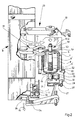
- FIG. 1 shows a detail of a double-wire twisting machine A, an automatic maintenance machine B which can be moved along the double-wire twisting machine on lower and upper rails 1 and 2, and a hanging conveyor device C.
- the overhead conveyor device C comprises a top rail 3, in which a conveyor chain or a conveyor belt is guided, to which or on which bobbin hanging holders 4 for bobbin adapters or bobbin transport adapters 5, which hang down at regular intervals, are fastened.
- the bobbin hanging holder 4 and the bobbin adapter 5 are designed in a known manner so that when a bobbin adapter 5 is started up, the bobbin adapter is gripped and held by the bobbin hanging holder, while the bobbin adapter 5 is released by the bobbin hanging holder 4 during the subsequent raising and lowering thereof.
- FIG. 1 shows in the area of the top rail 3 on the left side six bobbin adapters 5 each equipped with two fully wound cross-wound bobbins 6, which are to be transferred to the individual twisting points of the double-wire twisting machine 1 by means of the maintenance machine B, and two with empty sleeves 6 on the right 'Equipped coil adapter 5, which from the maintenance machine B have been taken individually from twisting points of the double-wire twisting machine A and transferred to a bobbin hanging holder 4.
- the double-wire twisting machine A comprises several working or twisting stations with the usual known elements such as (not shown) spindle in the lower area, balloon limiter 7, bobbin pot 8, thread inlet 9, balloon thread guide 10, deflection elements 11 for controlling the thread opening tension, advance line 12, traversing thread guide 13 and the cross-wound spool or take-up spool 15 driven by a friction roller 14.
- a conveyor belt 16 in the upper area between the two parallel longitudinal machine sides for the removal of fully wound cross-wound bobbins 15.
- the package 15 has a sleeve magazine 17 for empty take-up tubes 18.
- FIG. 1 shows schematically and in sections various handling elements of the machine B, which are used to replace a bobbin adapter 5 (drain unit) equipped with empty bobbin tubes 6 'with a full bobbin 6 Equipped bobbin adapter 5 (template unit) and for manipulating or securing the thread ends of the empty or almost unwound bobbin tubes 6 '.
- a bobbin adapter 5 drain unit
- empty bobbin tubes 6 ' with empty bobbin tubes 6 Equipped bobbin adapter 5 (template unit) and for manipulating or securing the thread ends of the empty or almost unwound bobbin tubes 6 '.
- These are mainly two holding mandrels 100, which can be pivoted about a vertical axis and can be moved up and down in the vertical direction, for supply and discharge units as well as gripper and suction devices 22 and 23.
- the maintenance machine B has a cabinet-shaped housing 101, the front wall of which is provided with a guide slot 102 for the pivotable cross arm 103 carrying a mandrel 100.
- the bobbin adapter 5 which is also a transport adapter in the manner described above, consists of a cylinder section 5.1 which has a supporting flange 5.2 at its lower end and Area of its upper end preferably has an annular groove 5.3.
- To Removal of the drain unit from the double-wire twisting spindle is used for the lower gripper 22 of the maintenance machine B, which has the two gripper arms 22.1 and 22.2 and can be pivoted in the horizontal direction (arrows f1), and is movable up and down.
- the gripper ends of the two gripper arms 22.1 and 22.2 can be used in the bobbin 8 inserted bobbin adapter 5 on its outer circumference, but preferably in the area of its annular groove 5.3, tightly enclosing, which at the same time the end of the not yet fully expired lower bobbin tube 6 'coming into the hollow core of the bobbin adapter is automatically clamped and secured.
- the bobbin adapter 5 is removed from the bobbin 8 by raising the gripper 22, care must be taken to ensure that the thread end of the thread end is pulled out of the hollow axis of the spindle without any hindrance by automatically opening a thread brake arranged in a known manner inside the spindle hollow axis of the double-wire twisting spindle can.
- a two-part coil adapter is assumed.
- the lower section of the adapter represents a means of transport for the fully wound bobbins or the expired tubes. In this form, it is also part of the bobbin transport system that is superior to the double-wire twisting machine. On the double wire twisting spindle, i.e. Within the bobbin, such an adapter lower part also serves to center the bobbins on the hub of the bobbin.
- this adapter lower part 5 is a hollow Axial head part or adapter upper part 50 plugged on, which serves in a known manner to create different thread run-off conditions on a double-wire twisting spindle.
- This adapter upper part is an aviva head 50 forming a thread inlet for wetting the continuous thread with an avivating agent.
- this aviva head 50 consists of an annular storage container 51, the top of which is closed, optionally by means of a removable lid.
- a central tube 52 is guided through the bottom of the storage container 51 and, with its end projecting downward from the storage container 51, can be inserted into the hollow axis of the lower bobbin adapter 5 within a double-wire twisted spindle in the extension of the hollow spindle axis, as can be seen in FIG 3 results.
- the top or the lid of the storage container 51 is provided with an outwardly directed central tube extension 51.1, into which a net body 53 in the form of an annular, rigid rotational body made of porous material with a capillary action is inserted.
- the surface of the net body 53 facing the thread has an inwardly directed, spherical surface.
- the lower portion of the tubular net body is pushed onto the part of the central tube 52 located within the storage container 51.
- Lubricant or wetting agent 54 filled into the storage container 51 is conveyed upwards under the influence of the capillary action as long as the porous net body 53 is immersed in this wetting agent, so that threads sliding along the crowned surface of the net body 53 are wetted with the wetting agent.
- the supply of wetting agent within the storage container 51 is used up, so that wetting agent must be refilled from time to time.
- the storage container 51 is provided with an internal refueling chamber 55 which has an opening 55.1 on its upper side and a downwardly directed cylindrical bore 55.2 in its bottom, which merges into a conical opening 55.3 which widens outwards.
- a valve body 56 carrying an annular seal 57 is inserted into the cylinder bore 55.2 and is slidably guided in the cylinder bore 55.2 with its hollow cylindrical shaft 56.1 projecting downwards.
- the hollow cylindrical shaft is provided with lateral openings 56.2 in the area of its upper end.
- the valve body 56 is under the force of a return and closing spring 58 which is supported on the upper side of the refueling chamber 55 and by which the valve body 56 is loaded in such a way that it rests with its ring seal 57 against the bottom of the refueling chamber 55 forming a valve seat.
- An annular lip seal 59 is inserted into the cone opening 55.3.
- the upper cover wall or the cover of the storage container 51 is provided with a blind bore 60 of larger diameter, which is closed by a stopper 61, to which a passage bore 62 of smaller diameter leading into the interior of the chamber connects.
- a transverse bore 63 opens into the blind bore 60.
- the through bore 62 is at its upper end by an annular shoulder surrounded on which a valve flap 64 rests.
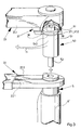
- Fig. 2 shows a portion of the double wire twisting machine in cross section, namely the machine frame 27, a compressed air line 28 with a connection leading to a double wire twisting spindle 29, which leads to a compressed air nozzle 30 for the pneumatic threading, and a spindle whorl 31 with belt pressure roller 32 for pressing a tangential drive belt 33 against the spindle whorl 31.
- a foot lever 34 assigned to each individual spindle serves to actuate a spindle brake (not shown), and this foot lever 34 also serves to actuate the compressed air nozzle 30 in order, in a known manner, to produce a suction air flow in the spindle hollow axis Build up thread threading through the spindle.
- FIG. 2 further shows part of the maintenance machine B patrolling in front of the double-wire twisting machine along the rails 1 and 2, of which maintenance and handling elements relevant for further description are shown in detail, such as the grippers 22 and 37 and the suction device 23, and a Actuating lever 35, by pressing it down in the direction of arrow f6, the foot lever 34 can be actuated at a given moment to stop the individual spindles.
- 2 shows just above the foot lever 34 two rollers 36 of the maintenance machine B, which are guided along a guide surface 1.1 of the lower rail 1.
- the suction device 23 with the upper gripper 37 is attached to a swivel arm 23.1 and is as well as the gripper 22 can be pivoted in the direction of arrow f1 and can be moved up and down in the direction of arrow f5 in the vertical direction.
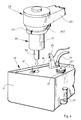
- Fig. 3 shows the lower gripper 22 as it grips the adapter lower part 5 with its two gripper arms 22.1 and 22.2 and at the same time clamps the thread 6 'leading to the sleeve 6 which still has a residual winding.
- the aviva head 50 is gripped and held by the upper gripper 37 attached to the suction device 23, which has two gripper arms 37.1, 37.2 which can be pivoted in the horizontal direction.
- the gripper arms 37.1, 37.2 of the upper gripper 37 are provided with inwardly directed projections or lugs 38 which, when the gripper arms are closed, engage point-wise in an annular groove 51.2 of the aviva head 50. This ensures that a thread that runs along the outside of the aviva head 50 and runs into the center or the hollow axis of the aviva head at the top is not clamped by these gripper arms 37.1 or 37.2.
- Air lines are integrated in the lower gripper 22 or in its gripper arms 22.1 and 22.2 and in the suction device 23, through which either for the pneumatic actuation of the gripper arms or cutting devices, not shown, can be supplied with compressed air, or in which a suction air flow can be built up in order to suck off cut thread ends.
- the suction device 23 is pivoted laterally together with the upper gripper 37. Then the adapter lower part 5 can be lifted out of the coil pot 8 together with the two sleeves 6 'by means of the gripper 22. The gripper 22 is then pivoted so far into the maintenance machine B that the adapter lower part 5 with the two sleeves 6 'can be attached to one of the two mandrels 100, which has been brought into a corresponding pivot position.
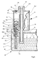
- the avivagehead 50 held by the gripper 37 is pivoted into the maintenance machine B into a position above the refueling station 40, see FIG. 4.
- the refueling station 40 contains part of the maintenance machine B forming storage tank 41 for wetting agent 54.
- This storage tank 41 has a liquid level indicator 42, a filler neck 43 which can be closed by means of a cover 43.1, a compressed air connection 44, a sensor 45 for determining the liquid level in the storage tank 41, a receptacle 46 for inserting the bottom from the Storage container projecting section of the pipe socket 52 of the Avivagekopf 50 and a filler neck 47 protruding upward from the storage tank 41.
- a pipe socket 48 which ends at the bottom open end above the tank bottom and opens at its upper end into a valve chamber 49, which is arranged below the upper cover wall of the storage tank 41 and via a bore 49.1 with the outside atmosphere in Connection is established.
- the tubular filler neck 47 projecting upward from the storage tank 41 is sealingly guided and carries at its end inside the valve chamber 49 a valve disk 47.1 with an annular seal 47.2. Lateral openings are arranged in the filler neck 47 directly above the valve plate 47.1.
- a closing or return spring 47.3 acts on the valve plate 47.1, from which the valve plate or the valve plate ring seal is pressed against the valve seat formed by the upper side of the valve chamber 49.
- the arrows a shown in FIG. 5 indicate that there is an overpressure inside the storage tank 41, which is built up by compressed air supplied through the compressed air connection 44 and, in addition to the spring 47.3, ensures that the filler neck 47 is closed.
- the filler neck 47 When inserting the pipe socket 52 of the aviva head 50 into the receptacle 46, the filler neck 47 is simultaneously inserted into the cone opening 55.3, so that the upper, preferably conically tapering end of the filler neck 47 against the underside of the hollow cylindrical shaft, which preferably has a funnel-shaped opening 56.1 is pressed.
- the filler neck 47 lifts the valve body 56 of the aviva head 50 against the force of the compression spring 58 from the valve seat, so that a connection between the refueling chamber 55 and the inner bore of the cylindrical shaft 56.1 is made through the lateral openings 56.2.
- This return and closing spring 58 is designed so that it exerts as much back pressure on the filler neck 47 from a certain path that it dodges against the force of the spring 47.3 supporting it and thus opens the filler neck valve assigned to it. Because of the excess pressure prevailing in the storage tank 41, wetting agent 54 can now flow from the storage tank 41 into the storage container 51.
- the wetting agent flowing into the storage container 51 displaces the air located above the wetting agent or conditioning level, which can flow out via the relief valve of the storage container 51 formed by the elements 60, 61, 62, 63 and 64.
- the two valves close under the influence of their return and closing springs 58 and 47.3.
- the filled aviva head 50 can then be moved back into the spindle area and onto the meanwhile inserted into the spindle with two full cross or Supply spools 6 fitted adapter lower part 5 can be plugged on.
- the spindle After swiveling back the suction device 23 with the associated gripper 37 and the lower gripper 22 in the maintenance machine B, the spindle is ready for a new twisting cycle.
Landscapes
- Engineering & Computer Science (AREA)
- Mechanical Engineering (AREA)
- Textile Engineering (AREA)
- Spinning Or Twisting Of Yarns (AREA)
- Treatment Of Fiber Materials (AREA)
Priority Applications (7)
| Application Number | Priority Date | Filing Date | Title |
|---|---|---|---|
| DE89113548T DE58906597D1 (de) | 1989-07-24 | 1989-07-24 | Betriebsverfahren und Vorrichtung zum automatisierten Betanken eines ein Netzmittel aufnehmenden Avivagekopfes einer Doppeldraht-Zwirnspindel. |
| EP89113548A EP0410018B1 (fr) | 1989-07-24 | 1989-07-24 | Procédé et dispositif pour le remplissage automatique d'une tête d'avivage avec un agent mouillant pour une broche à retordre à double torsion |
| US07/549,891 US5136836A (en) | 1989-07-24 | 1990-07-09 | Apparatus for refilling a yarn lubricating head device utilized in each spindle assembly of a textile yarn processing machine |
| DD90342971A DD300112A5 (de) | 1989-07-24 | 1990-07-20 | Betriebsverfahren und vorrichtung zum automatisierten betanken eines ein netzmittel aufnehmenden aviagekopfes einer doppeldraht-zwirnspindel |
| JP2193189A JPH0359128A (ja) | 1989-07-24 | 1990-07-23 | 2重撚糸スピンドルの潤滑ヘッドの浸潤剤を自動供給する方法及び装置 |
| CS903687A CS368790A2 (en) | 1989-07-24 | 1990-07-24 | Method and device for wetting agent's automatized complementation into brightening head with two-for-one twist spindle |
| IN2MA1997D IN178127B (fr) | 1989-07-24 | 1997-03-08 |
Applications Claiming Priority (1)
| Application Number | Priority Date | Filing Date | Title |
|---|---|---|---|
| EP89113548A EP0410018B1 (fr) | 1989-07-24 | 1989-07-24 | Procédé et dispositif pour le remplissage automatique d'une tête d'avivage avec un agent mouillant pour une broche à retordre à double torsion |
Publications (2)
| Publication Number | Publication Date |
|---|---|
| EP0410018A1 true EP0410018A1 (fr) | 1991-01-30 |
| EP0410018B1 EP0410018B1 (fr) | 1993-12-29 |
Family
ID=8201671
Family Applications (1)
| Application Number | Title | Priority Date | Filing Date |
|---|---|---|---|
| EP89113548A Expired - Lifetime EP0410018B1 (fr) | 1989-07-24 | 1989-07-24 | Procédé et dispositif pour le remplissage automatique d'une tête d'avivage avec un agent mouillant pour une broche à retordre à double torsion |
Country Status (7)
| Country | Link |
|---|---|
| US (1) | US5136836A (fr) |
| EP (1) | EP0410018B1 (fr) |
| JP (1) | JPH0359128A (fr) |
| CS (1) | CS368790A2 (fr) |
| DD (1) | DD300112A5 (fr) |
| DE (1) | DE58906597D1 (fr) |
| IN (1) | IN178127B (fr) |
Cited By (1)
| Publication number | Priority date | Publication date | Assignee | Title |
|---|---|---|---|---|
| CN110067052A (zh) * | 2019-04-11 | 2019-07-30 | 湖北枫树线业有限公司 | 一种制备间位芳纶纱线的牵伸系统及其应用方法 |
Families Citing this family (7)
| Publication number | Priority date | Publication date | Assignee | Title |
|---|---|---|---|---|
| DE10058722A1 (de) * | 2000-11-25 | 2002-06-06 | Volkmann Gmbh | Faden-Benetzungseinrichtung, insbesondere für eine Doppeldraht-Zwirnspindel, sowie mit einer solchen Faden-Benetzungseinrichtung ausgerüstete Doppeldraht-Zwirnspindel |
| KR100393755B1 (ko) * | 2001-09-17 | 2003-08-02 | 주식회사 에이스조립시스템 | 나사체결로봇 |
| KR100433448B1 (ko) * | 2002-02-18 | 2004-05-31 | 유니온정보기술 주식회사 | 개인휴대정보단말기 케이스 |
| KR100942340B1 (ko) * | 2009-03-26 | 2010-02-12 | 최효영 | 휴대단말기 보호커버 |
| CN102618979B (zh) * | 2011-01-28 | 2014-09-10 | 武汉纺织大学 | 一种具有在线加热加湿的柔顺倍捻锭子 |
| CN109137168A (zh) * | 2018-10-29 | 2019-01-04 | 沈阳宏大纺织机械有限责任公司 | 一种换筒滑板 |
| LU504418B1 (de) * | 2023-06-06 | 2024-12-06 | Saurer Spinning Solutions Gmbh & Co Kg | Faserbandanleger und Verfahren |
Citations (3)
| Publication number | Priority date | Publication date | Assignee | Title |
|---|---|---|---|---|
| DE8116261U1 (de) * | 1981-06-02 | 1982-09-30 | Saurer-Allma Gmbh, 8960 Kempten | Doppeldrahtzwirnspindel |
| US4498283A (en) * | 1982-02-12 | 1985-02-12 | Seisakusho Kabushiki Kaisha Toyoda Jidoshokki | Apparatus for locating a traveling-type servicing device in a multistation textile machine |
| DE3824998A1 (de) * | 1987-07-22 | 1989-02-09 | Murata Machinery Ltd | Doppeldrahtzwirnmaschine |
Family Cites Families (5)
| Publication number | Priority date | Publication date | Assignee | Title |
|---|---|---|---|---|
| DE1259751B (de) * | 1963-12-21 | 1968-01-25 | Palitex Project Co Gmbh | Doppeldrahtzwirnspindel |
| GB1385313A (en) * | 1973-04-05 | 1975-02-26 | Palitex Project Co Gmbh | Double-twisting spindle |
| JPS60122376U (ja) * | 1984-01-21 | 1985-08-17 | 村田機械株式会社 | 二重撚糸機における潤滑剤塗布装置 |
| DE3409233C1 (de) * | 1984-03-14 | 1985-10-10 | Palitex Project-Company Gmbh, 4150 Krefeld | Faden-Benetzungseinrichtung,insbesondere fuer eine Doppeldrahtzwirnspindel |
| JPS62110931A (ja) * | 1985-11-11 | 1987-05-22 | Murata Mach Ltd | 二重撚糸機における潤滑液の塗布装置 |
-
1989
- 1989-07-24 DE DE89113548T patent/DE58906597D1/de not_active Expired - Lifetime
- 1989-07-24 EP EP89113548A patent/EP0410018B1/fr not_active Expired - Lifetime
-
1990
- 1990-07-09 US US07/549,891 patent/US5136836A/en not_active Expired - Fee Related
- 1990-07-20 DD DD90342971A patent/DD300112A5/de not_active IP Right Cessation
- 1990-07-23 JP JP2193189A patent/JPH0359128A/ja active Pending
- 1990-07-24 CS CS903687A patent/CS368790A2/cs unknown
-
1997
- 1997-03-08 IN IN2MA1997D patent/IN178127B/en unknown
Patent Citations (3)
| Publication number | Priority date | Publication date | Assignee | Title |
|---|---|---|---|---|
| DE8116261U1 (de) * | 1981-06-02 | 1982-09-30 | Saurer-Allma Gmbh, 8960 Kempten | Doppeldrahtzwirnspindel |
| US4498283A (en) * | 1982-02-12 | 1985-02-12 | Seisakusho Kabushiki Kaisha Toyoda Jidoshokki | Apparatus for locating a traveling-type servicing device in a multistation textile machine |
| DE3824998A1 (de) * | 1987-07-22 | 1989-02-09 | Murata Machinery Ltd | Doppeldrahtzwirnmaschine |
Cited By (2)
| Publication number | Priority date | Publication date | Assignee | Title |
|---|---|---|---|---|
| CN110067052A (zh) * | 2019-04-11 | 2019-07-30 | 湖北枫树线业有限公司 | 一种制备间位芳纶纱线的牵伸系统及其应用方法 |
| CN110067052B (zh) * | 2019-04-11 | 2021-10-08 | 湖北枫树线业有限公司 | 一种制备间位芳纶纱线的牵伸系统及其应用方法 |
Also Published As
| Publication number | Publication date |
|---|---|
| CS368790A2 (en) | 1991-12-17 |
| EP0410018B1 (fr) | 1993-12-29 |
| IN178127B (fr) | 1997-03-08 |
| US5136836A (en) | 1992-08-11 |
| DE58906597D1 (de) | 1994-02-10 |
| DD300112A5 (de) | 1992-05-21 |
| JPH0359128A (ja) | 1991-03-14 |
Similar Documents
| Publication | Publication Date | Title |
|---|---|---|
| DE2648621C3 (de) | Doppeldraht-Zwirnmaschine | |
| EP0846640B1 (fr) | Machine textile pour la production de bobines à spires croisées | |
| EP1428783A1 (fr) | Méthode et dispositif de mise en service d'un poste de travail d'une machine textile pour la fabrication de bobines à spires croisées | |
| EP0410016A1 (fr) | Procédé et dispositif pour l'élimination automatique du reste de fil sur bobines le long d'une machine de traitement de fil, en particulier d'un métier à retordre à double torsion, avec un dispositif de surveillance mobile automatique | |
| DE10139072A1 (de) | Serviceaggregat zum Wiederanspinnen von Arbeitsstellen einer Offenend-Spinnmaschine | |
| EP0410018B1 (fr) | Procédé et dispositif pour le remplissage automatique d'une tête d'avivage avec un agent mouillant pour une broche à retordre à double torsion | |
| EP0410015B1 (fr) | Procédé et dispositif pour l'extraction automatique d'un adaptateur pour bobines et pour transport d'un poste de traitement de fil, en particulier d'un pot d'une broche à retordre à double torsion | |
| DD299664A5 (de) | Betriebsverfahren und vorrichtung zum automatisierten auswechseln von auflaufspulen, insbesondere zwirnkreuzspulen, gegen leere aufwickelhuelsen | |
| DE102007036696A1 (de) | Kreuzspulenwechsler | |
| EP0410021B1 (fr) | Procédé et dispositif pour remplacer automatiquement les adaptateurs pour bobines garnis de bobines vides avec les adaptateurs pour bobines garnis de bobines pleines dans le poste de traitement de fil d'une machine textile | |
| DE2646921B1 (de) | Doppeldrahtzwirnmaschine | |
| EP0381844B1 (fr) | Procédé pour transporter un ensemble d'au moins deux bobines de fil à un métier à retordre, et dispositif pour la mise en oeuvre de ce procédé | |
| EP0410020B1 (fr) | Procédé et dispositif pour le nettoyage automatique des pots et/ou du limiteur de ballon d'une broche à retordre à double torsion d'un métier à retordre à double-torsion | |
| EP0410090A1 (fr) | Dispositif pour remplir de liquide mouillant un appareil à mouiller le fil, en particulier pour broche à retordre à double torsion | |
| DE102005018381A1 (de) | Spulstelle einer Kreuzspulen herstellenden Textilmaschine | |
| DE1760457C3 (de) | Vorrichtung an einer Doppeldrahtzwirnmaschine zum Bestücken der Spulenaufnehmer mit Lieferspulen | |
| DE4243773A1 (de) | Abspulstelle eines Spulautomaten | |
| DE4404555C1 (de) | Verfahren zum getrennten Einfädeln von zwei von zwei gleichachsig übereinander angeordneten Vorlagespulen abgezogenen Einzelfäden in die zweigeteilte Hohlachse einer Doppeldraht-Zwirnspindel und Doppeldraht-Zwirnspindel | |
| DE102008009321A1 (de) | Arbeitsstelle einer semiautomatischen Offenend-Spinnmaschine | |
| DE19917969A1 (de) | Serviceaggregat für eine Kreuzspulen herstellende Textilmaschine | |
| DE2756504C3 (de) | Doppeldraht-Zwirnspindel mit aus einer Druckluftquelle betätigter Einfädelvorrichtung | |
| DE2915915A1 (de) | Kablierfadenzufuehrungsvorrichtung | |
| EP0382943A1 (fr) | Procédé et dispositif pour déposer un fil auxiliaire sur une bobine dans un métier à filer | |
| DE4042471C2 (de) | Verfahren zum Ansetzen eines Fadenendes an einer Auflaufspulenhülse an einer Doppeldrahtzwirnmaschine | |
| DE2234096B1 (de) | Doppeldrahtzwirnmaschine mit handknoter |
Legal Events
| Date | Code | Title | Description |
|---|---|---|---|
| PUAI | Public reference made under article 153(3) epc to a published international application that has entered the european phase |
Free format text: ORIGINAL CODE: 0009012 |
|
| AK | Designated contracting states |
Kind code of ref document: A1 Designated state(s): CH DE FR GB IT LI |
|
| 17P | Request for examination filed |
Effective date: 19901217 |
|
| 17Q | First examination report despatched |
Effective date: 19930121 |
|
| ITF | It: translation for a ep patent filed | ||
| GRAA | (expected) grant |
Free format text: ORIGINAL CODE: 0009210 |
|
| AK | Designated contracting states |
Kind code of ref document: B1 Designated state(s): CH DE FR GB IT LI |
|
| REF | Corresponds to: |
Ref document number: 58906597 Country of ref document: DE Date of ref document: 19940210 |
|
| ET | Fr: translation filed | ||
| GBT | Gb: translation of ep patent filed (gb section 77(6)(a)/1977) |
Effective date: 19940412 |
|
| PLBE | No opposition filed within time limit |
Free format text: ORIGINAL CODE: 0009261 |
|
| STAA | Information on the status of an ep patent application or granted ep patent |
Free format text: STATUS: NO OPPOSITION FILED WITHIN TIME LIMIT |
|
| 26N | No opposition filed | ||
| PGFP | Annual fee paid to national office [announced via postgrant information from national office to epo] |
Ref country code: CH Payment date: 19950719 Year of fee payment: 7 |
|
| PGFP | Annual fee paid to national office [announced via postgrant information from national office to epo] |
Ref country code: GB Payment date: 19960708 Year of fee payment: 8 |
|
| PGFP | Annual fee paid to national office [announced via postgrant information from national office to epo] |
Ref country code: FR Payment date: 19960716 Year of fee payment: 8 |
|
| PG25 | Lapsed in a contracting state [announced via postgrant information from national office to epo] |
Ref country code: LI Effective date: 19960731 Ref country code: CH Effective date: 19960731 |
|
| PGFP | Annual fee paid to national office [announced via postgrant information from national office to epo] |
Ref country code: DE Payment date: 19960928 Year of fee payment: 8 |
|
| PG25 | Lapsed in a contracting state [announced via postgrant information from national office to epo] |
Ref country code: DE Effective date: 19961223 |
|
| REG | Reference to a national code |
Ref country code: CH Ref legal event code: PL |
|
| PG25 | Lapsed in a contracting state [announced via postgrant information from national office to epo] |
Ref country code: GB Free format text: LAPSE BECAUSE OF NON-PAYMENT OF DUE FEES Effective date: 19970724 |
|
| GBPC | Gb: european patent ceased through non-payment of renewal fee |
Effective date: 19970724 |
|
| PG25 | Lapsed in a contracting state [announced via postgrant information from national office to epo] |
Ref country code: FR Free format text: LAPSE BECAUSE OF NON-PAYMENT OF DUE FEES Effective date: 19980331 |
|
| REG | Reference to a national code |
Ref country code: FR Ref legal event code: ST |
|
| PG25 | Lapsed in a contracting state [announced via postgrant information from national office to epo] |
Ref country code: IT Free format text: LAPSE BECAUSE OF NON-PAYMENT OF DUE FEES;WARNING: LAPSES OF ITALIAN PATENTS WITH EFFECTIVE DATE BEFORE 2007 MAY HAVE OCCURRED AT ANY TIME BEFORE 2007. THE CORRECT EFFECTIVE DATE MAY BE DIFFERENT FROM THE ONE RECORDED. Effective date: 20050724 |