EP0410043B1 - Dispositif de déchiquetage et de séchage à fluidisation - Google Patents
Dispositif de déchiquetage et de séchage à fluidisation Download PDFInfo
- Publication number
- EP0410043B1 EP0410043B1 EP89118541A EP89118541A EP0410043B1 EP 0410043 B1 EP0410043 B1 EP 0410043B1 EP 89118541 A EP89118541 A EP 89118541A EP 89118541 A EP89118541 A EP 89118541A EP 0410043 B1 EP0410043 B1 EP 0410043B1
- Authority
- EP
- European Patent Office
- Prior art keywords
- drying column
- rotary drum
- fluidization drying
- fluidization
- hot blast
- Prior art date
- Legal status (The legal status is an assumption and is not a legal conclusion. Google has not performed a legal analysis and makes no representation as to the accuracy of the status listed.)
- Expired - Lifetime
Links
Images

Classifications
-
- F—MECHANICAL ENGINEERING; LIGHTING; HEATING; WEAPONS; BLASTING
- F26—DRYING
- F26B—DRYING SOLID MATERIALS OR OBJECTS BY REMOVING LIQUID THEREFROM
- F26B17/00—Machines or apparatus for drying materials in loose, plastic, or fluidised form, e.g. granules, staple fibres, with progressive movement
-
- F—MECHANICAL ENGINEERING; LIGHTING; HEATING; WEAPONS; BLASTING
- F26—DRYING
- F26B—DRYING SOLID MATERIALS OR OBJECTS BY REMOVING LIQUID THEREFROM
- F26B17/00—Machines or apparatus for drying materials in loose, plastic, or fluidised form, e.g. granules, staple fibres, with progressive movement
- F26B17/10—Machines or apparatus for drying materials in loose, plastic, or fluidised form, e.g. granules, staple fibres, with progressive movement with movement performed by fluid currents, e.g. issuing from a nozzle, e.g. pneumatic, flash, vortex or entrainment dryers
- F26B17/101—Machines or apparatus for drying materials in loose, plastic, or fluidised form, e.g. granules, staple fibres, with progressive movement with movement performed by fluid currents, e.g. issuing from a nozzle, e.g. pneumatic, flash, vortex or entrainment dryers the drying enclosure having the shape of one or a plurality of shafts or ducts, e.g. with substantially straight and vertical axis
- F26B17/102—Machines or apparatus for drying materials in loose, plastic, or fluidised form, e.g. granules, staple fibres, with progressive movement with movement performed by fluid currents, e.g. issuing from a nozzle, e.g. pneumatic, flash, vortex or entrainment dryers the drying enclosure having the shape of one or a plurality of shafts or ducts, e.g. with substantially straight and vertical axis with material recirculation, classifying or disintegrating means
-
- B—PERFORMING OPERATIONS; TRANSPORTING
- B01—PHYSICAL OR CHEMICAL PROCESSES OR APPARATUS IN GENERAL
- B01J—CHEMICAL OR PHYSICAL PROCESSES, e.g. CATALYSIS OR COLLOID CHEMISTRY; THEIR RELEVANT APPARATUS
- B01J8/00—Chemical or physical processes in general, conducted in the presence of fluids and solid particles; Apparatus for such processes
- B01J8/18—Chemical or physical processes in general, conducted in the presence of fluids and solid particles; Apparatus for such processes with fluidised particles
- B01J8/1845—Chemical or physical processes in general, conducted in the presence of fluids and solid particles; Apparatus for such processes with fluidised particles with particles moving upwards while fluidised
- B01J8/1863—Chemical or physical processes in general, conducted in the presence of fluids and solid particles; Apparatus for such processes with fluidised particles with particles moving upwards while fluidised followed by a downward movement outside the reactor and subsequently re-entering it
Definitions
- This invention relates to a shredding and fluidization drying apparatus and, more particularly, to an apparatus for shredding a material such as waste paper or industrial waste and then fluidization drying the shredded material into fine powdered material
- a pair of rotary drum assemblies disposed at the lower portion of the fluidization drying column each provided with a plurality of scattering vanes, a pair of parallel shafts rotatably supported by the fluidization drying column, said shafts supporting said rotary drum assemblies to be rotatable respectively, a driving mechanism disposed externally of the fluidization drying column for driving said shafts, a hot blast supplying means provided for the fluidization drying column for supplying a hot blast into said fluidization drying column, and a material feeding means provided to the fluidization drying column for feeding a material to be treated into said fluidization drying column.
- drying apparatus or machines including a fluidization drying apparatus are known in which a material for recycling such as waste paper or industrial waste is shredded into fine particles or pieces and the shredded material is then dried by hot blast blown in a drying column of the drying apparatus.
- the material introduced into the apparatus is liable to adhere to a material feeding portion or nearby because of the water content or viscosity of the material before the material is subjected to the drying treatment.
- the outer surface of the thus adhered and piled material may be burned when it comes in contact with a hot gas utilized as a heating medium for the drying treatment and, in a case where such adverse phenomenon has been continued for a long time, the burned material generates odors or, in an adverse case, the material may ignite and explode.
- the components having heavy densities from each other may be piled on the bottom of the drying column of the drying apparatus and the piled components will prevent the sufficient and stable feeding and circulation of the hot gas for drying the material.
- a shredding and drying apparatus as mentioned above is disclosed in JP-B-60-9228.
- the shredding and drying apparatus disclosed includes a fluidization drying column or tower in which a pair of rotary drums provided with blade members are and with a plurality of scattering vanes disposed for shredding a material and sucking hot gas for drying the material in a lower portion of the drying column.
- the rotary drum is rotated to shred the components or parts of the material which are not upwardly fluidized with the ascending current in the drying column to effectively bring the material into contact with the hot gas as a heating source with the rotary drums rotating to evaporate the water contend in the material and reduce the density thereof, whereby the shredded undried material can be easily dried in a short time and materials having components changed by the heat can also be effectively treated.
- the hot blast is fed into one of the rotary drums at the axially central portion thereof and blown out through both the axial end openings.
- the hot blast blown from one of the rotary drums is induced into the other one of the rotary drums disposed with the material feeding side and the hot blast and the material sucked in the other rotary drum is then blasted upwardly from the axially central portion thereof. It may be desired to arrange the rotary drums so that the upwardly blasted material is effectively fluidized by the hot blast blown through both the ends of the rotary drum.
- the rotary drum on the hot blast blowing side is provided with no blade member at the axially central portion of the rotary drum and the rotary drum on the material feeding side has a reduced length.
- the fed material is liable to stay in the space of the drying column by the hot blast blown from both the ends of the rotary drum and, in addition the material is liable to fall and accumulate in the space at both ends of the rotary drum on the material feeding side.
- the material to be treated includes foreign materials or components which cannot be shredded or crushed, for example, metallic parts or materials such as bolts or nuts, or stone or rock
- these foreign materials will collide with the blades of the rotary drum and be sent flying.
- the foreign materials will then fall because of the heavy weight and again collide with the blade members.
- These phenomena will be repeated and a large noise due to the collision between the blade members and the foreign materials will be generated.
- the blade members of the rotary drum may be damaged by the foreign materials intruded into the space between the rotary drum and the lower portion of the drying column or the rotary drum may itself be stopped.
- it is required to stop the operation of the drying apparatus and to remove the foreign materials.
- all the material fluidizing therein falls due to its own weight and may be piled on the rotary drum. It is further troublesome for the operator to find and remove the foreign materials from the material piled on the rotary drum.
- An object of this invention is to substantially eliminate the defects or drawbacks encountered in the prior art described hereinabove, and to provide a shredding and fluidization drying apparatus capable of effectively shredding a material to be treated and fluidization drying the same without piling the material in a treating apparatus and effectively and easily removing the foreign matter contained in the material.
- Another object of this invention is to provide a shredding and fluidization drying apparatus including a treating device in which rotary drum assemblies provided with improved structures are disposed for finely shredding the material due to the colliding function.
- a shredding and fluidization drying apparatus including a vertical fluidization drying column of the type in which the first rotary drum assembly is positioned on the hot blast supplying side of the fluidization drying column and provided with a space at a central portion thereof through which space the hot blast is blown and the plurality of first vanes is extending the second rotary drum assembly is positioned on a material feeding side of the fluidization drying column and provided with spaces between both ends thereof and a side wall of the fluidization drying column through which spaces the plurality of second vanes is extending.
- each of said rotary drum assemblies comprises a pair of rotary drum units each provided with a ring-shaped end plate and a disc-shaped end plate, a plurality of blade members extending between said end plates along an axial direction thereof and serving to guide the hot blast and shredding the material introduced into the fluidization drying column, and the plurality of vanes is secured to an outer surface of said ring-shaped end plate so as to extend in the axial direction of the rotary drum unit.
- the hot blast is blasted from the hot blast supplying means into the space defined in the axial central portion of the rotary drum assemblies located on the hot blast supplying side in the fluidization drying column and forcibly blasted upwardly from both ends of the rotary drum assemblies.
- the material fed from the material feeding means into the fluidization drying column falls on the rotary drum assemblies disposed on the material feeding side in the fluidization drying column and then is fluidized upwardly with the ascending current of the hot blast.
- the components of the material mutually collide and are thereby shredded or crushed into fine components and the water content contained in the material vaporized to.
- the heavy components falling downwardly on the rotary drum assemblies are shredded or crushed into fine components by the blade members of the rotary drum assemblies which are then moved upwardly in the fluidization drying column.
- the thus dried material is discharged from the upper portion of the fluidization drying column into the separator together with the gas component.
- the materials gathered in the separator are separated on the basis of the natures of the materials and fed to the various portions for the following treatment.
- the materials in the spaces between the rotary drum assemblies are also scattered or splashed by the vanes provided for the rotary drum assemblies and then moved upwardly with the ascending current of the hot blast into the fluidization drying column.
- the foreign materials such as metallic parts, stones or the like which cannot be shredded by the blade members of the rotary drum assemblies fall on the bottom of the fluidization drying column and are recovered in the recovery box by opening the bottom plates of the drying column.
- the apparatus includes a sealed fluidization drying column or tower 1 of the vertical type.
- a bilateral pair of rotary drum assemblies 2A and 2B are disposed to the lower bottom portion in the fluidization drying column 1, the former 2A being disposed on a hot gas blasting side and the latter 2B being disposed on a material feeding side as described in detail hereinafter.
- a material feeding port 6 is opened to a side wall of the lower portion of the drying column 1 at a portion above the location of the rotary drum assembly 2B on the material feeding side.
- a material feeding conveyer 5 for conveying the material from a paddle mixer 4 connected to the upstream end portion of the conveyer 5.
- the material to be treated by the shredding and fluidization drying apparatus is supplied to the paddle mixer 4 through a material supplying conveyer 3.
- the paddle mixer 4 operates to mix the material including high water content and the powdered material once dried in the fluidization drying column 1 to reduce the apparent water content and to preliminarily form a plate-like or massive material, which is then shredded into particles or pieces so as to be fluidized in the drying column 1.
- the material conveyed from the paddle mixer 4 to the material feeding conveyer 5 is fed into the fluidization drying column 1 by the predetermined amount by locating a screw means 7 to the conveyer 5.
- the upper portion of the vertical fluidization drying column 1 is operatively connected to an upper portion of a separator 9 in the form of a cyclone through a duct 8 so as to communicate the interior of the drying column 1 with the interior of the separator 9.
- the separator 9 is also of a vertical type and is provided with a discharge port 10 at the lower portion thereof.
- the discharge port 10 is connected to branch pipes 12 and 13 through a rotary valve 11.
- One branch pipe 12 is connected to the paddle mixer 4 so that the material once dried in the fluidization drying column 1 is fed to the paddle mixer through the separator 9 and the branch pipe 12 as described hereinafter.
- the other branch pipe 13 is operatively connected to a conveying duct 16 through a conveyer 13A and a rotary valve 14.
- the conveying duct 16 is connected at one end to a blower 15 for feeding air and combustion air.
- a damper 17 is also located at a branched portion of the branch pipes 12 and 13 for regulating the feeding amount of the dried material in the form of
- One end of a duct 18 for outwardly discharging an exhaust gas conveying the dried powders in the fluidization drying column 1 is inserted into the separator 9 through the upper wall thereof and the other end of the duct 18 is connected to a dust collector 20 through a blower 19.
- the other end of the conveying duct 16 is connected in the tangential direction to the upper portion of an incinerator 21 in the form of a vertical cyclone serving to separate an ash component.
- One end of a duct 22 is inserted into the incinerator 21 through the upper wall thereof and the other end of the duct 22 is connected to a heat exchanger 23 or a waste heat recovery boiler.
- a duct 24 connected to a discharge portion of the heat exchanger 23 is connected to a hot gas blasting port 25 formed in the side wall of the fluidization drying column 1 at a portion directly above the location of the rotary drum assembly 2A on the hot gas blasting side.
- To the duct 24 is connected a duct 26 bypassing the heat exchanger 23.
- a damper 27 for regulating the amount of heat required for drying the material in the drying column 1 is arranged at the connecting portion of the ducts 24 and 26.
- a start-up combustion equipment 28 is operatively connected to the upper portion of the incinerator 21 and an ash discharging conveyer 29 is connected to the bottom portion of the incinerator 21 as shown in Fig. 1.
- the rotary drum assembly 2A disposed on the hot gas blasting side is provided with a hot blast inducing space A at the axial central portion thereof and a plurality of scattering or splashing vanes 30, 30, ... each extending towards the space A.
- the rotary drum assembly 28 disposed on the material feeding side is provided with spaces B and B defined between both the ends of the rotary drum assembly and the inner wall surface of the fluidization drying column 1 and also provided with a plurality of scattering or splashing vanes 30, 30, ... each extending towards the spaces B and B.
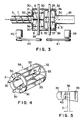
- Fig. 4 represents one preferred embodiment of a rotary drum unit 36 constituting the rotary drum assembly 2A or 2B.
- the rotary drum unit 36 comprises a ring shaped end plate 31 constituting the hot blast sucking side, a disc end plate 32, a plurality of, six in the illustrated embodiment, blade members each in the shape of a plate 33, 33, ... extending in the axial direction of the unit 36 between both the end plates 31 and 32 so that the width of each of the blades 33 gradually decreases towards the ring shaped end plate 31, a plurality of (six in the illustrated embodiment) scattering vanes 30, 30, ... disposed on the outer peripheral surface of the ring shaped end plate 31 so as to extend axially outwardly each in shape of a spoon, and a boss 35 provided with an axial bore 34 and disposed inside the disc end plate 32.
- the rotary drum assembly 2A on the hot gas blasting side includes, as shown in Fig. 3, two rotary drum units 36 mounted on a shaft 37 through the axial bores of the bosses 35 and 35 so that the scattering vanes 30 and 30 of the respective rotary drum units 36 and 36 are opposed to each other and the bosses 35 and 35 are secured to the shaft 37 by means of bolts, for example, to define a space A between the opposing ring shaped end plates 31 and 31 of the respective rotary drum units 36 and 36.
- the rotary drum assembly 2B on the material feeding side includes, also as shown in Fig. 3, two rotary vane units 36 and 36 so that the disc end plates 32 and 32 of the respective units 36 and 36 are tightly engaged and axially aligned so as to be supported by a shaft 38 inserted through the axial bores of the bosses 35 and 35.
- the bosses 35 and 35 are secured to the shaft 38 by means of bolts, for example, to define spaces B and B between the scattering vanes 30 and 30 of the ring shaped end plates 31 and 31 and the inner wall surface of the fluidization drying column 1.
- each of the rotary drum units is rotated at a rotating speed of about 1500 r.p.m., and more specifically, about 1000 r.p.m. in case of utilizing a rotary drum unit having a diameter of about 600 mm, or about 3000 r.p.m. in the case of utilizing a rotary drum unit having a diameter of about 300 mm.
- the scattering vanes 30 are formed integrally with the ring shaped end plate 31, the scattering or splashing vanes 30 may be formed independently of the end plate 31 as shown in Fig. 5, in which the scattering vanes 30 can be secured to the end plate 31 by means of bolts 43 or the like.
- various kinds of scattering vanes each having an axial length different from each other can be attached in accordance with the sizes or properties of the materials to be treated.
- the scattering vanes may be easily secured to the ring shaped end plate 31 by bolt means 43 at intermediate portions between the attaching portions of the adjacent blades 33 and 33.
- axially slidable scattering vanes 30 may be secured to the end plate 31 so that the axial length thereof can be adjusted.
- a sound detector 44 may be located on the side wall of the fluidization drying column 1 at a portion near the rotary drum assemblies 2A and 2B to detect the sound generated by colliding the foreign materials against the blades 33, and transmit a detection signal as an alarm signal at a time when the colliding sound exceeds a predetermined level.
- the bottom portion of the fluidization drying column 1 is composed of bottom plates 45 and 45 to be downwardly opened and closed.
- the bottom plates 45 and 45 are positioned directly below the rotary drum assemblies 2A and 2B, respectively, and the base ends of the bottom plates 45 and 45 are pivotally secured to the lowermost portions of the fluidization drying column 1 so as to occupy the opened positions as shown by dotted lines in Fig. 2.
- the bottom plates 45 and 45 constitute a flat bottom portion of the drying column 1 when closed.
- each of the driving mechanisms 47 and 47 comprises a pneumatic cylinder assembly 48 having a base end pivotally secured to a stationary side.
- the pneumatic cylinder assemblies 48 and 48 are actuated so that rod members 49 and 49 of the respective pneumatic cylinder assemblies 48 and 48 are contracted to open the bottom plates 45 and 45 and expanded to close the same.
- the actuation of the pneumatic cylinder assemblies 48 and 48 is performed in response to the signal transmitted from the sound detector 44 at a time when the detector detects the colliding sound at the predetermined level.
- the existence of the foreign materials may be detected by detecting the overload applied to the driving mechanism for the rotary drum assemblies 2A and 2B. Hydraulic cylinder assemblies or a combined mechanism of motors and crank members may be utilized instead of the pneumatic cylinder assemblies.
- the foreign material is recovered by a sealed recovery box 50 disposed below the bottom plates 45 and 45, which are accommodated in the box 50.
- the shredding and fluidization drying apparatus generally operates as a whole in a manner that undried material is continuously fed to the paddle mixer 4 from the conveyer 3 and the material having a high water content is mixed therein with a dried material powder to reduce the apparent water content.
- the plate-like or massive material is shredded into a fluidizable state in the pre-treatment.
- the material is then fed to the conveyer 5.
- the material is fed into the central portions of the rotary drum assemblies 2A and 2B disposed in the fluidization drying column 1 from the feeding end of the conveyer 5 by way of the material feeding port 6 formed in the wall of the drying column 1 at a portion above the location of the rotary drum assembly.
- the greatest portion of the materials fed into the fluidization column 1 is upwardly fluidized by the ascending current blasted therein during the time when the materials collide with each other and are shredded and the water content thereof is vaporized.
- the foreign materials each having a heavy weight included in the fed materials fall by their own weight and are sucked on the suction side, i.e. on the side of the ring shaped end plate 31, by the blades 33 and 33 of the rotary drum assemblies 2A and 2B.
- the heavy materials collide with the blades 33 and the inner surface of the bottom portion of the drying column 1 to thereby be finally shredded or crushed into dried powders which are then moved upwardly.
- the material moved upwardly in the fluidization drying column 1 is moved into the cyclone separator 9 together with the gas component in which the gas component and the dried powder materials are separated.
- the separated dried materials are fed through the rotary valve 11 to the damper 17 by which the dried materials are further separated.
- One portion of the separated materials is again fed through the branch pipe 16 to the paddle mixer 4 in which the dried materials are mixed with the new material including a high water content.
- the other part of the dried material powder is conveyed to the incinerator 21 to be burnt through the branch pipe 13, the rotary valve 14, and the conveying duct 16 by means of the blower 15.
- the gas component separated in the cyclone separator 9 is conveyed into the dust collector 20 through a duct by means of the discharge blower 19 and is then discharged into the atmosphere after dust removal treatment.
- the material introduced into the fluidization drying column 1 repeatedly collides with the blades 33 and 33 of the rotary drum assemblies 2A and 2B and is finally shredded or crushed into fine powders.
- the locations of the spaces A and B in the rotary drum assemblies 2A and 2B may facilitate the accumulation of the material at the lower portions of the spaces, but the material in the spaces are scooped by the scattering or splashing vanes each in the form of a spoon and agitated thereby, whereby the material shredding or crushing effect can be further improved and promoted. Accordingly, substantially all the material can be upwardly moved by the ascending current in the fluidization drying column 1 and effectively dried.
- colliding noises are generated by the collision between the blades 33 and 33 of the rotary drum assemblies 2A and 2B and the inner wall of the fluidization drying column 1.
- the colliding noises are detected by the sound detector 44, which then transmits noise detecting signals into the driving mechanism 47 and 47 for opening and closing the bottom plates 45 and 45 of the fluidization drying column 1.
- the pneumatic cylinder assemblies 48 and 48 of the driving mechanisms 47 and 47 are contracted to open the bottom plates 45 and 45 to recover the foreign material into the recovery box 50 disposed below the fluidization drying column 1.
- the foreign material can be gathered in a space in the lower portion between the rotary drum assemblies 2A and 2B, whereby the foreign material can be surely recovered by opening the bottom plates 45 and 45.
- the inner space of the fluidization drying column is maintained under a negative pressure, for example, of about 300 mmAg and the inner pressure is lowered when the bottom plates 45 and 45 are opened, but the foreign material recovery box 50 is of a sealed structure, so that an influence due to the opening of the bottom plates is not substantially caused.
- the foreign material recovery box 50 may be provided with the bottom structure capable of being opened and closed as a double damper structure.
- a conveyer is arranged below the recovery box 50 to automatically convey the foreign material out of the apparatus.
Landscapes
- Engineering & Computer Science (AREA)
- Chemical & Material Sciences (AREA)
- Mechanical Engineering (AREA)
- General Engineering & Computer Science (AREA)
- Chemical Kinetics & Catalysis (AREA)
- Organic Chemistry (AREA)
- Combustion & Propulsion (AREA)
- Drying Of Solid Materials (AREA)
- Crushing And Pulverization Processes (AREA)
- Processing Of Solid Wastes (AREA)
- Control And Other Processes For Unpacking Of Materials (AREA)
- Polysaccharides And Polysaccharide Derivatives (AREA)
- Paper (AREA)
- Disintegrating Or Milling (AREA)
- Vaporization, Distillation, Condensation, Sublimation, And Cold Traps (AREA)
Claims (13)
- Dispositif de déchiquetage et de séchage à fluidisation comprenant une colonne de séchage à fluidisation (1) du type dans lequel une matière telle que le papier de rebut ou des déchets industriels est déchiquetée et séchée par fluidisation pour obtenir une fine matière en poudre, comportant deux assemblages à tambours rotatifs (2A, 2B) disposés à la partie inférieure de la colonne de séchage à fluidisation, chacun de ces assemblages étant équipé d'une pluralité de pales de dispersion (30), une paire d'arbres parallèles (37,38), supportés de manière rotative par la colonne de séchage à fluidisation, lesdits arbres supportant lesdits assemblages à tambours rotatifs de manière à ce qu'ils puissent respectivement tourner, un mécanisme d'entraînement (39,40) disposé à l'extérieur de la colonne de séchage à fluidisation pour entraîner lesdits arbres; ladite colonne de séchage à fluidisation étant munie d'un moyen d'alimentation à vent chaud (25) pour produire un vent chaud dans ladite colonne de séchage à fluidisation, et d'un moyen d'alimentation en matière (5) pour alimenter en matière à traiter ladite colonne de séchage à fluidisation, caractérisé en ce que le premier assemblage à tambour rotatif (2A) est positionné du côté d'alimentation à vent chaud (24) de la colonne de séchage à fluidisation (1) et il est pourvu d'un espace (A) dans la partie centrale de celui-ci (2A), espace à travers lequel le vent chaud est soufflé, et la pluralité de premières pales (30) s'étend, et le second assemblage à tambour rotatif (2B) est positionné du côté alimentation en matière (7) de la colonne de séchage à fluidisation (1) et il est pourvu des espaces (B,B) entre les deux extrémités de celui-ci (2B) et une face latérale de la colonne de séchage à fluidisation (1), la pluralité des deuxièmes pales (30) s'étendant à travers lesdits espaces (B,B).
- Un dispositif selon la revendication 1, dans lequel chacun desdits assemblages à tambour rotatif (2A,2B) comprend deux unités à tambour rotatif, chacune de ces unités étant équipé d'une plaque d'extrémité en forme d'anneau (31) et d'une plaque d'extrémité en forme de disque (32), un pluralité d'éléments de pales (33) s'étendant entre lesdits plaques d'extrémité (31,32) suivant la direction de son axe et servant à diriger le vent chaud et déchiqueter la matière introduite dans la colonne de séchage à fluidisation (1), la pluralité de pales (30) étant fixée sur une des faces extérieures de la plaque d'extrémité en forme d'anneau (31) de façon à s'étendre dans la direction de l'axe de l'asssemblage à tambour rotatif (36).
- Dispositif selon la revendication 2, dans lequel les pales (30) sont fixées de manière démontable sur ladite plaque d'extrémité (31) au moyen de boulons (43).
- Dispositif selon la revendication 2, dans lequel chacune desdites pales (30) a la forme d'une cuillère.
- Dispositif selon la revendication 1, dans lequel le moyen d'alimentation à vent chaud est constitué par un orifice (25) réalisé dans la face latérale de la colonne de séchage à fluidisation (1) sur une partie située au-dessus de l'emplacement de l'un desdits assemblages à tambour rotatif (2A).
- Dispositif selon la revendication 1, dans lequel le moyen d'alimentation en matière est constitue, par un orifice (6) réalisé dans la face latérale de la colonne de séchage à fluidisation (1) sur une partie située au-dessus de l'emplacement dudit second assemblage à tambour rotatif (2B).
- Dispositif selon la revendication 1, dans lequel lesdits assemblages à tambour rotatif (2A,2B) sont positionnés, avec un espace entre eux, au-dessus de la paroi inférieure de la colonne de séchage à fluidisation (1).
- Dispositif selon la revendication 7, dans lequel ladite paroi inférieure de la colonne de séchage à fluidisation (1) comprend deux plaques de fond (45) s'ouvrant vers le bas par un mécanisme de commande (47) placé à l'extérieur de ladite colonne de séchage à fluidisation (1).
- Dispositif selon la revendication 8, dans lequel les plaques de fond de la colonne de séchage à fluidisation (1) sont munies de surfaces supérieures qui sont alignées de sorte qu'elles se trouvent de niveau l'une avec l'autre lorsqu'elles sont fermées
- Dispositif selon la revendication 8, dans lequel le mécanisme de commande (47) est un assemblage à cylindres pneumatiques( 48) équipé d'un élément de tige (49) rétrécissable relié à chacune des plaques de fond (45).
- Dispositif selon la revendication 8, comprenant en outre un détecteur de son (44) monté sur la partie inférieure de la face latérale de ladite colonne de séchage à fluidisation (1) pour déceler les bruits provenant de la colonne de séchage à fluidisation (1).
- Dispositif selon la revendication 11, dans lequel le détecteur de son (44) est relié de manière opérationnelle au mécanisme de commande (47) pour ouvrir lesdites plaques de fond (45) lorsqu'on décèle un bruit d'un niveau prédéterminé.
- Dispositif selon la revendication 8, comprenant en outre une boîte de récupération (50) fixée hermétiquement dans la partie inférieure de ladite colonne de fluidisation (1) de sorte que lesdites plaques de fond (45) soient logées à l'intérieur de cette dernière lorsqu'elles sont ouvertes vers le bas.
Priority Applications (1)
| Application Number | Priority Date | Filing Date | Title |
|---|---|---|---|
| AT89118541T ATE100569T1 (de) | 1989-07-19 | 1989-10-06 | Vorrichtung zum zerreissen und zur fluidisierungstrocknung. |
Applications Claiming Priority (2)
| Application Number | Priority Date | Filing Date | Title |
|---|---|---|---|
| JP186644/89 | 1989-07-19 | ||
| JP1186644A JPH0351609A (ja) | 1989-07-19 | 1989-07-19 | 破砕流動乾燥装置 |
Publications (2)
| Publication Number | Publication Date |
|---|---|
| EP0410043A1 EP0410043A1 (fr) | 1991-01-30 |
| EP0410043B1 true EP0410043B1 (fr) | 1994-01-19 |
Family
ID=16192198
Family Applications (1)
| Application Number | Title | Priority Date | Filing Date |
|---|---|---|---|
| EP89118541A Expired - Lifetime EP0410043B1 (fr) | 1989-07-19 | 1989-10-06 | Dispositif de déchiquetage et de séchage à fluidisation |
Country Status (8)
| Country | Link |
|---|---|
| US (1) | US5107604A (fr) |
| EP (1) | EP0410043B1 (fr) |
| JP (1) | JPH0351609A (fr) |
| KR (1) | KR0133172B1 (fr) |
| AT (1) | ATE100569T1 (fr) |
| AU (1) | AU639244B2 (fr) |
| DE (1) | DE68912585T2 (fr) |
| NZ (1) | NZ234544A (fr) |
Cited By (1)
| Publication number | Priority date | Publication date | Assignee | Title |
|---|---|---|---|---|
| US20200348078A1 (en) * | 2018-01-16 | 2020-11-05 | Waister As | Modular System and Process of Drying Solids and Liquid-Solid Mixtures |
Families Citing this family (22)
| Publication number | Priority date | Publication date | Assignee | Title |
|---|---|---|---|---|
| AU656334B2 (en) * | 1990-10-30 | 1995-02-02 | Fukutaro Kataoka | Fluidized crusher/drier for use in a fluidized crusher/drier system |
| JP2759849B2 (ja) * | 1991-03-22 | 1998-05-28 | 片岡エンジニアリング株式会社 | 破砕流動乾燥装置に配する破砕流動乾燥機 |
| JP3160651B2 (ja) * | 1991-10-14 | 2001-04-25 | 月島機械株式会社 | 含水汚泥の乾燥方法及び装置 |
| KR200176580Y1 (ko) * | 1998-04-23 | 2000-04-15 | 정진효 | 여과건조기의 배출구의 개폐장치 |
| JP3710333B2 (ja) | 1999-07-29 | 2005-10-26 | ホソカワミクロン株式会社 | 気流乾燥装置 |
| KR200184520Y1 (ko) * | 1999-11-03 | 2000-06-01 | 신성산건주식회사 | 충격파쇄식 건조시스템 |
| MX2010002794A (es) * | 2007-09-13 | 2010-07-02 | Enviro Energy Ltd | Aparato de molienda y secado y planta de procesamiento. |
| CN102373810B (zh) * | 2011-11-22 | 2013-03-20 | 河北建筑工程学院 | 一种预应力玄武岩纤维布加固木柱的方法 |
| JP6083864B2 (ja) * | 2013-03-27 | 2017-02-22 | 株式会社御池鐵工所 | 有機廃棄物の乾燥システム |
| JP6104666B2 (ja) * | 2013-03-27 | 2017-03-29 | 株式会社御池鐵工所 | 有機廃棄物を用いた熱源システム及び発電システム |
| JP6347542B2 (ja) * | 2014-05-26 | 2018-06-27 | 忠行 猪野 | きのこ廃培地乾燥装置、きのこ廃培地の処理方法、再利用物の作成方法及び乾燥廃培地の作成方法 |
| JP6360724B2 (ja) * | 2014-06-05 | 2018-07-18 | 豊田興産株式会社 | 有機性廃棄物の乾燥装置 |
| JP6485124B2 (ja) * | 2015-03-06 | 2019-03-20 | セイコーエプソン株式会社 | シート製造装置 |
| CN105674298B (zh) * | 2016-03-23 | 2017-10-31 | 商洛市海蓝科技有限公司 | 一种钻井废弃泥浆干化煅烧处理系统 |
| JP6564913B2 (ja) * | 2018-06-15 | 2019-08-21 | 豊田興産株式会社 | 有機性廃棄物の処理方法 |
| RU2701958C1 (ru) * | 2019-02-19 | 2019-10-02 | федеральное государственное бюджетное образовательное учреждение высшего образования "Белгородский государственный технологический университет им. В.Г. Шухова" | Дезинтегратор |
| CN111495520A (zh) * | 2019-07-19 | 2020-08-07 | 河北燕岛环保科技股份有限公司 | 一种垃圾焚烧烟气处理装置 |
| CN111397332B (zh) * | 2020-03-31 | 2021-10-08 | 济南清照生物科技有限公司 | 一种白酒酒糟烘干设备 |
| CN112121926B (zh) * | 2020-09-07 | 2021-12-07 | 聊城锐利机械设备有限公司 | 一种化工生产用原料破碎球磨机 |
| CN112344337A (zh) * | 2020-10-14 | 2021-02-09 | 汪慧 | 一种生活垃圾源头无害化环保处理设备 |
| EP3991567A1 (fr) * | 2020-10-28 | 2022-05-04 | Bühler Insect Technology Solutions AG | Procédé de fabrication d'une farine protéinée à partir d'insectes, en particulier à partir de larves d'insectes et de chrysalides d'insectes, ou à partir de vers et dispositif de séchage destiné à l'utilisation lors d'un tel procédé |
| CN112934408B (zh) * | 2021-01-30 | 2022-10-04 | 淄博泰鼎机械科技有限公司 | 一种造纸用废纸回收破碎设备 |
Family Cites Families (5)
| Publication number | Priority date | Publication date | Assignee | Title |
|---|---|---|---|---|
| GB215812A (en) * | 1923-01-18 | 1924-05-19 | Thomas Rigby | Improvements in or relating to drying processes |
| JPS609228B2 (ja) * | 1978-04-28 | 1985-03-08 | 愛知化工機株式会社 | 流動乾燥機における偏気流発生装置 |
| DE3247303A1 (de) * | 1982-12-21 | 1984-07-05 | Ukrainskij naučno-issledovatel'skij institut myasnoi i molochnoi promyshlennosti, Kiev | Einrichtung zur zerkleinerung und gleichzeitigen trocknung von waermeempfindlichem gut |
| JPS609228A (ja) * | 1983-06-28 | 1985-01-18 | Fujitsu Ten Ltd | ラジオ受信機 |
| JPS61291822A (ja) * | 1985-06-20 | 1986-12-22 | Ryowa Kakoki Kk | 流動分級乾燥装置 |
-
1989
- 1989-07-19 JP JP1186644A patent/JPH0351609A/ja active Pending
- 1989-09-29 US US07/414,957 patent/US5107604A/en not_active Expired - Fee Related
- 1989-10-06 EP EP89118541A patent/EP0410043B1/fr not_active Expired - Lifetime
- 1989-10-06 DE DE68912585T patent/DE68912585T2/de not_active Expired - Fee Related
- 1989-10-06 AT AT89118541T patent/ATE100569T1/de not_active IP Right Cessation
- 1989-10-26 KR KR1019890015417A patent/KR0133172B1/ko not_active Expired - Fee Related
-
1990
- 1990-07-17 NZ NZ234544A patent/NZ234544A/xx unknown
- 1990-07-17 AU AU59079/90A patent/AU639244B2/en not_active Ceased
Cited By (3)
| Publication number | Priority date | Publication date | Assignee | Title |
|---|---|---|---|---|
| US20200348078A1 (en) * | 2018-01-16 | 2020-11-05 | Waister As | Modular System and Process of Drying Solids and Liquid-Solid Mixtures |
| EP3737900A4 (fr) * | 2018-01-16 | 2022-03-16 | Waister AS | Système modulaire et procédé de séchage de solides et de mélanges liquides-solides |
| US12460864B2 (en) * | 2018-01-16 | 2025-11-04 | Waister As | Modular system and process of drying solids and liquid-solid mixtures |
Also Published As
| Publication number | Publication date |
|---|---|
| US5107604A (en) | 1992-04-28 |
| DE68912585D1 (de) | 1994-03-03 |
| KR0133172B1 (ko) | 1998-04-17 |
| AU639244B2 (en) | 1993-07-22 |
| ATE100569T1 (de) | 1994-02-15 |
| EP0410043A1 (fr) | 1991-01-30 |
| AU5907990A (en) | 1991-01-24 |
| JPH0351609A (ja) | 1991-03-06 |
| KR910003343A (ko) | 1991-02-27 |
| NZ234544A (en) | 1992-11-25 |
| DE68912585T2 (de) | 1994-06-16 |
Similar Documents
| Publication | Publication Date | Title |
|---|---|---|
| US5107604A (en) | Shredding and fluidization drying apparatus | |
| US4043901A (en) | Wood chip screens | |
| US3826208A (en) | Apparatus and system for disposing of combustible and waste material | |
| CA1069084A (fr) | Separateur de dechets a tambour rotatif, incline | |
| JP3512291B2 (ja) | ごみからの固形燃料製造方法及び装置 | |
| JP2000167487A (ja) | 乾燥機構付選別機 | |
| JP2859580B2 (ja) | ガラス製品のリサイクルプラント | |
| JP2001133151A (ja) | 熱風乾燥機 | |
| JP2001327885A (ja) | 破袋選別機 | |
| JP2000263028A (ja) | 一般ゴミの破砕乾燥選別装置 | |
| CA1243901A (fr) | Appareil pour la separation d'un milieu de fluidisation et d'un residu incombustible | |
| JPS5857650B2 (ja) | 給じん装置 | |
| JP2733902B2 (ja) | 焼却炉 | |
| AU656334B2 (en) | Fluidized crusher/drier for use in a fluidized crusher/drier system | |
| KR20170142049A (ko) | 입자형 폐기물을 처리하기 위한 건조장치 | |
| JPS592841Y2 (ja) | 列車ごみの選別装置 | |
| JPH0351623Y2 (fr) | ||
| JP3540189B2 (ja) | 回転式乾燥機 | |
| JP3831552B2 (ja) | 廃石膏ボ−ド破砕分別処理装置 | |
| JPH08166115A (ja) | 気流選別乾燥装置 | |
| JP2504355B2 (ja) | 廃棄物流動床焼却炉の前処理用破砕選別装置 | |
| JPS6146725B2 (fr) | ||
| JP2003262320A (ja) | 不燃物排出装置 | |
| JP2000005615A (ja) | 石炭粉砕機の運転方法 | |
| JP2759849B2 (ja) | 破砕流動乾燥装置に配する破砕流動乾燥機 |
Legal Events
| Date | Code | Title | Description |
|---|---|---|---|
| PUAI | Public reference made under article 153(3) epc to a published international application that has entered the european phase |
Free format text: ORIGINAL CODE: 0009012 |
|
| AK | Designated contracting states |
Kind code of ref document: A1 Designated state(s): AT DE SE |
|
| 17P | Request for examination filed |
Effective date: 19910326 |
|
| 17Q | First examination report despatched |
Effective date: 19910711 |
|
| RAP1 | Party data changed (applicant data changed or rights of an application transferred) |
Owner name: KABUSHIKI KAISHA SHINRYO SEISAKUSHO |
|
| GRAA | (expected) grant |
Free format text: ORIGINAL CODE: 0009210 |
|
| AK | Designated contracting states |
Kind code of ref document: B1 Designated state(s): AT DE SE |
|
| REF | Corresponds to: |
Ref document number: 100569 Country of ref document: AT Date of ref document: 19940215 Kind code of ref document: T |
|
| REF | Corresponds to: |
Ref document number: 68912585 Country of ref document: DE Date of ref document: 19940303 |
|
| PGFP | Annual fee paid to national office [announced via postgrant information from national office to epo] |
Ref country code: AT Payment date: 19940926 Year of fee payment: 6 |
|
| PGFP | Annual fee paid to national office [announced via postgrant information from national office to epo] |
Ref country code: SE Payment date: 19941018 Year of fee payment: 6 |
|
| PLBE | No opposition filed within time limit |
Free format text: ORIGINAL CODE: 0009261 |
|
| STAA | Information on the status of an ep patent application or granted ep patent |
Free format text: STATUS: NO OPPOSITION FILED WITHIN TIME LIMIT |
|
| PGFP | Annual fee paid to national office [announced via postgrant information from national office to epo] |
Ref country code: DE Payment date: 19941221 Year of fee payment: 6 |
|
| 26N | No opposition filed | ||
| EAL | Se: european patent in force in sweden |
Ref document number: 89118541.5 |
|
| PG25 | Lapsed in a contracting state [announced via postgrant information from national office to epo] |
Ref country code: AT Effective date: 19951006 |
|
| PG25 | Lapsed in a contracting state [announced via postgrant information from national office to epo] |
Ref country code: SE Effective date: 19951007 |
|
| EUG | Se: european patent has lapsed |
Ref document number: 89118541.5 |
|
| PG25 | Lapsed in a contracting state [announced via postgrant information from national office to epo] |
Ref country code: DE Effective date: 19960801 |