EP0410159A1 - Collecteur de courant pour pile à combustible fonctionnant à haute température - Google Patents
Collecteur de courant pour pile à combustible fonctionnant à haute température Download PDFInfo
- Publication number
- EP0410159A1 EP0410159A1 EP90112438A EP90112438A EP0410159A1 EP 0410159 A1 EP0410159 A1 EP 0410159A1 EP 90112438 A EP90112438 A EP 90112438A EP 90112438 A EP90112438 A EP 90112438A EP 0410159 A1 EP0410159 A1 EP 0410159A1
- Authority
- EP
- European Patent Office
- Prior art keywords
- current collector
- collector according
- contact
- fuel
- plate
- Prior art date
- Legal status (The legal status is an assumption and is not a legal conclusion. Google has not performed a legal analysis and makes no representation as to the accuracy of the status listed.)
- Withdrawn
Links
- 239000000446 fuel Substances 0.000 title claims abstract description 72
- QVGXLLKOCUKJST-UHFFFAOYSA-N atomic oxygen Chemical compound [O] QVGXLLKOCUKJST-UHFFFAOYSA-N 0.000 claims abstract description 29
- 239000001301 oxygen Substances 0.000 claims abstract description 29
- 229910052760 oxygen Inorganic materials 0.000 claims abstract description 29
- 239000000919 ceramic Substances 0.000 claims abstract description 22
- MCMNRKCIXSYSNV-UHFFFAOYSA-N Zirconium dioxide Chemical compound O=[Zr]=O MCMNRKCIXSYSNV-UHFFFAOYSA-N 0.000 claims abstract description 12
- 239000007784 solid electrolyte Substances 0.000 claims abstract description 12
- 230000007774 longterm Effects 0.000 claims abstract description 6
- 230000001681 protective effect Effects 0.000 claims abstract description 4
- 238000005192 partition Methods 0.000 claims description 30
- 239000000463 material Substances 0.000 claims description 15
- 238000003466 welding Methods 0.000 claims description 11
- 210000001520 comb Anatomy 0.000 claims description 10
- 239000011195 cermet Substances 0.000 claims description 5
- 239000004744 fabric Substances 0.000 claims description 5
- 238000005476 soldering Methods 0.000 claims description 5
- 239000002131 composite material Substances 0.000 claims description 4
- 239000000203 mixture Substances 0.000 claims description 4
- 239000007787 solid Substances 0.000 claims description 4
- 239000007789 gas Substances 0.000 claims description 3
- 230000001590 oxidative effect Effects 0.000 claims description 3
- RVTZCBVAJQQJTK-UHFFFAOYSA-N oxygen(2-);zirconium(4+) Chemical compound [O-2].[O-2].[Zr+4] RVTZCBVAJQQJTK-UHFFFAOYSA-N 0.000 claims description 3
- 238000005245 sintering Methods 0.000 claims description 3
- 229910001928 zirconium oxide Inorganic materials 0.000 claims description 3
- PXHVJJICTQNCMI-UHFFFAOYSA-N nickel Substances [Ni] PXHVJJICTQNCMI-UHFFFAOYSA-N 0.000 description 13
- 238000004519 manufacturing process Methods 0.000 description 9
- XEEYBQQBJWHFJM-UHFFFAOYSA-N Iron Chemical compound [Fe] XEEYBQQBJWHFJM-UHFFFAOYSA-N 0.000 description 8
- 239000002184 metal Substances 0.000 description 7
- 229910052751 metal Inorganic materials 0.000 description 7
- 238000010276 construction Methods 0.000 description 6
- 229910045601 alloy Inorganic materials 0.000 description 5
- 239000000956 alloy Substances 0.000 description 5
- 229910000599 Cr alloy Inorganic materials 0.000 description 3
- 229910010293 ceramic material Inorganic materials 0.000 description 3
- 230000018109 developmental process Effects 0.000 description 3
- 238000006073 displacement reaction Methods 0.000 description 3
- 229910052759 nickel Inorganic materials 0.000 description 3
- HBMJWWWQQXIZIP-UHFFFAOYSA-N silicon carbide Chemical compound [Si+]#[C-] HBMJWWWQQXIZIP-UHFFFAOYSA-N 0.000 description 3
- 229910010271 silicon carbide Inorganic materials 0.000 description 3
- 229910000838 Al alloy Inorganic materials 0.000 description 2
- 238000006243 chemical reaction Methods 0.000 description 2
- 239000000835 fiber Substances 0.000 description 2
- 229910052742 iron Inorganic materials 0.000 description 2
- 238000000034 method Methods 0.000 description 2
- 230000003647 oxidation Effects 0.000 description 2
- 238000007254 oxidation reaction Methods 0.000 description 2
- 238000003825 pressing Methods 0.000 description 2
- 238000005096 rolling process Methods 0.000 description 2
- 241000195955 Equisetum hyemale Species 0.000 description 1
- 229910000990 Ni alloy Inorganic materials 0.000 description 1
- 229910000831 Steel Inorganic materials 0.000 description 1
- 230000006978 adaptation Effects 0.000 description 1
- 239000000853 adhesive Substances 0.000 description 1
- 230000001070 adhesive effect Effects 0.000 description 1
- 239000012300 argon atmosphere Substances 0.000 description 1
- 230000004888 barrier function Effects 0.000 description 1
- 238000005219 brazing Methods 0.000 description 1
- 230000011712 cell development Effects 0.000 description 1
- 229910021525 ceramic electrolyte Inorganic materials 0.000 description 1
- VNNRSPGTAMTISX-UHFFFAOYSA-N chromium nickel Chemical compound [Cr].[Ni] VNNRSPGTAMTISX-UHFFFAOYSA-N 0.000 description 1
- 239000011248 coating agent Substances 0.000 description 1
- 238000000576 coating method Methods 0.000 description 1
- 230000001427 coherent effect Effects 0.000 description 1
- 239000004020 conductor Substances 0.000 description 1
- 238000001816 cooling Methods 0.000 description 1
- 238000009792 diffusion process Methods 0.000 description 1
- 238000009826 distribution Methods 0.000 description 1
- 230000005489 elastic deformation Effects 0.000 description 1
- 239000003792 electrolyte Substances 0.000 description 1
- 238000005516 engineering process Methods 0.000 description 1
- 210000004013 groin Anatomy 0.000 description 1
- 238000007373 indentation Methods 0.000 description 1
- 239000010416 ion conductor Substances 0.000 description 1
- 230000002427 irreversible effect Effects 0.000 description 1
- 229910001120 nichrome Inorganic materials 0.000 description 1
- 239000002245 particle Substances 0.000 description 1
- 238000005554 pickling Methods 0.000 description 1
- 239000010970 precious metal Substances 0.000 description 1
- 238000004080 punching Methods 0.000 description 1
- 230000002829 reductive effect Effects 0.000 description 1
- 230000000284 resting effect Effects 0.000 description 1
- 230000000717 retained effect Effects 0.000 description 1
- 229910000679 solder Inorganic materials 0.000 description 1
- 239000007921 spray Substances 0.000 description 1
- 239000007858 starting material Substances 0.000 description 1
- 239000010959 steel Substances 0.000 description 1
- 239000000126 substance Substances 0.000 description 1
- 238000004804 winding Methods 0.000 description 1
Images


Classifications
-
- H—ELECTRICITY
- H01—ELECTRIC ELEMENTS
- H01M—PROCESSES OR MEANS, e.g. BATTERIES, FOR THE DIRECT CONVERSION OF CHEMICAL ENERGY INTO ELECTRICAL ENERGY
- H01M8/00—Fuel cells; Manufacture thereof
- H01M8/02—Details
- H01M8/0202—Collectors; Separators, e.g. bipolar separators; Interconnectors
-
- H—ELECTRICITY
- H01—ELECTRIC ELEMENTS
- H01M—PROCESSES OR MEANS, e.g. BATTERIES, FOR THE DIRECT CONVERSION OF CHEMICAL ENERGY INTO ELECTRICAL ENERGY
- H01M8/00—Fuel cells; Manufacture thereof
- H01M8/10—Fuel cells with solid electrolytes
- H01M8/12—Fuel cells with solid electrolytes operating at high temperature, e.g. with stabilised ZrO2 electrolyte
- H01M2008/1293—Fuel cells with solid oxide electrolytes
-
- H—ELECTRICITY
- H01—ELECTRIC ELEMENTS
- H01M—PROCESSES OR MEANS, e.g. BATTERIES, FOR THE DIRECT CONVERSION OF CHEMICAL ENERGY INTO ELECTRICAL ENERGY
- H01M2300/00—Electrolytes
- H01M2300/0017—Non-aqueous electrolytes
- H01M2300/0065—Solid electrolytes
- H01M2300/0068—Solid electrolytes inorganic
- H01M2300/0071—Oxides
- H01M2300/0074—Ion conductive at high temperature
-
- Y—GENERAL TAGGING OF NEW TECHNOLOGICAL DEVELOPMENTS; GENERAL TAGGING OF CROSS-SECTIONAL TECHNOLOGIES SPANNING OVER SEVERAL SECTIONS OF THE IPC; TECHNICAL SUBJECTS COVERED BY FORMER USPC CROSS-REFERENCE ART COLLECTIONS [XRACs] AND DIGESTS
- Y02—TECHNOLOGIES OR APPLICATIONS FOR MITIGATION OR ADAPTATION AGAINST CLIMATE CHANGE
- Y02E—REDUCTION OF GREENHOUSE GAS [GHG] EMISSIONS, RELATED TO ENERGY GENERATION, TRANSMISSION OR DISTRIBUTION
- Y02E60/00—Enabling technologies; Technologies with a potential or indirect contribution to GHG emissions mitigation
- Y02E60/30—Hydrogen technology
- Y02E60/50—Fuel cells
Definitions
- High-temperature fuel cells for converting chemical energy into electrical energy Thanks to their good efficiency, the electrochemical energy conversion and the devices required for this are gaining importance compared to other types of conversion.
- the invention relates to the further development of electrochemical high-temperature cells using ceramic solid electrolytes as ion conductors, the cells being said to be largely independent of the fuel used and to provide a space-saving arrangement.
- the invention relates to a current collector for carrying current between adjacent flat, flat, stacked high-temperature fuel cells with solid electrolyte based on doped, stabilized zirconium oxide, the oxygen electrode of one fuel cell being electrically connected to the fuel electrode of the next fuel cell and the one between the gap between the electrodes is divided by a gas-tight, electrically conductive separating plate into two, the different gaseous media containing fuel and oxygen carrier.
- High-temperature fuel cells with ceramic solid electrolyte are known from numerous publications.
- the actual elements for such cells can have a wide variety of shapes and dimensions. In order to keep the ohmic voltage losses small, every effort is made to keep the thickness of the electrolyte layer as low as possible.
- the shape and dimensions of the elements also depend on the requirement of the possibility of series electrical connection of a large number of cells in order to achieve the necessary terminal voltage and to keep the currents comparatively low.
- the known basic elements used for the fuel cells are usually characterized by a comparatively complicated geometry, which makes the construction of compact, space-saving systems difficult.
- rational production on a large industrial scale is hardly possible.
- the invention has for its object to provide a current collector for carrying current between flat, flat, stacked high-temperature fuel cells with solid electrolyte, which, arranged on both sides of the space between adjacent fuel cells in two separating the different gaseous media fuel and oxygen carrier, one flawless current transfer with minimal losses guaranteed both at the contact points and in the electrical conductor itself and guaranteed unchanged, long-term stable operation without interruption.
- the production of the current collector should be reproducible and cost-effective and should be easy to replace on the occasion of checking and examining specifically interrupted operations or revisions.
- the current collector mentioned at the outset consists of a large number of long-term stable, fully elastic at an operating temperature of 800 to 1000 ° C, which in turn ensures a large number of electrical contact points, non-oxidizing or at least on the oxygen side or forming a high-temperature protective oxide consists of a metallic and / or ceramic material or of a composite material containing metallic and / or ceramic components and is designed such that it has a deflection of at least 0.1 mm under a load of 10 3 Pa applied perpendicular to the plane of the plate.
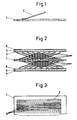
- Fig. 1 is an elevation / longitudinal section through a partition plate with a contact finger as a current collector. 1 is made of a heat-resistant, oxidation-resistant alloy or a dense, electrically conductive ceramic material standing, gas-tight, flat partition plate. A single element 2 of the current collector in the form of a contact finger is firmly connected to it in an electrically conductive manner.
- Fig. 2 shows an elevation / longitudinal section through a partition plate with current collectors on both sides and adjacent parallel, flat fuel cells.
- 1 is the gas-tight electrically conductive partition plate on which the current collector 3 consisting of numerous contact fingers is fastened on the fuel side.
- a corresponding, symmetrically arranged current collector 4 is located on the oxygen side.
- Each of the adjacent fuel cells touched by the current collectors 3 and 4 consists of the ceramic solid electrolyte (doped, stabilized ZrO2) 5, the porous (positive) oxygen electrode 6 made of La / Mn perovskite and the porous (negative) fuel electrode 7 made of Ni / ZrO2- Cermet.
- the current collectors 3 and 4 are constructed from a large number of individual contact fingers arranged crosswise in several parallel planes.
- Fig. 3 shows a plan view of a partition plate with a current collector on the gas side.
- the design corresponds essentially to the upper part of FIG. 2.
- FIG 4 shows a plan view of a partition plate with a current collector in the form of a comb.
- the current collector 8 in the form of a comb represents a coherent body punched from a plurality of individual contact fingers from a sheet or strip.
- the web of this comb-like structure is firmly connected to the separating plate 1 via the connection points 9 (welding or soldering points).
- FIG. 5 shows an elevation / longitudinal section through a separating plate with a current collector in the form of a double comb.
- 10 is a current collector of this type standing in a first row, 11 a current collector standing in a second row and offset from that in the first row.
- the current collectors punched out of sheet metal are fastened to the separating plate 1 analogously to FIG. 4.
- Fig. 6 relates to a floor plan of a partition plate with a current collector in the form of a double comb.
- the arrangement essentially corresponds to that of FIG. 5.
- the various double combs are nested one inside the other in such a way that a crosswise arrangement is formed and the largest possible area is covered.
- FIG. 7 shows an elevation / longitudinal section and a side elevation / cross section through a partition plate and an adjacent fuel cell with a helical current collector in between.
- a current collector 12 in the form of an oblique spiral (helical spring) is clamped between the partition plate 1 and the fuel cell (5; 6; 7).
- the turns of the helix resting on the separating plate 1 are firmly anchored to it via the connection points 13 (welding point, soldering point, sintering point). Due to the inclination of the turns with respect to the longitudinal axis of the helix, a comparatively soft spring (low spring constant) is formed, which is desirable to absorb the unevenness.
- FIG. 8 shows a schematic elevation / longitudinal section and a side elevation / cross section of a helical current collector.
- the illustration corresponds to that of FIG. 7 and shows the deformations and displacements generated under the compressive force p acting perpendicular to the plate plane.
- 12 is the current collector under the load pressure p, 12 * the current collector in the unloaded state.
- the elliptical cross-section which is caused anyway by the inclination of the turns the helix experiences a further increase in its eccentricity under the load.
- FIG. 9 shows a schematic perspective illustration of the production of a helical current collector from a ceramic fiber.
- a vessel 14 is provided for the ceramic melt 15.
- 16 is a rotating, longitudinally displaceable mandrel onto which a thin pouring jet (thread 17 made of ceramic melt I5 is applied.
- the rotating as well as the longitudinal movement of the mandrel 16 is indicated by arrows.
- 18 is the spiral made of ceramic melt 15 produced in this way.
- the wave-shaped current collector 19 * consisting of a wire, ribbon, mesh, mesh or sieve, is shown in the position which occurs perpendicular to the plate plane under the influence of the load (pressure force p). 1 is the partition plate; the fuel cell (5; 6; 7), which actually consists of 3 layers, corresponds to that of the previous figures.
- the initial shape of the originally unloaded current collector is indicated by 19 *.
- FIG. 11 shows a schematic perspective illustration of a wave-shaped current collector.
- the current collector 19, which consists of individual wavy wires, has a stiffening strip 20 as a cross connection on two opposite sides.
- the waves of the individual wires 19 are offset from one another in order to ensure the most uniform possible distribution of the pressure forces acting across the entire plate plane at the contact points and a good current transfer.
- the Current collector 21 is designed in the form of a corrugated wire mesh or provided with knobs and depressions.
- the profiles (bulges, indentations) in one row are offset by half a division from those in the next row in order to ensure that the contact between the entire cross section of the separating plate and the fuel cell is as uniform as possible.
- FIG. 13 relates to a schematic section through a profiled current collector made of metal mesh.
- a current collector 22 in the form of a pleated fabric.
- the deformation and displacement ratios of this arrangement are comparable to those in FIG. 10.
- FIG. 14 shows an elevation / longitudinal section through a separating plate and an adjacent fuel cell with a pointedly corrugated current collector in between.
- the reference numerals 1, 5, 6 and 7 correspond exactly to those of Fig. 10.
- 23 is a current collector in the form of a pointed corrugated wire. This reduces the contact areas compared to the classic sinusoidal design and increases the specific contact pressure accordingly.
- FIG. 15 shows a schematic perspective illustration and a cross section of a current collector corrugated in two planes.
- the wire which is originally in one plane as a sine line (indicated by a dashed wave train), is bent around its center line in two planes at a certain angle (for example 120 °). 24 shows this current collector in the form of a wire corrugated in two planes.
- FIG. 16 shows a schematic elevation / cross section and a side elevation of a current collector corrugated in two planes and consisting of a multiplicity of wire elements
- Cross-section V-shaped foot-standing current collectors 25 in the form of wires corrugated in two planes alternate with corresponding head-standing current collectors 26. Both groups (25 and 26) are held together by stiffening strips 20 as cross connections on opposite sides.
- FIG. 17 shows a schematic plan view of a current collector which is corrugated in two planes.
- the basic structure corresponds to that of Fig. 16.
- the waves are pointed to keep the contact area located in the apex of the sinusoidal arch part small.
- the reference numerals correspond to those in FIG. 16.
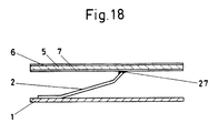
- FIG. 18 shows an elevation / longitudinal section through a separating plate and an adjacent fuel cell with a sintered current collector lying in between.
- the structure largely corresponds to Fig. 1.
- 1 is the partition plate made of a heat-resistant alloy
- 2 is a single element of the current collector.
- a sintered connection 27 to the porous fuel electrode 7 made of Ni / ZrO 2 cermet is provided here.
- 5 is the solid electrolyte made of ZrO2, 6 the porous oxygen electrode. Thermal expansions are absorbed by elastic deformations of the comparatively long lamellar part of the current collector 2.
- a current collector consisting of individual contact fingers 2 and a separating plate 1 was made from a heat-resistant, oxidation-resistant iron-based alloy with the material number 1.4762 according to the German standard DIN with the designation X10CrAl24.
- the 0.8 mm thick partition plate 1 was rectangular and had a length of 70 mm and a width of 35 mm.
- the contact fingers 2 made from the same material by rolling a wire had the following dimensions: Length: approx. 21 mm Height for the oxygen side: approx. 6 mm Height for the fuel side: approx. 3 mm Width: approx. 2 mm Thickness: approx. 0.2 mm
- the foot of the contact finger to be connected to the separating plate 1 had a length (horizontal) of approx. 3 mm, the head located at the other end had a height (vertical) of approx. 1 mm.
- the angle enclosed between the contact finger 2 and the separating plate 1 was approximately 12 ° for the oxygen side (air) and approximately 5 ° for the fuel side (CH4).
- One contact finger 2 each on the oxygen side and on the fuel side was firmly connected to the separating plate 1 in a spot welding machine equipped with a corresponding holding device. In this way, several rows of contact fingers 2, alternatingly directed to one side and to the other, were assembled to form current collectors 3 (fuel side) and 4 (oxygen side).
- a component consisting of several rows of contact fingers similar to 2 (cf. FIG. 1) and a separating plate 1 for current conduction was constructed from stamped sheet metal parts.
- the material used was an Fe / Cr / Al alloy with the number 1.4767 according to DIN with the designation CrAl 20 5.
- the separating plate 1 had the same dimensions as in Example 1.
- a number of current collectors 8 were punched out from a 0.2 mm thick sheet in the form of a comb.
- the individual contact fingers had a width of 1.2 mm.
- the lateral space between two contact fingers was 2 mm.
- the back of the comb consisted of a bar about 3 mm wide.
- the combs were brought into the shape of the individual contact finger corresponding to FIG. 1 by pressing, the geomes trie largely corresponded to that of Example 1.
- the combs were mutually pushed into each other in such a way that the remaining lateral space (play) between adjacent, crossing contact fingers was 0.4 mm.
- the combs were stapled at their groin parts by welding points 9 with the separating plate 1 and additionally firmly connected over the entire area by a high-temperature solder.
- the soldering was carried out under vacuum at a temperature of 1200 ° C.
- the sharp cut edges of the heads of the contact fingers that were created during punching were etched away and rounded off by pickling.
- the finished bodies were straightened in the same manner as described in Example 1.
- the separating plate had a thickness of 0.6 mm, a length of 50 mm and a width of 30 mm.
- the individual contact fingers of a double comb had the following dimensions: Length: approx. 7 mm Height for the oxygen side: approx. 3 mm Height for the fuel side: approx. 2 mm Width: about 0.8 mm Thickness: approx.0.08 mm
- the current-carrying component consisted of a gas-tight, electrically conductive separating plate 1 and a current collector 12 in the form of oblique coils.
- the material NiCr80 20 mentioned in Example 3 was used for both.
- the bare-ground partition plate 1 had a thickness of 0.3 mm.
- a wire of 0.15 mm was wound into a coil (coil spring) of about 7 mm winding diameter and divided into sections that corresponded to the width of the separating plate 1. Then, the ends of each coil were tack-welded to the partition plate 1.
- the helix was deformed in its longitudinal axis by applying a load perpendicular to the plate plane under horizontal thrust in such a way that the turns assumed an oval cross-section and the turns came to be at an angle to the plate plane (see FIGS. 7 and 8).
- the height of the helix perpendicular to the plate plane was still approx. 3 mm for the fuel side and 4 mm for the oxygen side.
- the current collector on the fuel side had approximately the geometric shape of an oblique spiral (see FIG. 12 in FIG. 7). It was produced from a ceramic melt 15 in the form of a pouring jet 17 applied to a rotating, longitudinally displaceable mandrel 16. Silicon carbide was used as the material, which has a comparatively good metallic electrical conductivity at operating temperature. The helix 18 made of solidified ceramic melt was produced directly in the final oblique-angled shape by the mandrel 16 being guided in its movements in the manner of the indicated arrows.
- the partition plate 1 (see FIG. 7) was designed as a ceramic composite construction and consisted of a 1.5 mm thick plate of densely sintered silicon carbide on the fuel side, and a 200 ⁇ m thick layer of a strontium-doped La on the oxygen side of the plasma spray process / Mn perovskite. In between, there was a 60 ⁇ m thick nickel layer, previously galvanically applied to the silicon carbide plate, as a diffusion barrier. Several helices 18 were screwed into each other like a screw, so that a kind of "carpet" with numerous contact points was created.
- Wavy current collectors 19 made of the iron-based alloy X10CrAl24 were produced from a 0.15 mm thick, 1.2 mm wide band (see Example 1). A large number of such strips were connected at one end by means of spot welding via a flat strip-shaped strip (see FIG. 11). In the unloaded state, the current collectors had the shape indicated by the reference number 19 *. Under the influence of the load (pressure force p), they could deform freely and move laterally, which is indicated by the reference number 19 (operating state).
- the waveform does not necessarily have to be a sinusoid. Any waveforms such as triangle, rectangle, trapezoid, asymmetrical, oblique waves etc. can be realized.
- the shapes depend, among other things, on the spring constant (stiffness, deflection) of the current collector to be achieved.
- the wave-shaped current collector 19 consisted of a comb-like body punched out of a 0.1 mm thick sheet (see FIG. 4), the 1 mm wide slats of which were connected were corrugated in a rolling device. The wavelength was approximately 6 mm. The deflection in the installed state was approx. 0.10 mm under a load perpendicular to the plate plane of approx. 5 ⁇ 10 ⁇ 2 N per shaft.
- Wavy current collectors 19 made of the Fe / Cr / Al alloy CrAl20 5 were produced from a wire 0.25 mm thick (see Example 2). A large number of such wires were connected at both ends via a flat band-shaped stiffening strip 20 (cross connection) by spot welding to form a grid-like body. Then this current collector was placed on a smoothed separating plate 1 made of the same material, loaded perpendicular to the plane of the plate and sintered under vacuum at 1200 ° C. for 3 hours at the contact points (locally welded). In contrast to example 6 (FIG. 10), there is no lateral movement here. Thanks to the low section modulus of the comparatively thin wire, the necessary flexibility in the vertical direction is guaranteed.
- a current collector 21 in the form of a wire mesh provided with knobs and depressions was produced for the fuel side from pure nickel.
- the alloy NiCr80 20 (see example 3) was used for the oxygen side.
- the mesh size of the wire mesh was approximately 0.3 mm, the wire thickness 0.1 mm.
- the wire meshes were deformed in a press device to form 2 or 3 mm high, corrugated or studded profiled bodies.
- the deflection under a load of 8 ⁇ 10-2 N per elevation was approx. 0.08 mm.
- a current collector 22 was made in the form of a pleated fabric.
- the material X10CrA124 used for the metal mesh corresponded to that of Example 1.
- the wire of the metal mesh had a diameter of 0.1 mm.
- the mesh size was 0.6 mm.
- the fabric was pleated in folds with a pitch of approx. 3 mm and a total height (double amplitude) of approx. 1.6 mm.
- the average distance between the point contacts was approx. 3 mm.
- the effective contact area of the electrical contact points was reduced in order to increase the specific contact pressure and to achieve the lowest possible contact resistance.
- a current collector 23 was brought into the shape of a pointedly corrugated wire.
- a wire originally present in comparatively flat sine or trapezoidal waves was pressed into a shape which pressed the crests of the waves outwards in the sense of increasing the amplitude.
- a relatively pointed apex with a small radius of curvature and comparatively high rigidity was achieved.
- As starting material a 0.25 mm diameter wire made of CrAl205 was used. The wavelength was 12 mm, the total height (double amplitude) was about 3.5 mm.
- a deflection perpendicular to the plate plane of 0.15 mm was achieved under a force of 35 ⁇ 10 ⁇ 3 N per contact point.
- a current collector 24 was produced in the form of a wire corrugated in two planes.
- a 0.25 mm thick wire made of the material X10CrAl24 was first laid in one plane in approximately sinusoidal waves of 12 mm wavelength and 5 mm amplitude. This wavy structure was bent in the longitudinal axis (node line, zero crossing of the sine curve) in such a way that - seen in cross section - a V-shaped body with an opening angle of approximately 107 ° was formed. Accordingly, the distance between the apex lines of the sine curve (V opening width) was approx. 8 mm, the height of the V-shaped body was approx. 3 mm.
- a body serving as the total current collector was made from individual wires made of CrAl205 as follows.
- a wire of 0.12 mm in diameter was first placed in a sine-like wave of approximately 10 mm in wavelength and 1.5 mm in amplitude and, similarly to Example 11 (cf. FIG. 14), by stretching at the zero crossings and bulging at the apices pointed wavy shape.
- every second shaft, measured from one vertex to the next but one, was limited by an angle of 60 ° (similar to the teeth of a saw blade) so that - seen in cross section - a V-shaped body was created.
- a single element of a current collector 2 in the form of a contact finger made of pure nickel was welded onto a gas-tight, electrically conductive partition plate 1 made of NiCr8020.
- the partition plate 1 had a thickness of 0.6 mm, the current collector 0.15 mm.
- the fuel cell consisted of the solid electrolyte 5 and the electrodes 6 and 7.
- a sintered connection 27 with the current collector 2 was produced.
- the contact point was sprinkled with nickel powder with a maximum particle diameter of 5 ⁇ m and a point load of 50 ⁇ 10 ⁇ 3 N was applied.
- the whole was then sintered under vacuum at a temperature of 1100 ° C. for 1/2 h. After relief, no noticeable contact resistance could be measured neither at room temperature nor at the intended operating temperature of 900 ° C.
- the invention is not restricted to the exemplary embodiments.
- the current collector for conducting current between adjacent flat, flat, stacked high-temperature fuel cells (5; 6; 7) with solid electrolyte (5) based on doped, stabilized zirconium oxide, the oxygen electrode (6) of the one fuel cell with the fuel electrode (7)
- the next following fuel cell is electrically connected and the space between the electrodes (6; 7) is divided by a gas-tight, electrically conductive separating plate (1) into two spaces containing the different gaseous media fuel and oxygen carrier an operating temperature of 800 to 1000 ° C fully elastic resilient elements, which in turn ensure a plurality of electrical contact points, at least on the oxygen side non-oxidizing or forming a high-temperature protective oxide, from a metallic and / or ceramic material or from a composite material containing metallic and / or ceramic components, and are designed in such a way that it has a deflection of at least 0.1 mm under a load of 103 Pa perpendicular to the plate plane.
- the current collector consists of a number of individual elements (2) in the form of
- the current collector preferably consists of numerous crossing rows (3; 4) of contact fingers both on the fuel side and on the oxygen side, which are firmly connected on both sides to the separating plate (1), the thickened ends of the contact finger on one side being porous Oxygen electrode (6) made of La / Mn perovskite, on the other hand touch the porous fuel electrode (7) made of Ni / ZrO2 cermet under a contact pressure of at least 102 Pa.
- the current collector consists of a number of oblique coils (12) which are under a compressive force p acting perpendicular to the plate plane and which can move freely in their longitudinal axis or at their connection points (13) by welding, soldering or sintering are firmly connected to the partition plate (1).
- the current collector consists of at least one coil (18) made of solidified ceramic melt.
- the current collector consists of a multiplicity of undulating individual elements (19) made of wire, ribbon, mesh, mesh or sieve, the ends of the individual elements (19) being held together by a stiffening strip (20) as a cross connection.
- the variants in the present case are:
- Current collector consisting of a knotted and indented or a corrugated wire mesh or a pleated fabric.
- Current collector consisting of a multiplicity of acutely corrugated wires (23) which point to the separating plate (1) and the opposite electrode (7).
- Current collector consisting of a number of kinked wires (24) which are corrugated in two planes, a V-shape being formed from the profile and the contact being ensured on one side by the kinks and on the other side by the apex of the waves.
- Current collector consisting of a number of pointed wires (25, 26) which are corrugated in two planes, whereby individual elements arranged in parallel alternate between feet (25) and upside down with respect to the plate levels to be electrically connected, and the ends through a stiffening strip (20 ) are held together.
- the current collector preferably consists of a number of individual elements (2) in the form of a contact finger, a solid, non-positive and electrically conductive sintered connection (27) being formed between the individual element (2) and the electrode (7).
Landscapes
- Life Sciences & Earth Sciences (AREA)
- Engineering & Computer Science (AREA)
- Manufacturing & Machinery (AREA)
- Sustainable Development (AREA)
- Sustainable Energy (AREA)
- Chemical & Material Sciences (AREA)
- Chemical Kinetics & Catalysis (AREA)
- Electrochemistry (AREA)
- General Chemical & Material Sciences (AREA)
- Fuel Cell (AREA)
Applications Claiming Priority (2)
| Application Number | Priority Date | Filing Date | Title |
|---|---|---|---|
| CH277089 | 1989-07-24 | ||
| CH2770/89 | 1989-07-24 |
Publications (1)
| Publication Number | Publication Date |
|---|---|
| EP0410159A1 true EP0410159A1 (fr) | 1991-01-30 |
Family
ID=4241220
Family Applications (1)
| Application Number | Title | Priority Date | Filing Date |
|---|---|---|---|
| EP90112438A Withdrawn EP0410159A1 (fr) | 1989-07-24 | 1990-06-29 | Collecteur de courant pour pile à combustible fonctionnant à haute température |
Country Status (2)
| Country | Link |
|---|---|
| EP (1) | EP0410159A1 (fr) |
| JP (1) | JPH03149759A (fr) |
Cited By (22)
| Publication number | Priority date | Publication date | Assignee | Title |
|---|---|---|---|---|
| EP0446680A1 (fr) * | 1990-03-15 | 1991-09-18 | Asea Brown Boveri Ag | Collecteur de courant pour l'amenée du courant entre des cellules à combustible voisines empilées fonctionnant à haute température |
| CH679620A5 (fr) * | 1990-12-11 | 1992-03-13 | Sulzer Ag | |
| EP0556532A1 (fr) * | 1992-02-20 | 1993-08-25 | Sulzer Innotec Ag | Connection électroconducteur entre un métal et une matière céramique dans des piles à combustible fonctionnant à haute température |
| WO1994011913A1 (fr) * | 1992-11-06 | 1994-05-26 | Siemens Aktiengesellschaft | Empilage de piles a combustible haute temperature et son procede de fabrication |
| DE4307666C1 (de) * | 1993-03-11 | 1994-08-25 | Dornier Gmbh | Stromanschlußelement für Festelektrolyt-Brennstoffzellen, Verfahren zu seiner Herstellung und dessen Verwendung |
| EP0936688A1 (fr) * | 1998-02-17 | 1999-08-18 | Sulzer Hexis AG | Interconnection pour piles à combustible fonctionnant à haute température |
| WO2001013450A3 (fr) * | 1999-08-13 | 2001-08-23 | Robert Christiaan Makkus | Plaque separatrice anti-corrosion |
| WO2002005368A1 (fr) * | 2000-07-12 | 2002-01-17 | Forschungszentrum Jülich GmbH | Pile a combustible haute temperature |
| WO2002103082A1 (fr) * | 2001-06-15 | 2002-12-27 | Akzo Nobel N.V. | Cellule d'electrolyse |
| WO2002101859A3 (fr) * | 2001-06-13 | 2003-05-08 | Bayerische Motoren Werke Ag | Pile a combustible et procede de fabrication associe |
| WO2004017448A3 (fr) * | 2002-07-25 | 2004-05-21 | Forschungszentrum Juelich Gmbh | Plaque bipolaire pour pile a combustible |
| EP1501144A1 (fr) * | 2003-07-24 | 2005-01-26 | Peugeot Citroen Automobiles S.A. | Cellule de pile à combustible à forte surface active |
| DE10342691A1 (de) * | 2003-09-08 | 2005-04-07 | Fraunhofer-Gesellschaft zur Förderung der angewandten Forschung e.V. | Stapelbare Hochtemperaturbrennstoffzelle |
| WO2005112164A1 (fr) * | 2004-05-07 | 2005-11-24 | Mti Microfuel Cells Inc. | Pile a combustible a collecteurs de courant preformes |
| WO2006024246A1 (fr) * | 2004-08-30 | 2006-03-09 | Fraunhofer-Gesellschaft zur Förderung der angewandten Forschung e.V. | Pile a combustible haute temperature empilable |
| US7141147B2 (en) | 2001-06-15 | 2006-11-28 | Akzo Nobel N.V. | Electrolytic cell |
| US7144649B2 (en) * | 2002-11-27 | 2006-12-05 | Utc Fuel Cells, Llc | Interconnect for solid oxide fuel cells |
| WO2007068510A1 (fr) * | 2005-12-12 | 2007-06-21 | Forschungszentrum Jülich GmbH | Pile à combustible à haute température stable à la réoxydation |
| EP1850414A2 (fr) | 2006-03-29 | 2007-10-31 | Ngk Insulators, Ltd. | Éléments de connexion conductrice et systèmes électrochimiques |
| DE102009051890A1 (de) * | 2009-11-04 | 2011-05-05 | Mtu Onsite Energy Gmbh | Stromkollektor, insbesondere Anodenstromkollektor für eine Brennstoffzelle |
| DE102009059343A1 (de) * | 2009-12-31 | 2011-07-07 | Muhr und Bender KG, 57439 | Federelement als offenes Wellenband |
| EP1595304A4 (fr) * | 2003-01-31 | 2012-02-15 | Utc Fuel Cells Llc | Interconnexions compliantes, resistant aux contraintes pour empilement de pile a combustible a oxyde solide |
Families Citing this family (13)
| Publication number | Priority date | Publication date | Assignee | Title |
|---|---|---|---|---|
| CA2540330A1 (fr) * | 2003-09-29 | 2005-04-14 | Utc Fuel Cells, Llc | Empilement conforme de piles a combustible planes d'oxyde solide |
| JP2007141743A (ja) * | 2005-11-22 | 2007-06-07 | Nissan Motor Co Ltd | 集電体 |
| JP4889319B2 (ja) * | 2006-02-24 | 2012-03-07 | 京セラ株式会社 | 燃料電池セルスタック及び集電部材 |
| JP4953692B2 (ja) * | 2006-05-29 | 2012-06-13 | 京セラ株式会社 | セルスタック及び燃料電池 |
| JP5100099B2 (ja) * | 2006-12-11 | 2012-12-19 | 日本発條株式会社 | 固体電解質型燃料電池用セパレータ、固体電解質型燃料電池及び固体電解質型燃料電池スタック構造体 |
| JP2008243572A (ja) * | 2007-03-27 | 2008-10-09 | Equos Research Co Ltd | 集電体及び燃料電池 |
| JP5246532B2 (ja) * | 2007-08-30 | 2013-07-24 | 日産自動車株式会社 | 燃料電池 |
| JP5177847B2 (ja) * | 2007-12-17 | 2013-04-10 | 日本碍子株式会社 | 電気化学装置 |
| JP5509572B2 (ja) * | 2008-10-27 | 2014-06-04 | トヨタ自動車株式会社 | 燃料電池および燃料電池の製造方法 |
| JP5504615B2 (ja) * | 2008-11-28 | 2014-05-28 | 日産自動車株式会社 | 固体高分子形燃料電池 |
| JP5927839B2 (ja) * | 2011-10-25 | 2016-06-01 | 日産自動車株式会社 | 燃料電池スタック |
| JP6166418B2 (ja) * | 2016-04-08 | 2017-07-19 | 京セラ株式会社 | セルスタックおよび燃料電池モジュール |
| DE102024203226A1 (de) * | 2024-04-09 | 2025-10-09 | Siemens Energy Global GmbH & Co. KG | Gasdiffusionslage für eine Elektrolysezelle |
Citations (13)
| Publication number | Priority date | Publication date | Assignee | Title |
|---|---|---|---|---|
| FR1399157A (fr) * | 1963-06-21 | 1965-05-14 | Union Carbide Corp | Collecteurs de courant pour piles à combustible |
| FR1433469A (fr) * | 1965-02-16 | 1966-04-01 | Thomson Houston Comp Francaise | Perfectionnements aux piles à combustibles |
| US3300344A (en) * | 1962-06-27 | 1967-01-24 | Gen Dynamics Corp | Fuel cell having zirconia-containing electrolyte and ceramic electrodes |
| US3394032A (en) * | 1963-05-17 | 1968-07-23 | Danner Georges | Electric fuel cells having corrugated separating means |
| CH490742A (de) * | 1968-01-31 | 1970-05-15 | Bbc Brown Boveri & Cie | Batterie aus Brennstoffzellen mit Festelektrolyt |
| FR2296703A1 (fr) * | 1974-12-31 | 1976-07-30 | Commissariat Energie Atomique | Cellule d'electrolyse de la vapeur d'eau a haute temperature |
| JPS61109262A (ja) * | 1984-11-01 | 1986-05-27 | Hitachi Ltd | 燃料電池 |
| JPS61239568A (ja) * | 1985-04-16 | 1986-10-24 | Ishikawajima Harima Heavy Ind Co Ltd | 燃料電池スタツク |
| JPS61279068A (ja) * | 1985-06-05 | 1986-12-09 | Ishikawajima Harima Heavy Ind Co Ltd | 溶融炭酸塩燃料電池 |
| JPS62208559A (ja) * | 1986-03-10 | 1987-09-12 | Ishikawajima Harima Heavy Ind Co Ltd | 燃料電池 |
| JPS6353857A (ja) * | 1986-08-22 | 1988-03-08 | Ishikawajima Harima Heavy Ind Co Ltd | 燃料電池のセパレ−タ |
| JPH01313855A (ja) * | 1988-06-14 | 1989-12-19 | Nkk Corp | 固体電解質型燃料電池の電極部材、その製造方法および固体電解質型燃料電池 |
| EP0357025A1 (fr) * | 1988-08-31 | 1990-03-07 | Nkk Corporation | Pile à combustible |
-
1990
- 1990-06-29 EP EP90112438A patent/EP0410159A1/fr not_active Withdrawn
- 1990-07-24 JP JP2196018A patent/JPH03149759A/ja active Pending
Patent Citations (13)
| Publication number | Priority date | Publication date | Assignee | Title |
|---|---|---|---|---|
| US3300344A (en) * | 1962-06-27 | 1967-01-24 | Gen Dynamics Corp | Fuel cell having zirconia-containing electrolyte and ceramic electrodes |
| US3394032A (en) * | 1963-05-17 | 1968-07-23 | Danner Georges | Electric fuel cells having corrugated separating means |
| FR1399157A (fr) * | 1963-06-21 | 1965-05-14 | Union Carbide Corp | Collecteurs de courant pour piles à combustible |
| FR1433469A (fr) * | 1965-02-16 | 1966-04-01 | Thomson Houston Comp Francaise | Perfectionnements aux piles à combustibles |
| CH490742A (de) * | 1968-01-31 | 1970-05-15 | Bbc Brown Boveri & Cie | Batterie aus Brennstoffzellen mit Festelektrolyt |
| FR2296703A1 (fr) * | 1974-12-31 | 1976-07-30 | Commissariat Energie Atomique | Cellule d'electrolyse de la vapeur d'eau a haute temperature |
| JPS61109262A (ja) * | 1984-11-01 | 1986-05-27 | Hitachi Ltd | 燃料電池 |
| JPS61239568A (ja) * | 1985-04-16 | 1986-10-24 | Ishikawajima Harima Heavy Ind Co Ltd | 燃料電池スタツク |
| JPS61279068A (ja) * | 1985-06-05 | 1986-12-09 | Ishikawajima Harima Heavy Ind Co Ltd | 溶融炭酸塩燃料電池 |
| JPS62208559A (ja) * | 1986-03-10 | 1987-09-12 | Ishikawajima Harima Heavy Ind Co Ltd | 燃料電池 |
| JPS6353857A (ja) * | 1986-08-22 | 1988-03-08 | Ishikawajima Harima Heavy Ind Co Ltd | 燃料電池のセパレ−タ |
| JPH01313855A (ja) * | 1988-06-14 | 1989-12-19 | Nkk Corp | 固体電解質型燃料電池の電極部材、その製造方法および固体電解質型燃料電池 |
| EP0357025A1 (fr) * | 1988-08-31 | 1990-03-07 | Nkk Corporation | Pile à combustible |
Non-Patent Citations (6)
| Title |
|---|
| PATENT ABSTRACTS OF JAPAN, Band 10, Nr. 289 (E-442)[2345], 2. Oktober 1986; & JP-A-61 109 262 (HITACHI LTD) 27-05-1986 * |
| PATENT ABSTRACTS OF JAPAN, Band 11, Nr. 138 (E-503)[2585], 2. Mai 1987; & JP-A-61 279 068 (ISHIKAWAJIMA HARIMA HEAVY IND. CO., LTD) 09-12-1986 * |
| PATENT ABSTRACTS OF JAPAN, Band 11, Nr. 83 (E-489)[2530], 13. März 1987; & JP-A-61 239 568 (ISHIKAWAJIMA HARIMA HEAVY IND. CO., LTD) 24-10-1986 * |
| PATENT ABSTRACTS OF JAPAN, Band 12, Nr. 273 (E-639)[3120], 29. Juli 1988; & JP-A-63 53 857 (ISHIKAWAJIMA HARIMA HEAVY IND. CO., LTD) 08-03-1988 * |
| PATENT ABSTRACTS OF JAPAN, Band 12, Nr. 65 (E-586)[2912], 27. Februar 1988; & JP-A-62 208 559 (ISHIKAWAJIMA HARIMA HEAVY IND. CO., LTD) 12-09-1987 * |
| PATENT ABSTRACTS OF JAPAN, Band 14, Nr. 117 (E-898)[4060], 5. März 1990; & JP-A-1 313 855 (NKK CORP.) 19-12-1989 * |
Cited By (30)
| Publication number | Priority date | Publication date | Assignee | Title |
|---|---|---|---|---|
| EP0446680A1 (fr) * | 1990-03-15 | 1991-09-18 | Asea Brown Boveri Ag | Collecteur de courant pour l'amenée du courant entre des cellules à combustible voisines empilées fonctionnant à haute température |
| CH679620A5 (fr) * | 1990-12-11 | 1992-03-13 | Sulzer Ag | |
| EP0490808A1 (fr) * | 1990-12-11 | 1992-06-17 | Sulzer Innotec Ag | Module pour une pile à combustible |
| US5270131A (en) * | 1990-12-11 | 1993-12-14 | Sulzer Brothers Limited | Module for a fuel cell battery |
| EP0556532A1 (fr) * | 1992-02-20 | 1993-08-25 | Sulzer Innotec Ag | Connection électroconducteur entre un métal et une matière céramique dans des piles à combustible fonctionnant à haute température |
| WO1994011913A1 (fr) * | 1992-11-06 | 1994-05-26 | Siemens Aktiengesellschaft | Empilage de piles a combustible haute temperature et son procede de fabrication |
| DE4307666C1 (de) * | 1993-03-11 | 1994-08-25 | Dornier Gmbh | Stromanschlußelement für Festelektrolyt-Brennstoffzellen, Verfahren zu seiner Herstellung und dessen Verwendung |
| US5387476A (en) * | 1993-03-11 | 1995-02-07 | Dornier Gmbh | Power connection element for solid-electrolyte fuel cells |
| EP0936688A1 (fr) * | 1998-02-17 | 1999-08-18 | Sulzer Hexis AG | Interconnection pour piles à combustible fonctionnant à haute température |
| US6316136B1 (en) | 1998-02-17 | 2001-11-13 | Sulzer Hexis Ag | Interconnector for high temperature fuel cells |
| WO2001013450A3 (fr) * | 1999-08-13 | 2001-08-23 | Robert Christiaan Makkus | Plaque separatrice anti-corrosion |
| WO2002005368A1 (fr) * | 2000-07-12 | 2002-01-17 | Forschungszentrum Jülich GmbH | Pile a combustible haute temperature |
| AU2001276298B2 (en) * | 2000-07-12 | 2006-06-08 | Forschungszentrum Julich Gmbh | High temperature fuel cell |
| WO2002101859A3 (fr) * | 2001-06-13 | 2003-05-08 | Bayerische Motoren Werke Ag | Pile a combustible et procede de fabrication associe |
| US7141147B2 (en) | 2001-06-15 | 2006-11-28 | Akzo Nobel N.V. | Electrolytic cell |
| WO2002103082A1 (fr) * | 2001-06-15 | 2002-12-27 | Akzo Nobel N.V. | Cellule d'electrolyse |
| WO2004017448A3 (fr) * | 2002-07-25 | 2004-05-21 | Forschungszentrum Juelich Gmbh | Plaque bipolaire pour pile a combustible |
| US7144649B2 (en) * | 2002-11-27 | 2006-12-05 | Utc Fuel Cells, Llc | Interconnect for solid oxide fuel cells |
| EP1595304A4 (fr) * | 2003-01-31 | 2012-02-15 | Utc Fuel Cells Llc | Interconnexions compliantes, resistant aux contraintes pour empilement de pile a combustible a oxyde solide |
| FR2858115A1 (fr) * | 2003-07-24 | 2005-01-28 | Peugeot Citroen Automobiles Sa | Cellule de pile a combustible a forte surface active |
| EP1501144A1 (fr) * | 2003-07-24 | 2005-01-26 | Peugeot Citroen Automobiles S.A. | Cellule de pile à combustible à forte surface active |
| US7897289B2 (en) | 2003-09-08 | 2011-03-01 | Fraunhofer-Gesellschaft Zur Foerderung Der Angewandten Forschung E.V. | Stackable high-temperature fuel cell |
| DE10342691A1 (de) * | 2003-09-08 | 2005-04-07 | Fraunhofer-Gesellschaft zur Förderung der angewandten Forschung e.V. | Stapelbare Hochtemperaturbrennstoffzelle |
| WO2005112164A1 (fr) * | 2004-05-07 | 2005-11-24 | Mti Microfuel Cells Inc. | Pile a combustible a collecteurs de courant preformes |
| WO2006024246A1 (fr) * | 2004-08-30 | 2006-03-09 | Fraunhofer-Gesellschaft zur Förderung der angewandten Forschung e.V. | Pile a combustible haute temperature empilable |
| WO2007068510A1 (fr) * | 2005-12-12 | 2007-06-21 | Forschungszentrum Jülich GmbH | Pile à combustible à haute température stable à la réoxydation |
| EP1850414A2 (fr) | 2006-03-29 | 2007-10-31 | Ngk Insulators, Ltd. | Éléments de connexion conductrice et systèmes électrochimiques |
| EP1850414B1 (fr) * | 2006-03-29 | 2013-06-19 | NGK Insulators, Ltd. | Éléments de connexion conductrice et systèmes électrochimiques |
| DE102009051890A1 (de) * | 2009-11-04 | 2011-05-05 | Mtu Onsite Energy Gmbh | Stromkollektor, insbesondere Anodenstromkollektor für eine Brennstoffzelle |
| DE102009059343A1 (de) * | 2009-12-31 | 2011-07-07 | Muhr und Bender KG, 57439 | Federelement als offenes Wellenband |
Also Published As
| Publication number | Publication date |
|---|---|
| JPH03149759A (ja) | 1991-06-26 |
Similar Documents
| Publication | Publication Date | Title |
|---|---|---|
| EP0378812A1 (fr) | Agencement de cellules à combustible à base d'un électrolyte solide constitué d'oxyde de zircon stabilisé fonctionnant à haute température pour obtenir une puissance maximale | |
| EP0424732A1 (fr) | Elément de conduction du courant pour des cellules à combustible empilées fonctionnant à haute température et sa méthode de fabrication | |
| EP0432381A1 (fr) | Disposition d'éléments de construction pour conduire le courant entre des cellules à combustible céramiques fonctionnant à haute température | |
| DE4016157A1 (de) | Vorrichtung zur umwandlung von chemischer energie in elektrische energie mittels in serie geschalteter flacher, ebener hochtemperatur-brennstoffzellen | |
| EP0446680A1 (fr) | Collecteur de courant pour l'amenée du courant entre des cellules à combustible voisines empilées fonctionnant à haute température | |
| JPH03149759A (ja) | 高温燃料電池用の集電装置 | |
| EP0578855A1 (fr) | Matériau pour les composants métalliques de dispositifs de piles à combustible fonctionnant à haute température | |
| DE4443688C1 (de) | Bipolarplatte für Brennstoffzellen | |
| EP0766327B1 (fr) | Pile galvanique prismatique | |
| DE4009138A1 (de) | Festelektrolyt-hochtemperatur- brennstoffzellenmodul | |
| EP1314217B1 (fr) | Pile a combustible haute temperature | |
| DE19848682A1 (de) | Elektrischer Solarkollektor mit zwei flachen, ebenen, stückigen Solarzellen und mindestens einer elektrisch leitfähigen Verbindungsleitung | |
| DE2516530C3 (de) | Alkalischer Akkumulator mit Wickelelektroden | |
| EP0423448A1 (fr) | Collecteur pour la conduction du courant entre des cellules à combustible arrangées selon une pile et fonctionnant à haute température et méthode de fabrication | |
| EP0424691A1 (fr) | Disposition d'éléments de construction pour conduire le courant entre des cellules à combustible céramiques fonctionnant à haute température | |
| EP0440968A1 (fr) | Elément pour l'obtention d'une distribution aussi uniforme que possible sur la surface d'une cellule à combustible céramique en forme de plaques fonctionnant à haute température | |
| EP0418528A1 (fr) | Collecteur de courant pour cellules à combustible céramiques | |
| EP1287572B1 (fr) | Dispositif de mise en contact electrique d'electrodes dans des cellules a combustible haute temperature | |
| DE19517443C2 (de) | Korrosionsbeständiger Stromkollektor | |
| DE10009828A1 (de) | Zwischenstück für Festoxid-Brennstoffzellen | |
| DE19517451A1 (de) | Brennstoffzellenanordnung mit Stromkollektor aus Drahtgewebematerial | |
| CH677847A5 (fr) | ||
| DE4113049A1 (de) | Vorrichtung zur fuehrung der gasfoermigen medien in einem stapel von plattenfoermigen keramischen hochtemperatur-brennstoffzellen | |
| DE4033708A1 (de) | Bauelement zur stromuebertragung zwischen hochtemperatur-brennstoffzellen | |
| EP0507977A1 (fr) | Assemblage de piles à combustible |
Legal Events
| Date | Code | Title | Description |
|---|---|---|---|
| PUAI | Public reference made under article 153(3) epc to a published international application that has entered the european phase |
Free format text: ORIGINAL CODE: 0009012 |
|
| AK | Designated contracting states |
Kind code of ref document: A1 Designated state(s): CH DE FR GB IT LI NL SE |
|
| STAA | Information on the status of an ep patent application or granted ep patent |
Free format text: STATUS: THE APPLICATION IS DEEMED TO BE WITHDRAWN |
|
| 18D | Application deemed to be withdrawn |
Effective date: 19910731 |