EP0432381A1 - Disposition d'éléments de construction pour conduire le courant entre des cellules à combustible céramiques fonctionnant à haute température - Google Patents
Disposition d'éléments de construction pour conduire le courant entre des cellules à combustible céramiques fonctionnant à haute température Download PDFInfo
- Publication number
- EP0432381A1 EP0432381A1 EP90117576A EP90117576A EP0432381A1 EP 0432381 A1 EP0432381 A1 EP 0432381A1 EP 90117576 A EP90117576 A EP 90117576A EP 90117576 A EP90117576 A EP 90117576A EP 0432381 A1 EP0432381 A1 EP 0432381A1
- Authority
- EP
- European Patent Office
- Prior art keywords
- fuel
- current collector
- oxygen
- separating plate
- nickel
- Prior art date
- Legal status (The legal status is an assumption and is not a legal conclusion. Google has not performed a legal analysis and makes no representation as to the accuracy of the status listed.)
- Withdrawn
Links
Images
Classifications
-
- H—ELECTRICITY
- H01—ELECTRIC ELEMENTS
- H01M—PROCESSES OR MEANS, e.g. BATTERIES, FOR THE DIRECT CONVERSION OF CHEMICAL ENERGY INTO ELECTRICAL ENERGY
- H01M8/00—Fuel cells; Manufacture thereof
- H01M8/02—Details
- H01M8/0202—Collectors; Separators, e.g. bipolar separators; Interconnectors
-
- H—ELECTRICITY
- H01—ELECTRIC ELEMENTS
- H01M—PROCESSES OR MEANS, e.g. BATTERIES, FOR THE DIRECT CONVERSION OF CHEMICAL ENERGY INTO ELECTRICAL ENERGY
- H01M8/00—Fuel cells; Manufacture thereof
- H01M8/24—Grouping of fuel cells, e.g. stacking of fuel cells
- H01M8/241—Grouping of fuel cells, e.g. stacking of fuel cells with solid or matrix-supported electrolytes
- H01M8/2425—High-temperature cells with solid electrolytes
- H01M8/2428—Grouping by arranging unit cells on a surface of any form, e.g. planar or tubular
-
- H—ELECTRICITY
- H01—ELECTRIC ELEMENTS
- H01M—PROCESSES OR MEANS, e.g. BATTERIES, FOR THE DIRECT CONVERSION OF CHEMICAL ENERGY INTO ELECTRICAL ENERGY
- H01M8/00—Fuel cells; Manufacture thereof
- H01M8/24—Grouping of fuel cells, e.g. stacking of fuel cells
- H01M8/241—Grouping of fuel cells, e.g. stacking of fuel cells with solid or matrix-supported electrolytes
- H01M8/2425—High-temperature cells with solid electrolytes
- H01M8/2432—Grouping of unit cells of planar configuration
-
- Y—GENERAL TAGGING OF NEW TECHNOLOGICAL DEVELOPMENTS; GENERAL TAGGING OF CROSS-SECTIONAL TECHNOLOGIES SPANNING OVER SEVERAL SECTIONS OF THE IPC; TECHNICAL SUBJECTS COVERED BY FORMER USPC CROSS-REFERENCE ART COLLECTIONS [XRACs] AND DIGESTS
- Y02—TECHNOLOGIES OR APPLICATIONS FOR MITIGATION OR ADAPTATION AGAINST CLIMATE CHANGE
- Y02E—REDUCTION OF GREENHOUSE GAS [GHG] EMISSIONS, RELATED TO ENERGY GENERATION, TRANSMISSION OR DISTRIBUTION
- Y02E60/00—Enabling technologies; Technologies with a potential or indirect contribution to GHG emissions mitigation
- Y02E60/30—Hydrogen technology
- Y02E60/50—Fuel cells
Definitions
- High-temperature fuel cells for converting chemical energy into electrical energy Thanks to their good efficiency, the electrochemical energy conversion and the devices required for this are gaining importance compared to other types of conversion.
- the invention relates to the further development of electrochemical high-temperature cells using ceramic solid electrolytes as ion conductors, the cells being said to be largely independent of the fuel used and to provide a space-saving arrangement.
- the invention relates to an arrangement of components for conducting current between adjacent flat, flat, stacked high-temperature fuel cells with solid electrolyte based on doped, stabilized zirconium oxide, whereby the oxygen electrode of one fuel cell is electrically connected to the fuel electrode of the next fuel cell and the space between the electrodes is separated by a gas-tight, electrically conductive separating plate in two different gaseous media: fuel ( CH4) and oxygen carrier (O2) leading rooms is divided.
- fuel CH4
- O2 oxygen carrier
- High-temperature fuel cells with ceramic solid electrolytes are known from numerous publications.
- the actual elements for such cells can have a wide variety of shapes and dimensions. In order to keep the ohmic voltage losses small, every effort is made to keep the thickness of the electrolyte layer as low as possible.
- the shape and dimensions of the elements also depend on the requirement of the possibility of series electrical connection of a large number of cells in order to achieve the necessary terminal voltage and to keep the currents comparatively low.
- the current In the case of a stacked arrangement of a plurality of plate-shaped planar fuel cells similar to the filter press principle, the current must be conducted perpendicular to the plane of the plate from the oxygen electrode of one cell to the fuel electrode of the next cell. Electrical components to the electrodes (current collectors) and separating plates (bipolar plates) are required as essential components for this function.
- the invention has for its object to provide a component arrangement for current flow between adjacent, flat, stacked high-temperature fuel cells, which on the one hand ensures good electrical contact both to the electrodes of the fuel cell and to the other components among themselves at temperatures up to 1000 ° C. , with high electrical conductivity and low contact resistance to be guaranteed.
- the whole arrangement should also have sufficient long-term stability.
- the components should be able to be produced cost-effectively, reproducibly and interchangeably and special attention must be paid to quick and easy dismantling.
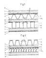
- Fig. 1 shows a schematic section / elevation through a fuel cell arrangement with a separating plate and on both sides of it laterally freely movable current collectors in the form of corrugated bands.
- the actual high-temperature fuel cell consists of the ceramic solid electrolyte 1 made of doped, stabilized ZrO2 and the porous (positive ) Oxygen electrode 2 (La / Mn perovskite) and the porous (negative) fuel electrode 3 (Ni / ZrO2 cermet).
- 4 is a nickel mesh (wire mesh, felt, fleece, metal wool, etc.) sintered, welded or soldered onto the fuel electrode 3.
- 5 shows the current collector on the fuel side in the form of a trapezoidal corrugated band, which preferably consists of Ni.
- the separating plate 7 represents a gas-tight, electrically conductive separating plate made of an oxidation-resistant high-temperature alloy. In principle, nickel, cobalt or iron alloys are possible.
- the separating plate 7 has a nickel plating 8 on the fuel side as a contact-imparting surface layer for sliding contact with the fuel-side current collector 5.
- the lateral free mobility parallel to the plane of the plate, which is made possible for the latter, is indicated by a double arrow.
- 9 represents a thin noble metal plating on the oxygen side of the separating plate 7. It generally consists of Au, a Pt metal or a corresponding alloy.
- the current collector 10 is the current collector on the oxygen side in the form of a rectangular corrugated band, which is generally made of a heat-resistant nickel or iron alloy.
- a noble metal coating 11 consisting of a Pt metal.
- the lateral free mobility parallel to the plane of the plate is indicated by a double arrow.
- the current collector 10 is fixed on the oxygen side and is electrically conductively embedded in the oxygen electrode 2.
- the symbol CH4 generally stands for the space flooded by the gaseous fuel, the symbol O2 for the space flooded by the gaseous oxygen carrier (air) of the fuel cell.
- FIG. 2 shows a schematic section / elevation through a fuel cell arrangement with a separating plate and current collectors made of band-shaped or wire-shaped components that are freely movable laterally on both sides thereof.
- the reference numerals 1 to 11 correspond to those in FIG. 1.
- the current collector 10 on the oxygen side here has the shape of a trapezoidal corrugated band.
- the apexes of the shaft, which face the separating plate and which carry the noble metal coating 11 on their contact surfaces with the noble metal coating 11, are embodied further than the opposite apexes embedded in the oxygen electrode 2.
- the current collector 5 on the fuel side is in the form of a relatively loose coil, the turns of which are slightly crooked to the longitudinal axis.
- the lateral free mobility of the current collectors 5 and 10 parallel to the plate plane is again indicated by a double arrow.
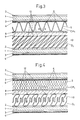
- FIG. 3 relates to a schematic section / elevation through a fuel cell arrangement with a separating plate and a wire-shaped current collector firmly anchored on the oxygen side both in the separating plate and in the oxygen electrode.
- the reference numerals 1 to 8 are correspondingly accurate 1.
- the noble metal plating 9 on the oxygen side of the separating plate 7 is missing.
- the noble metal coating 11 on the contact / contact surface of the oxygen-side current collector 10 is missing. Instead, the latter is firmly mechanically non-positive and electrically conductive via point-like soldered or welded connections 12 anchored on the partition plate 7.
- the current collector 10 here has the shape of a thin-wire coil with flattened turns that are very slanted with respect to the longitudinal axis of the helix, which is totally clamped both on the side of the separating plate 7 (point connections 12) and on the side of the oxygen electrode 2 (embedding).
- the wire diameter of the current collector 10 is shown exaggerated in the figure.
- the current collector 5 on the fuel side is in the form of a thin sinusoidal corrugated band. Its lateral mobility parallel to the plane of the plate is indicated by a double arrow.
- FIG. 4 shows a schematic section / elevation through a fuel cell arrangement with a separating plate and on the oxygen side firmly anchored in the form of a multiply corrugated current collector both in the separating plate and in the oxygen electrode.
- the current collector 5 on the fuel side is in the form of a loose metal wool or a metal knitted fabric and is firmly united to the nickel fabric 4 by means of punctiform soldered connections.
- the lateral mobility of individual wave-like parts of the current collector 5 is indicated by a double arrow.
- the current collector 10 on the oxygen side is designed in the form of a double corrugated thin band.
- a sinusoidal, oblique main shaft is superimposed by a secondary wave of smaller amplitude and smaller wavelength in the area of the zero crossing.
- a component arrangement for power supply was constructed from the following individual parts: Nickel mesh on the fuel electrode current collector, fuel side separating plate current collector, oxygen side
- the actual fuel cell consisted of a flat, flat plate with the centrally located solid electrolyte 1 made of stabilized ZrO2, a sintered oxygen electrode 2 made of La / Mn perovskite and a sintered fuel electrode 3 made of a Ni / ZrO2 cermet.
- a nickel fabric 4 (wire diameter 0.03 mm; mesh size 0.25 mm) was sintered onto the latter over a large area with the aid of a sintering additive lowering the melting point.
- the current collector 5 was combined with the nickel fabric 4 at the apexes of one side via point-shaped solder connections 6 to form a unitary whole.
- a nickel solder with small additions of Ag, Cr and Si was used, the melting point of which was approx. 100 ° C below that of pure nickel.
- This carrier material of the partition plate 7 was electrochemically provided with a 30 ⁇ m thick nickel plating 8 on the fuel side. On the oxygen side in the same way, a noble metal plating 9 in the form of an Au layer 5 ⁇ m thick is applied galvanically.
- the oxygen-side current collector 10 consisted of a rectangular corrugated band, which was additionally finely corrugated in the vertical parts (webs).
- the current collector 10 was provided with a noble metal coating 11 in the form of a Pt coating of 3 ⁇ m thickness on the flat, parting faces of the rectangular shaft facing the partition plate 7. This layer was applied electrochemically after gold plating was 0.5 ⁇ m thick.
- the precious metal coating 11 ensures a perfect current transfer at the contact / contact surface of the current collector / separating plate during operation.
- the roughened flat apex of the current collector facing the oxygen electrode 2 tors 10 were embedded or sintered on in the La / Mn perovskite of the electrode, suitable sintering additives and a reducing to neutral sintering atmosphere being selected.
- the current collectors 5 and 10 had little deflection in the direction perpendicular to the plate plane, but were generally relatively stiff while sliding freely on the separating plate 7 in the lateral direction parallel to the plate plane could move.
- the structure of the component arrangement for current conduction was basically the same as in Example 1.
- the nickel fabric 4 consisted of more or less matted, very thin wires and was sintered onto the fuel electrode 3 over a large area as in Example 1.
- the current collector was put together as a whole at the relevant vertices of the windings via point-shaped solder connections 6 with the nickel fabric (felt).
- the carrier material of this separating plate 7 was electrochemically provided with a 40 ⁇ m thick nickel plating 8 on the fuel side.
- a noble metal plating 9 in the form of an Au / Pd alloy with 20% by weight of Pd was applied electrochemically on the oxygen side by successively depositing several Au and Pd layers and then doing the whole thing for 1/2 h at 900 ° C. by diffusion annealing was subjected to vacuum.
- the finished precious metal plating had a layer thickness of 6 ⁇ m.
- the advantage of this Au / Pd alloy is that the melting point (solidus temperature) is about 300 ° C higher than that of pure Au.
- the current collector 10 was provided with a noble metal coating 11 in the form of a Pt / Pd overlay of 5 ⁇ m thick on the flat tops of the trapezoidal shaft facing the partition plate 7.
- the Pt / Pd alloy contained 50% by weight of Pt and 50% by weight of Pd and was electrochemically deposited after the previous gold plating was 0.5 ⁇ m thick.
- the narrow flat vertices of the current collector 10 facing the oxygen electrode 2 were embedded in the La / Mn perovskite of the electrode and firmly anchored by sintering.
- the current collector 10 was comparatively stiff in the direction perpendicular to the plate plane, while the current collector 5 deflected relatively strongly under the load. Both current collectors could move freely on the partition plate 7 laterally parallel to the plane of the plate.
- the structure of the component arrangement was similar to that in Example 1, but the current collector 10 was anchored on the oxygen side both in the oxygen electrode 2 and on the separating plate 7.
- the nickel fabric 4 consisted of a structure similar to wire mesh and of similar dimensions as in Example 1. It was sintered over a large area on the fuel electrode 3.
- the current collector 5 was connected to the nickel fabric 4 at the vertices of one side via point-shaped solder connections 6.
- the carrier material of the separating plate 7 was electrochemically provided with a 35 ⁇ m thick nickel plating 8 on the fuel side.
- the oxygen side remained unchanged, i.e. without plating.
- it was cleaned, stained and polished to a high gloss before further processing.
- the oxygen-side current collector 10 consisted of a thin-stranded helix with flattened turns that were very crooked to the longitudinal axis of the helix.
- the winding is inclined at approximately 45 ° to the normal plane
- the current collector 10 was anchored in an electrically conductive and mechanically non-positive manner at the apices of the windings facing the separating plate 7 by spot welds 12 with the separating plate 7.
- the crests of the turns facing the oxygen electrode 2 were embedded in the La / Mn perovskite of the electrode and fastened by sintering. Thanks to the inclination of the turns of the filament, the current collector 10 was remarkably elastic both in the direction perpendicular to the plate plane and parallel to the latter, despite being clamped in on both sides. Since a contact pressure for good current transmission is not necessary either on the oxygen electrode 2 or on the separating plate 7, the spring constant of the current collector 10 can be as small as desired.
- the structure of the component arrangement for current conduction was basically the same as in Example 3.
- the nickel fabric 4 consisted of a felt-like or metal-wool-like fleece and was sintered onto the fuel electrode 3 over a large area analogously to Example 1 (diffusion welding).
- the current collector 5 was connected to the nickel fabric 4 at numerous points of contact via point-shaped solder connections using a well-wetting nickel solder with a melting point of approximately 1300 ° C.
- the carrier material of the separating plate 7 was galvanically provided with a 25 ⁇ m thick nickel plating 8 on the fuel side.
- the oxygen side remained unchanged.
- the oxygen-side current collector 10 consisted of a double corrugated thin band.
- a sinusoidal, oblique main wave was a secondary wave of smaller amplitude and shorter wavelength in the area of the zero crossing overlaid.
- the current collector 10 was electrically conductively connected to the separating plate 7 at the apexes of the main shaft facing the separating plate 7 by punctiform Ni / Cr soldered connections 12.
- the crests of the main shaft facing the oxygen electrode 2 were embedded in the La / Mn perovskite of the electrode and firmly anchored. Thanks to the double-shaft design, the current collector was very elastic in both main directions (perpendicular to the plate plane and parallel to it). The statements made in Example 3 apply.
- the noble metal coatings plat 9 on the oxygen side of the separating plate 7; coating 11 on the contact / contact surface of the current collector 10 with the separating plate 7
- Such barrier layers are generally applied by flame spraying, plasma spraying, in rare cases (because expensive!) By sputtering onto the carrier metal.
- a nickel silicide was preferably used for this purpose.
- the invention is not restricted to the exemplary embodiments.
- the component arrangement for current flow between adjacent flat, flat, stacked high-temperature fuel cells with solid electrolyte 1 on the basis of doped, stabilized zirconium oxide, the oxygen electrode 2 of one fuel cell being electrically connected to the fuel electrode 3 of the next fuel cell and that between the electrodes 2 ; 3 lying space is divided by a gas-tight, electrically conductive partition plate 7 into two, the different gaseous media fuel CH4 and oxygen carrier O2 leading spaces, generally consists in that a flat smooth partition plate 7 and arranged on both sides of it, both in the oxygen electrode 2 and also in the fuel electrode 3 firmly anchored current collectors 5; 10 are present, with at least the current collector being designed to slide freely on the side of the partition plate 7 laterally parallel to the plane of the plate.
- the component arrangement preferably consists of the separating plate 7 made of a heat-resistant high-temperature alloy which is clad on the oxygen side with a noble metal 9 or a noble metal alloy and on the fuel side with nickel 8 or a high-proof nickel alloy, the current collector 10 on the oxygen side being made of an oxidation-resistant there is a heat-resistant alloy, which is coated at least at the points of contact with the separating plate 7 with a noble metal 11 and is firmly embedded on its opposite side in the oxygen electrode 2 made of La / Mn perovskite and that the current collector 5 on the fuel side is made of nickel or a consists of high-percentage nickel alloy and is firmly connected via a nickel fabric 4 by a solder, weld or sinter connection 6 with the fuel electrode 3 consisting of a Ni / ZrO2 cermet.
- the current collector 10 is firmly connected on the oxygen side to the separating plate via the contact points coated with noble metal by means of a soldered, welded or sintered connection 12.
- the component arrangement advantageously consists in that the current collector 10 on the oxygen side consists of a carrier made of an iron-based or a nickel-based superalloy with or without dispersion hardening and that at least that with a noble metal, selected from the group Au, Pd, Pt, Rh or an alloy at least two of these elements, coated locations between the carrier metal and the noble metal coating 9 have a diffusion barrier layer based on a silicon-containing intermetallic compound.
- the current collectors 5; 10 have the form of single or multiple corrugated, kinked or pleated tapes or of wire coils, wire mesh, metal fabrics or of metal felts or nonwovens.
Landscapes
- Life Sciences & Earth Sciences (AREA)
- Engineering & Computer Science (AREA)
- Manufacturing & Machinery (AREA)
- Sustainable Development (AREA)
- Sustainable Energy (AREA)
- Chemical & Material Sciences (AREA)
- Chemical Kinetics & Catalysis (AREA)
- Electrochemistry (AREA)
- General Chemical & Material Sciences (AREA)
- Fuel Cell (AREA)
Applications Claiming Priority (2)
| Application Number | Priority Date | Filing Date | Title |
|---|---|---|---|
| CH373089 | 1989-10-12 | ||
| CH3730/89 | 1989-10-12 |
Publications (1)
| Publication Number | Publication Date |
|---|---|
| EP0432381A1 true EP0432381A1 (fr) | 1991-06-19 |
Family
ID=4262272
Family Applications (1)
| Application Number | Title | Priority Date | Filing Date |
|---|---|---|---|
| EP90117576A Withdrawn EP0432381A1 (fr) | 1989-10-12 | 1990-09-12 | Disposition d'éléments de construction pour conduire le courant entre des cellules à combustible céramiques fonctionnant à haute température |
Country Status (2)
| Country | Link |
|---|---|
| EP (1) | EP0432381A1 (fr) |
| JP (1) | JPH03184268A (fr) |
Cited By (19)
| Publication number | Priority date | Publication date | Assignee | Title |
|---|---|---|---|---|
| CH679620A5 (fr) * | 1990-12-11 | 1992-03-13 | Sulzer Ag | |
| DE19517451A1 (de) * | 1995-05-12 | 1996-05-23 | Mtu Friedrichshafen Gmbh | Brennstoffzellenanordnung mit Stromkollektor aus Drahtgewebematerial |
| DE19517443A1 (de) * | 1995-05-12 | 1996-11-14 | Mtu Friedrichshafen Gmbh | Korrosionsbeständiger Stromkollektor und Verfahren zur Herstellung eines solchen |
| WO1997030485A1 (fr) * | 1996-02-12 | 1997-08-21 | Siemens Aktiengesellschaft | Cellule electrochimique haute temperature et empilement de cellules electrochimiques a structures conductrices composites metalliques |
| EP0840388A1 (fr) * | 1996-10-30 | 1998-05-06 | Sulzer Hexis AG | Batterie de piles à combustible de type plan fonctionnant à haute température |
| WO1998025316A1 (fr) * | 1996-12-06 | 1998-06-11 | Forschungszentrum Jülich GmbH | Materiau pour interconnecteurs d'elements combustibles |
| WO1998036464A1 (fr) * | 1997-02-15 | 1998-08-20 | Forschungszentrum Jülich GmbH | Interconnecteur pour piles a combustible sofc empilees |
| WO2002101859A3 (fr) * | 2001-06-13 | 2003-05-08 | Bayerische Motoren Werke Ag | Pile a combustible et procede de fabrication associe |
| EP1328030A1 (fr) * | 2002-01-15 | 2003-07-16 | N.V. Bekaert S.A. | Empilement d'éléments métalliques pour piles à combustible et électrolyseurs |
| WO2004030133A1 (fr) * | 2002-09-27 | 2004-04-08 | Stichting Energieonderzoek Centrum Nederland | Pile a combustible supportee par une electrode |
| US7144649B2 (en) * | 2002-11-27 | 2006-12-05 | Utc Fuel Cells, Llc | Interconnect for solid oxide fuel cells |
| EP1284510A3 (fr) * | 2001-08-18 | 2006-12-27 | ElringKlinger AG | Méthode de fabrication d'un substrat pour une électrode d'une unité de pile à combustible et un substrat ainsi fabriqué |
| EP1501142A3 (fr) * | 2003-07-24 | 2007-02-28 | Nissan Motor Co., Ltd. | Structure collectrice pour piles à combustible et assemblage de piles à combustible à oxyde solide comprenant celle-ci |
| WO2006122534A3 (fr) * | 2005-05-18 | 2007-06-21 | Staxera Gmbh | Empilement de piles a combustible a oxyde solide |
| US7449261B2 (en) | 2001-09-13 | 2008-11-11 | Ngk Insulators, Ltd. | Holding member for holding an electrochemical cell, a holding substrate for the same, an electrochemical system and a connecting member for electrochemical cells |
| DE10317388B4 (de) * | 2003-04-15 | 2009-06-10 | Bayerische Motoren Werke Aktiengesellschaft | Brennstoffzelle und/oder Elektrolyseur sowie Verfahren zu deren/dessen Herstellung |
| DE102009051890A1 (de) | 2009-11-04 | 2011-05-05 | Mtu Onsite Energy Gmbh | Stromkollektor, insbesondere Anodenstromkollektor für eine Brennstoffzelle |
| EP1595304A4 (fr) * | 2003-01-31 | 2012-02-15 | Utc Fuel Cells Llc | Interconnexions compliantes, resistant aux contraintes pour empilement de pile a combustible a oxyde solide |
| DE102024209735A1 (de) * | 2024-10-07 | 2026-04-09 | Robert Bosch Gesellschaft mit beschränkter Haftung | Verfahren zur Herstellung eines elektrochemischen Zellenelements, elektrochemisches Zellenelements, elektrochemische Zellenvorrichtung |
Families Citing this family (11)
| Publication number | Priority date | Publication date | Assignee | Title |
|---|---|---|---|---|
| JP4646102B2 (ja) * | 2003-04-16 | 2011-03-09 | 日本特殊陶業株式会社 | 固体電解質型燃料電池 |
| JP4949834B2 (ja) * | 2003-07-18 | 2012-06-13 | ヴァーサ パワー システムズ リミテッド | 燃料電池スタック |
| JP5035571B2 (ja) * | 2003-07-24 | 2012-09-26 | 日産自動車株式会社 | 燃料電池用集電構造及び固体酸化物形燃料電池スタック |
| JP4666279B2 (ja) * | 2004-06-22 | 2011-04-06 | 日産自動車株式会社 | 固体酸化物形燃料電池スタック及び固体酸化物形燃料電池 |
| US7190568B2 (en) * | 2004-11-16 | 2007-03-13 | Versa Power Systems Ltd. | Electrically conductive fuel cell contact materials |
| EP1897162A1 (fr) * | 2005-06-15 | 2008-03-12 | ATI Properties, Inc. | Interconnexions pour piles a oxyde solide et acier ferritique conçu pour etre utilise avec les piles a oxyde solide |
| JP4889319B2 (ja) * | 2006-02-24 | 2012-03-07 | 京セラ株式会社 | 燃料電池セルスタック及び集電部材 |
| JP2008243572A (ja) * | 2007-03-27 | 2008-10-09 | Equos Research Co Ltd | 集電体及び燃料電池 |
| JP5246532B2 (ja) * | 2007-08-30 | 2013-07-24 | 日産自動車株式会社 | 燃料電池 |
| JP5504615B2 (ja) * | 2008-11-28 | 2014-05-28 | 日産自動車株式会社 | 固体高分子形燃料電池 |
| JP5607561B2 (ja) * | 2011-03-11 | 2014-10-15 | 日本特殊陶業株式会社 | 固体酸化物形燃料電池 |
Citations (6)
| Publication number | Priority date | Publication date | Assignee | Title |
|---|---|---|---|---|
| US3300344A (en) * | 1962-06-27 | 1967-01-24 | Gen Dynamics Corp | Fuel cell having zirconia-containing electrolyte and ceramic electrodes |
| CH490742A (de) * | 1968-01-31 | 1970-05-15 | Bbc Brown Boveri & Cie | Batterie aus Brennstoffzellen mit Festelektrolyt |
| FR2296703A1 (fr) * | 1974-12-31 | 1976-07-30 | Commissariat Energie Atomique | Cellule d'electrolyse de la vapeur d'eau a haute temperature |
| JPS6124158A (ja) * | 1984-07-13 | 1986-02-01 | Mitsubishi Electric Corp | 溶融炭酸塩形燃料電池の電極 |
| JPS61109262A (ja) * | 1984-11-01 | 1986-05-27 | Hitachi Ltd | 燃料電池 |
| JPS61279068A (ja) * | 1985-06-05 | 1986-12-09 | Ishikawajima Harima Heavy Ind Co Ltd | 溶融炭酸塩燃料電池 |
-
1990
- 1990-09-12 EP EP90117576A patent/EP0432381A1/fr not_active Withdrawn
- 1990-10-12 JP JP2275161A patent/JPH03184268A/ja active Pending
Patent Citations (6)
| Publication number | Priority date | Publication date | Assignee | Title |
|---|---|---|---|---|
| US3300344A (en) * | 1962-06-27 | 1967-01-24 | Gen Dynamics Corp | Fuel cell having zirconia-containing electrolyte and ceramic electrodes |
| CH490742A (de) * | 1968-01-31 | 1970-05-15 | Bbc Brown Boveri & Cie | Batterie aus Brennstoffzellen mit Festelektrolyt |
| FR2296703A1 (fr) * | 1974-12-31 | 1976-07-30 | Commissariat Energie Atomique | Cellule d'electrolyse de la vapeur d'eau a haute temperature |
| JPS6124158A (ja) * | 1984-07-13 | 1986-02-01 | Mitsubishi Electric Corp | 溶融炭酸塩形燃料電池の電極 |
| JPS61109262A (ja) * | 1984-11-01 | 1986-05-27 | Hitachi Ltd | 燃料電池 |
| JPS61279068A (ja) * | 1985-06-05 | 1986-12-09 | Ishikawajima Harima Heavy Ind Co Ltd | 溶融炭酸塩燃料電池 |
Non-Patent Citations (3)
| Title |
|---|
| PATENT ABSTRACTS OF JAPAN, Band 10, Nr. 175 (E-413)[2231], 20. Juni 1986; & JP-A-61 24 158 (MITSUBISHI DENKI K.K.) 01-02-1986 * |
| PATENT ABSTRACTS OF JAPAN, Band 10, Nr. 289 (E-442)[2345], 2. Oktober 1986; & JP-A-61 109 262 (HITACHI LTD) 27-05-1986 * |
| PATENT ABSTRACTS OF JAPAN, Band 11, Nr. 138 (E-503)[2585], 2. Mai 1987; & JP-A-61 279 068 (ISHIKAWAJIMA HARIMA HEAVY IND. CO., LTD) 09-12-1986 * |
Cited By (27)
| Publication number | Priority date | Publication date | Assignee | Title |
|---|---|---|---|---|
| EP0490808A1 (fr) * | 1990-12-11 | 1992-06-17 | Sulzer Innotec Ag | Module pour une pile à combustible |
| CH679620A5 (fr) * | 1990-12-11 | 1992-03-13 | Sulzer Ag | |
| DE19517451A1 (de) * | 1995-05-12 | 1996-05-23 | Mtu Friedrichshafen Gmbh | Brennstoffzellenanordnung mit Stromkollektor aus Drahtgewebematerial |
| DE19517443A1 (de) * | 1995-05-12 | 1996-11-14 | Mtu Friedrichshafen Gmbh | Korrosionsbeständiger Stromkollektor und Verfahren zur Herstellung eines solchen |
| WO1997030485A1 (fr) * | 1996-02-12 | 1997-08-21 | Siemens Aktiengesellschaft | Cellule electrochimique haute temperature et empilement de cellules electrochimiques a structures conductrices composites metalliques |
| US5902692A (en) * | 1996-10-30 | 1999-05-11 | Sulzer Hexis Ag | Battery with planar high temperature fuel cells |
| EP0840388A1 (fr) * | 1996-10-30 | 1998-05-06 | Sulzer Hexis AG | Batterie de piles à combustible de type plan fonctionnant à haute température |
| WO1998025316A1 (fr) * | 1996-12-06 | 1998-06-11 | Forschungszentrum Jülich GmbH | Materiau pour interconnecteurs d'elements combustibles |
| WO1998036464A1 (fr) * | 1997-02-15 | 1998-08-20 | Forschungszentrum Jülich GmbH | Interconnecteur pour piles a combustible sofc empilees |
| US6268076B1 (en) | 1997-02-15 | 2001-07-31 | Forschungszentrum Jülich GmbH | Current collector for a SOFC fuel-cell pile |
| WO2002101859A3 (fr) * | 2001-06-13 | 2003-05-08 | Bayerische Motoren Werke Ag | Pile a combustible et procede de fabrication associe |
| EP1284510A3 (fr) * | 2001-08-18 | 2006-12-27 | ElringKlinger AG | Méthode de fabrication d'un substrat pour une électrode d'une unité de pile à combustible et un substrat ainsi fabriqué |
| EP1986256A1 (fr) * | 2001-08-18 | 2008-10-29 | ElringKlinger AG | Méthode de fabrication d'un substrat pour une électrode d'une unité de pile à combustible et un substrat ainsi fabriqué |
| US7449261B2 (en) | 2001-09-13 | 2008-11-11 | Ngk Insulators, Ltd. | Holding member for holding an electrochemical cell, a holding substrate for the same, an electrochemical system and a connecting member for electrochemical cells |
| WO2003061042A3 (fr) * | 2002-01-15 | 2003-10-23 | Bekaert Sa Nv | Empilement de metal destine a des piles a combustible ou a des electrolyseurs |
| CN1316660C (zh) * | 2002-01-15 | 2007-05-16 | 贝卡尔特股份有限公司 | 用于燃料电池或者电解槽的金属叠板,包括这种叠板的燃料电池或者电解槽,以及这种叠板在燃料电池或者电解槽中的应用 |
| EP1328030A1 (fr) * | 2002-01-15 | 2003-07-16 | N.V. Bekaert S.A. | Empilement d'éléments métalliques pour piles à combustible et électrolyseurs |
| NL1021547C2 (nl) * | 2002-09-27 | 2004-04-20 | Stichting Energie | Elektrode gedragen brandstofcel. |
| WO2004030133A1 (fr) * | 2002-09-27 | 2004-04-08 | Stichting Energieonderzoek Centrum Nederland | Pile a combustible supportee par une electrode |
| US7144649B2 (en) * | 2002-11-27 | 2006-12-05 | Utc Fuel Cells, Llc | Interconnect for solid oxide fuel cells |
| EP1595304A4 (fr) * | 2003-01-31 | 2012-02-15 | Utc Fuel Cells Llc | Interconnexions compliantes, resistant aux contraintes pour empilement de pile a combustible a oxyde solide |
| DE10317388B4 (de) * | 2003-04-15 | 2009-06-10 | Bayerische Motoren Werke Aktiengesellschaft | Brennstoffzelle und/oder Elektrolyseur sowie Verfahren zu deren/dessen Herstellung |
| EP1501142A3 (fr) * | 2003-07-24 | 2007-02-28 | Nissan Motor Co., Ltd. | Structure collectrice pour piles à combustible et assemblage de piles à combustible à oxyde solide comprenant celle-ci |
| US7338729B2 (en) | 2003-07-24 | 2008-03-04 | Nissan Motor Co., Ltd. | Fuel cell collector structure and solid oxide fuel cell stack using the same |
| WO2006122534A3 (fr) * | 2005-05-18 | 2007-06-21 | Staxera Gmbh | Empilement de piles a combustible a oxyde solide |
| DE102009051890A1 (de) | 2009-11-04 | 2011-05-05 | Mtu Onsite Energy Gmbh | Stromkollektor, insbesondere Anodenstromkollektor für eine Brennstoffzelle |
| DE102024209735A1 (de) * | 2024-10-07 | 2026-04-09 | Robert Bosch Gesellschaft mit beschränkter Haftung | Verfahren zur Herstellung eines elektrochemischen Zellenelements, elektrochemisches Zellenelements, elektrochemische Zellenvorrichtung |
Also Published As
| Publication number | Publication date |
|---|---|
| JPH03184268A (ja) | 1991-08-12 |
Similar Documents
| Publication | Publication Date | Title |
|---|---|---|
| EP0424732A1 (fr) | Elément de conduction du courant pour des cellules à combustible empilées fonctionnant à haute température et sa méthode de fabrication | |
| DE69838679T2 (de) | Elektrische leitfähigkeit in einer brennstoffzellen-anordnung | |
| DE19681750B4 (de) | Elektrische Verbindungsvorrichtung für eine planare Brennstoffzelle und deren Verwendung | |
| DE4016157A1 (de) | Vorrichtung zur umwandlung von chemischer energie in elektrische energie mittels in serie geschalteter flacher, ebener hochtemperatur-brennstoffzellen | |
| EP0446680A1 (fr) | Collecteur de courant pour l'amenée du courant entre des cellules à combustible voisines empilées fonctionnant à haute température | |
| EP0960447B1 (fr) | Interconnecteur pour piles a combustible sofc empilees | |
| EP0378812A1 (fr) | Agencement de cellules à combustible à base d'un électrolyte solide constitué d'oxyde de zircon stabilisé fonctionnant à haute température pour obtenir une puissance maximale | |
| JPH03184268A (ja) | セラミック高温燃料電池の電流伝導のための部品配置 | |
| EP0410159A1 (fr) | Collecteur de courant pour pile à combustible fonctionnant à haute température | |
| EP1314217B1 (fr) | Pile a combustible haute temperature | |
| EP0578855A1 (fr) | Matériau pour les composants métalliques de dispositifs de piles à combustible fonctionnant à haute température | |
| EP0424691A1 (fr) | Disposition d'éléments de construction pour conduire le courant entre des cellules à combustible céramiques fonctionnant à haute température | |
| EP0410166A1 (fr) | Elément de construction pour la conduction du courant pour piles à combustibles fonctionnant à haute température | |
| EP0423448A1 (fr) | Collecteur pour la conduction du courant entre des cellules à combustible arrangées selon une pile et fonctionnant à haute température et méthode de fabrication | |
| EP0840947A1 (fr) | Pile a combustible pour hautes temperatures et empilement de piles pour hautes temperatures pourvu de plaquettes conductrices d'interconnexion portant une couche de contact en spinelle au chrome | |
| EP0418528A1 (fr) | Collecteur de courant pour cellules à combustible céramiques | |
| DE102014118358A1 (de) | Einzelzelle mit angebrachtem Separator und Brennstoffzellenstapel, undVerfahren zur Herstellung einer Einzelzelle mit angebrachtem Separator | |
| EP1287572B1 (fr) | Dispositif de mise en contact electrique d'electrodes dans des cellules a combustible haute temperature | |
| DE4307666C1 (de) | Stromanschlußelement für Festelektrolyt-Brennstoffzellen, Verfahren zu seiner Herstellung und dessen Verwendung | |
| EP0440968A1 (fr) | Elément pour l'obtention d'une distribution aussi uniforme que possible sur la surface d'une cellule à combustible céramique en forme de plaques fonctionnant à haute température | |
| WO2000010214A2 (fr) | Pile a combustible haute temperature pourvue d'un reseau de nickel, et empilement de piles a combustible haute temperature comportant de telles piles | |
| DE102005014077A1 (de) | Interkonnenktor für Hochtemperaturbrennstoffzellen | |
| DE19718687C2 (de) | Brennstoffzellenanordnung zur Erhöhung der Spannung | |
| EP0411374A1 (fr) | Elément de conduction du courant pour piles à combustible en matière céramique fonctionnant à haute température | |
| DE19808859C2 (de) | Brennstoffzellenstapel mit Stromleiter |
Legal Events
| Date | Code | Title | Description |
|---|---|---|---|
| PUAI | Public reference made under article 153(3) epc to a published international application that has entered the european phase |
Free format text: ORIGINAL CODE: 0009012 |
|
| AK | Designated contracting states |
Kind code of ref document: A1 Designated state(s): CH DE FR GB IT LI NL SE |
|
| STAA | Information on the status of an ep patent application or granted ep patent |
Free format text: STATUS: THE APPLICATION IS DEEMED TO BE WITHDRAWN |
|
| 18D | Application deemed to be withdrawn |
Effective date: 19911220 |