EP0410173A2 - Machine à rainurer - Google Patents
Machine à rainurer Download PDFInfo
- Publication number
- EP0410173A2 EP0410173A2 EP90112827A EP90112827A EP0410173A2 EP 0410173 A2 EP0410173 A2 EP 0410173A2 EP 90112827 A EP90112827 A EP 90112827A EP 90112827 A EP90112827 A EP 90112827A EP 0410173 A2 EP0410173 A2 EP 0410173A2
- Authority
- EP
- European Patent Office
- Prior art keywords
- frame
- feed
- support plane
- clamping jaws
- profiling
- Prior art date
- Legal status (The legal status is an assumption and is not a legal conclusion. Google has not performed a legal analysis and makes no representation as to the accuracy of the status listed.)
- Withdrawn
Links
- 239000002023 wood Substances 0.000 claims abstract description 3
- 238000003801 milling Methods 0.000 description 10
- 238000003754 machining Methods 0.000 description 4
- 230000001360 synchronised effect Effects 0.000 description 1
- 238000011144 upstream manufacturing Methods 0.000 description 1
Images

Classifications
-
- B—PERFORMING OPERATIONS; TRANSPORTING
- B27—WORKING OR PRESERVING WOOD OR SIMILAR MATERIAL; NAILING OR STAPLING MACHINES IN GENERAL
- B27G—ACCESSORY MACHINES OR APPARATUS FOR WORKING WOOD OR SIMILAR MATERIALS; TOOLS FOR WORKING WOOD OR SIMILAR MATERIALS; SAFETY DEVICES FOR WOOD WORKING MACHINES OR TOOLS
- B27G19/00—Safety guards or devices specially adapted for wood saws; Auxiliary devices facilitating proper operation of wood saws
- B27G19/10—Measures preventing splintering of sawn portions of wood
-
- B—PERFORMING OPERATIONS; TRANSPORTING
- B27—WORKING OR PRESERVING WOOD OR SIMILAR MATERIAL; NAILING OR STAPLING MACHINES IN GENERAL
- B27C—PLANING, DRILLING, MILLING, TURNING OR UNIVERSAL MACHINES FOR WOOD OR SIMILAR MATERIAL
- B27C5/00—Machines designed for producing special profiles or shaped work, e.g. by rotary cutters; Equipment therefor
- B27C5/02—Machines with table
- B27C5/06—Arrangements for clamping or feeding work
-
- B—PERFORMING OPERATIONS; TRANSPORTING
- B27—WORKING OR PRESERVING WOOD OR SIMILAR MATERIAL; NAILING OR STAPLING MACHINES IN GENERAL
- B27F—DOVETAILED WORK; TENONS; SLOTTING MACHINES FOR WOOD OR SIMILAR MATERIAL; NAILING OR STAPLING MACHINES
- B27F1/00—Dovetailed work; Tenons; Making tongues or grooves; Groove- and- tongue jointed work; Finger- joints
- B27F1/02—Making tongues or grooves, of indefinite length
Definitions
- the innovation concerns a folding machine for milling the outer sides of frames made of wood, in particular window frames.
- the workpiece slides on a support table and is guided past milling tools along a guide stop provided in the region of the latter by driven feed rollers at the top.
- the feed rollers are usually positioned slightly obliquely against the guide stop.
- a milling unit working in synchronism and controllable at the end of the frame sides prevents tears on the cross-timber sections.
- the machining distance is as short as possible, and the milling spindles are usually one above the other for holding several tools that can be used optionally.
- the workpiece is guided past the milling tools by an underlying feed chain provided with coated support plates.
- Pressure rollers on the top provide the necessary contact pressure.
- the inclined feed rollers press the beginning of the workpiece into the relatively large gap in the guide stop created by the sum of the superimposed milling tools. This rotation of the frame is supported when the synchronous milling unit is used at about the same time.
- clamping the frame on a cross leg by means of clamping jaws which can be controlled independently of one another perpendicularly to the frame support and which can move along a guide parallel to the guide stop and which can be returned to their basic position by means of a pressure-actuated cylinder after loosening and actuation.
- At least two longitudinal profiling spindles (1), (2) are provided in a rebounding machine, one of which works in synchronism and at the end of the respectively machined side (3a) of the frame (3) in the direction of the arrow (4) to avoid this is controlled by tears in the transverse timber.
- the frame is advanced in the direction of arrow (8) by feed rollers (5), which in this version are mounted in drive gears (6).
- feed rollers and a drive gear form a feed group (7).
- the frame slides on the support table (9) and along the guide stop (10).
- the feed groups are fastened to a continuous support in a manner not shown and are jointly adjustable at workpiece height.
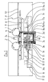
- the tensioning device (11) is also fastened to this carrier in a manner not shown in detail.
- It consists of a carrier (12) with a guide (13) parallel to the support table and the guide stop, in which two guide carriages (14) and (14a) are mounted so as to be longitudinally movable. These are as Angle formed and take perpendicular to the support table (9) extending guide rails (15) or (15a), in which the clamping jaws (16) or (16a) are mounted for height actuation by the pressure-actuated cylinders (17) or (17a) . The clamping jaws are opened and closed by the pressure-actuated cylinder (18).
- clamping jaws (16), (16a) are indicated in their open and open positions in their basic and end positions.
- the guide carriage (14) is coupled to a pressure-actuated cylinder (19), which ensures that the guide carriage is returned to the basic position.
- the operation of the machine in this embodiment is as follows: the feed rollers in the area of the basic position of the clamping jaws are raised, likewise the clamping jaw (16a), while the clamping jaw (16) is controlled downwards.
- the frame is placed on the support table (9) and against the guide stop (10) and advanced in the direction of arrow (8) under the raised feed rollers (5) until the frame side (3b) abuts the clamping jaw (16).
- both the clamping jaw (16a) and the running feed rollers (5) are controlled downwards.
- the clamping jaw (16a) is in its lower end position, the clamping cylinder (18) is closed.
- the frame is guided past the milling tools in a known manner by a feed chain located at the bottom, provided with support plates, under the contact pressure of pressure rollers located at the top.
- the frame is aligned on a support table upstream of the feed mechanism and, as described in the first embodiment, clamped before it is fed to the feed, for example with the aid of the reversed cylinder (19).
Landscapes
- Life Sciences & Earth Sciences (AREA)
- Engineering & Computer Science (AREA)
- Mechanical Engineering (AREA)
- Wood Science & Technology (AREA)
- Forests & Forestry (AREA)
- Jigs For Machine Tools (AREA)
Applications Claiming Priority (2)
| Application Number | Priority Date | Filing Date | Title |
|---|---|---|---|
| DE19893924307 DE3924307A1 (de) | 1989-07-22 | 1989-07-22 | Umfaelzmaschine |
| DE3924307 | 1989-07-22 |
Publications (2)
| Publication Number | Publication Date |
|---|---|
| EP0410173A2 true EP0410173A2 (fr) | 1991-01-30 |
| EP0410173A3 EP0410173A3 (en) | 1991-07-10 |
Family
ID=6385624
Family Applications (1)
| Application Number | Title | Priority Date | Filing Date |
|---|---|---|---|
| EP19900112827 Withdrawn EP0410173A3 (en) | 1989-07-22 | 1990-07-05 | Grooving machine |
Country Status (2)
| Country | Link |
|---|---|
| EP (1) | EP0410173A3 (fr) |
| DE (1) | DE3924307A1 (fr) |
Cited By (5)
| Publication number | Priority date | Publication date | Assignee | Title |
|---|---|---|---|---|
| EP0512336A1 (fr) * | 1991-05-06 | 1992-11-11 | OKOMA Maschinen und Service GmbH | Procédé pour profiler des châssis de fenêtres en bois |
| FR2688161A1 (fr) * | 1992-03-06 | 1993-09-10 | Bali Dev | Profileuse comportant un dispositif de guidage perpendiculaire auxiliaire. |
| EP0606052A1 (fr) * | 1992-12-30 | 1994-07-13 | Ditta Bacci Paolino Di Giuseppe Bacci Di Agostino Bacci | Unité d'usinage à deux broches pour machine-outil, pour usiner des pièces en bois ou similaire |
| EP0753378A1 (fr) * | 1995-07-13 | 1997-01-15 | ROTOX GmbH B. EISENBACH | Dispositif et méthode de transport, de positionnement et/ou de pivotement d'un cadre |
| EP0917935A3 (fr) * | 1997-11-19 | 2004-11-17 | Michael Weinig Aktiengesellschaft | Procédé d'usinage de pièces en bois, plastique ou similaires dans une moulurière et moulurière pour la mise en oeuvre d'une telle méthode |
Families Citing this family (2)
| Publication number | Priority date | Publication date | Assignee | Title |
|---|---|---|---|---|
| DE4107946A1 (de) * | 1991-03-13 | 1992-09-17 | Ludolf Stegherr | Verfahren und vorrichtung zum fraesen von werkstuecken aus holz oder holzaehnlichem material |
| DE9201456U1 (de) * | 1992-02-06 | 1992-11-05 | Fagus-Grecon Greten GmbH & Co KG, 3220 Alfeld | Vorrichtung zur Herstellung von Keilzinken an Hölzern |
Family Cites Families (7)
| Publication number | Priority date | Publication date | Assignee | Title |
|---|---|---|---|---|
| US3733067A (en) * | 1971-11-24 | 1973-05-15 | Us Natural Resources | Log rotating and feeding device with continuous supporting device |
| DE2454527A1 (de) * | 1974-11-16 | 1976-05-20 | Scheer & Cie C F | Fraesmaschinen zum ausrissfreien einfraesen von ausnehmungen in werkstuecke |
| DK140049B (da) * | 1975-01-02 | 1979-06-11 | Richard Bent Nissen | Fremgangsmåde til opskæring af trækævler til brædder og anlæg til udøvelse af fremgangsmåden. |
| FR2407056A1 (fr) * | 1977-10-27 | 1979-05-25 | Ermeca | Procede pour rainer les deux extremites de planches de bois et machine le mettant en oeuvre |
| DE7807071U1 (de) * | 1978-03-09 | 1978-08-03 | Maschinenfabrik Gubisch Kg, 2390 Flensburg | Vorrichtung zum beidendigen Bearbeiten von länglichen Holzprofilen |
| DE3536221A1 (de) * | 1985-10-10 | 1987-04-16 | Weinig Michael Gmbh Co Kg | Maschine zum bearbeiten von werkstuecken aus holz, kunststoff und dergleichen, insbesondere von fensterhoelzern und aehnlichen werkstuecken |
| FR2607052B1 (fr) * | 1986-11-25 | 1992-08-14 | Sautereau Cie Ets | Perfectionnements apportes aux machines a bois, telles que profileuses et profileuses-calibreuses, utilisees en menuiserie et ebenisterie, plus particulierement pour la fabrication de cadres en bois |
-
1989
- 1989-07-22 DE DE19893924307 patent/DE3924307A1/de active Granted
-
1990
- 1990-07-05 EP EP19900112827 patent/EP0410173A3/de not_active Withdrawn
Cited By (5)
| Publication number | Priority date | Publication date | Assignee | Title |
|---|---|---|---|---|
| EP0512336A1 (fr) * | 1991-05-06 | 1992-11-11 | OKOMA Maschinen und Service GmbH | Procédé pour profiler des châssis de fenêtres en bois |
| FR2688161A1 (fr) * | 1992-03-06 | 1993-09-10 | Bali Dev | Profileuse comportant un dispositif de guidage perpendiculaire auxiliaire. |
| EP0606052A1 (fr) * | 1992-12-30 | 1994-07-13 | Ditta Bacci Paolino Di Giuseppe Bacci Di Agostino Bacci | Unité d'usinage à deux broches pour machine-outil, pour usiner des pièces en bois ou similaire |
| EP0753378A1 (fr) * | 1995-07-13 | 1997-01-15 | ROTOX GmbH B. EISENBACH | Dispositif et méthode de transport, de positionnement et/ou de pivotement d'un cadre |
| EP0917935A3 (fr) * | 1997-11-19 | 2004-11-17 | Michael Weinig Aktiengesellschaft | Procédé d'usinage de pièces en bois, plastique ou similaires dans une moulurière et moulurière pour la mise en oeuvre d'une telle méthode |
Also Published As
| Publication number | Publication date |
|---|---|
| DE3924307A1 (de) | 1991-01-24 |
| DE3924307C2 (fr) | 1991-05-08 |
| EP0410173A3 (en) | 1991-07-10 |
Similar Documents
| Publication | Publication Date | Title |
|---|---|---|
| DE2839978C2 (fr) | ||
| CH678023A5 (fr) | ||
| DE19752685A1 (de) | Maschine zum Bearbeiten von Fensterrahmen-Holmen | |
| DE2500892A1 (de) | Vorrichtung zum besaeumen und kantenprofilieren von metallischen, plattenfoermigen werkstuecken | |
| DE3924307C2 (fr) | ||
| DE2701443C2 (de) | Verpackungsmaschine | |
| DE1602602B2 (de) | Zufuehrtisch zur laengs- und querbewegung plattenfoermiger werkstuecke an einer stanzpresse | |
| DE2312376C2 (de) | Aufteilsägemaschine | |
| DE3517146A1 (de) | Maschine zur herstellung von keilzinken-verbindungen | |
| DE2704415A1 (de) | Bohrmaschine, insbesondere fuer die holzverarbeitung | |
| DE2643507A1 (de) | Vorrichtung zum schrittweisen vorschub von platten | |
| DE3941551A1 (de) | Vorrichtung zum positionieren von plattenfoermigen werkstuecken | |
| AT514168B1 (de) | Vorrichtung zur Herstellung eines Stranges | |
| CH652336A5 (de) | Stanzmaschine. | |
| DE1300227B (de) | UEbergabevorrichtung fuer die drehungsfreie UEbergabe von Werkstuecken, insbesondere Fensterrahmen, Tueren u. dgl. | |
| DE2920755A1 (de) | Einrichtung und verfahren zum stirnseitigen zusammensetzen von hoelzern mittels keilzinkenverbindungen | |
| DE3203447A1 (de) | Keilschnittsaege | |
| DE2545274C3 (de) | Anlage zur Herstellung von Keilzinken an Enden von Holzwerkstücken für die Holzlängsverleimung | |
| DE1039215B (de) | Furnierkanten-Fuegemaschine | |
| DE3616143A1 (de) | Vorrichtung und verfahren zum verbinden von furnierstreifenenden | |
| DE19823400B4 (de) | Umreifungsmaschine | |
| DE3042716C2 (de) | Werkstückpositioniervorrichtung | |
| DE3546864C2 (de) | Werkzeugwechselvorrichtung | |
| DE2937790C2 (de) | Vorrichtung zum Einspannen eines Werkstücks | |
| DE19602537C2 (de) | Vorschubeinrichtung zum Transport von sich in Längsrichtung erstreckenden Werkstücken, zum Beispiel einem Balken oder einem Träger |
Legal Events
| Date | Code | Title | Description |
|---|---|---|---|
| PUAI | Public reference made under article 153(3) epc to a published international application that has entered the european phase |
Free format text: ORIGINAL CODE: 0009012 |
|
| AK | Designated contracting states |
Kind code of ref document: A2 Designated state(s): AT CH DE ES FR GB IT LI |
|
| PUAL | Search report despatched |
Free format text: ORIGINAL CODE: 0009013 |
|
| AK | Designated contracting states |
Kind code of ref document: A3 Designated state(s): AT CH DE ES FR GB IT LI |
|
| 17P | Request for examination filed |
Effective date: 19910605 |
|
| 17Q | First examination report despatched |
Effective date: 19920427 |
|
| STAA | Information on the status of an ep patent application or granted ep patent |
Free format text: STATUS: THE APPLICATION IS DEEMED TO BE WITHDRAWN |
|
| 18D | Application deemed to be withdrawn |
Effective date: 19930211 |