EP0410313B1 - Allume-cigarettes imperméable au vent et à flammes doubles - Google Patents
Allume-cigarettes imperméable au vent et à flammes doubles Download PDFInfo
- Publication number
- EP0410313B1 EP0410313B1 EP90113898A EP90113898A EP0410313B1 EP 0410313 B1 EP0410313 B1 EP 0410313B1 EP 90113898 A EP90113898 A EP 90113898A EP 90113898 A EP90113898 A EP 90113898A EP 0410313 B1 EP0410313 B1 EP 0410313B1
- Authority
- EP
- European Patent Office
- Prior art keywords
- combustion chamber
- igniting
- cigarette lighter
- igniting element
- set forth
- Prior art date
- Legal status (The legal status is an assumption and is not a legal conclusion. Google has not performed a legal analysis and makes no representation as to the accuracy of the status listed.)
- Expired - Lifetime
Links
- 235000019504 cigarettes Nutrition 0.000 title claims description 30
- 238000002485 combustion reaction Methods 0.000 claims description 58
- 239000000446 fuel Substances 0.000 claims description 44
- 238000007599 discharging Methods 0.000 claims description 37
- 239000003381 stabilizer Substances 0.000 claims description 17
- 230000002093 peripheral effect Effects 0.000 claims description 9
- 230000003197 catalytic effect Effects 0.000 claims description 2
- 239000000919 ceramic Substances 0.000 claims description 2
- 239000011810 insulating material Substances 0.000 claims description 2
- 239000011819 refractory material Substances 0.000 claims description 2
- VRDIULHPQTYCLN-UHFFFAOYSA-N Prothionamide Chemical compound CCCC1=CC(C(N)=S)=CC=N1 VRDIULHPQTYCLN-UHFFFAOYSA-N 0.000 claims 1
- 239000000203 mixture Substances 0.000 description 15
- 210000003813 thumb Anatomy 0.000 description 9
- BASFCYQUMIYNBI-UHFFFAOYSA-N platinum Chemical compound [Pt] BASFCYQUMIYNBI-UHFFFAOYSA-N 0.000 description 6
- 230000000694 effects Effects 0.000 description 4
- 238000010892 electric spark Methods 0.000 description 2
- 239000000463 material Substances 0.000 description 2
- 229910052697 platinum Inorganic materials 0.000 description 2
- 230000003068 static effect Effects 0.000 description 2
- 238000003466 welding Methods 0.000 description 2
- 235000009781 Myrtillocactus geometrizans Nutrition 0.000 description 1
- 240000009125 Myrtillocactus geometrizans Species 0.000 description 1
- 230000001174 ascending effect Effects 0.000 description 1
- 230000003247 decreasing effect Effects 0.000 description 1
- 230000005611 electricity Effects 0.000 description 1
- 210000003811 finger Anatomy 0.000 description 1
- 229910001220 stainless steel Inorganic materials 0.000 description 1
- 238000009827 uniform distribution Methods 0.000 description 1
Images


Classifications
-
- F—MECHANICAL ENGINEERING; LIGHTING; HEATING; WEAPONS; BLASTING
- F23—COMBUSTION APPARATUS; COMBUSTION PROCESSES
- F23Q—IGNITION; EXTINGUISHING-DEVICES
- F23Q2/00—Lighters containing fuel, e.g. for cigarettes
- F23Q2/28—Lighters characterised by electrical ignition of the fuel
- F23Q2/285—Lighters characterised by electrical ignition of the fuel with spark ignition
- F23Q2/287—Lighters characterised by electrical ignition of the fuel with spark ignition piezoelectric
-
- F—MECHANICAL ENGINEERING; LIGHTING; HEATING; WEAPONS; BLASTING
- F23—COMBUSTION APPARATUS; COMBUSTION PROCESSES
- F23Q—IGNITION; EXTINGUISHING-DEVICES
- F23Q2/00—Lighters containing fuel, e.g. for cigarettes
- F23Q2/16—Lighters with gaseous fuel, e.g. the gas being stored in liquid phase
- F23Q2/162—Lighters with gaseous fuel, e.g. the gas being stored in liquid phase with non-adjustable gas flame
- F23Q2/163—Burners (gas valves)
-
- F—MECHANICAL ENGINEERING; LIGHTING; HEATING; WEAPONS; BLASTING
- F23—COMBUSTION APPARATUS; COMBUSTION PROCESSES
- F23Q—IGNITION; EXTINGUISHING-DEVICES
- F23Q2/00—Lighters containing fuel, e.g. for cigarettes
- F23Q2/16—Lighters with gaseous fuel, e.g. the gas being stored in liquid phase
- F23Q2/165—Lighters with gaseous fuel, e.g. the gas being stored in liquid phase with more than one flame
-
- F—MECHANICAL ENGINEERING; LIGHTING; HEATING; WEAPONS; BLASTING
- F23—COMBUSTION APPARATUS; COMBUSTION PROCESSES
- F23Q—IGNITION; EXTINGUISHING-DEVICES
- F23Q2/00—Lighters containing fuel, e.g. for cigarettes
- F23Q2/16—Lighters with gaseous fuel, e.g. the gas being stored in liquid phase
- F23Q2/167—Lighters with gaseous fuel, e.g. the gas being stored in liquid phase with adjustable flame
-
- F—MECHANICAL ENGINEERING; LIGHTING; HEATING; WEAPONS; BLASTING
- F23—COMBUSTION APPARATUS; COMBUSTION PROCESSES
- F23Q—IGNITION; EXTINGUISHING-DEVICES
- F23Q2/00—Lighters containing fuel, e.g. for cigarettes
- F23Q2/30—Lighters characterised by catalytic ignition of fuel
-
- F—MECHANICAL ENGINEERING; LIGHTING; HEATING; WEAPONS; BLASTING
- F23—COMBUSTION APPARATUS; COMBUSTION PROCESSES
- F23Q—IGNITION; EXTINGUISHING-DEVICES
- F23Q2/00—Lighters containing fuel, e.g. for cigarettes
- F23Q2/34—Component parts or accessories
- F23Q2/50—Protecting coverings
Definitions
- the present invention relates to a windproof cigarette lighter with double flames comprising: a housing, a reservoir to store the gaseous fuel, a gas charging valve mounted on said reservoir, a gas discharging valve whose gas discharging amount is adjustable and a valve opening member, a nozzle of said gas discharging valve being connected to the inlet of a lighter burner through a gaseous fuel conduit, a piezoelectric igniting device, comprising a catalytic igniting element, said igniting device being actuated upon the opening of said gas discharging valve, said burner including a combustion chamber, a second gas conduit which is connected to a gaseous fuel nozzle, said fuel nozzle having its opening vertically upward.
- a windproof cigarette lighter of this kind is known in the art (FR-A-2 017 795).
- the object of the prior art cigarette lighter is to provide a small size ignition device in which the mechanisim for applying a static pressure on the piezoelectric elements and valve manipulation mechanism which is adapted to operate in a consequence of the operation of the static pressure applying mechanism are operatively disposed in a very limited space within the casing of the lighter and in which the generation of a high voltage and the gas discharge operation are effected in a precisely predetermined time relation.
- the cigarette lighter which is fuelled by a combustible gas stored under liquefied state used in nowadays may be classified into two categories, i. e. the general cigarette lighter and the windproof cigarette lighter.
- the former allows the gaseous fuel ejected from a nozzle directly burned in the air to produce a visible flame, so it is also called the cigarette lighter with visible flame.
- the latter has a burner in which the gaseous fuel is firstly mixed with the air and then burned.
- An igniting element made from high temperature resistant material such as platinum is mounted about the outlet of the combustion chamber at the upper portion of the burner.
- the gaseous fuel is pre-mixed with the air, therefore it can be burned completely to produce an invisible pale blue flame but with very high temperature (to the incandescent degree), which will heat up the igniting element to a very high temperature in very short time.
- the igniting element as still maintaining at sufficiently high temperature, can reignite the continuously ejected mixture of the combustible gas and air through catalyzing effect.
- the igniting element is in actual an uninterrupted igniting device for the continuously ejected mixture of combustible gas and air.
- the burner of this kind for windproof cigarette lighter such as disclosed by US-A-3 844 707 and US -A-3 915 623, usually includes a fuel ejecting orifice with very small diameter (e.g. 0,05 mm) and two or four air intake holes which are located symmetrically on the wall of the downstream passage from fuel ejecting orifice.
- they constitute a jet pump coaxial with the fuel ejecting orifice at the middle portion of the burner.
- On the rear end of the jet pump unit there is a section of venture.
- a combustion chamber coaxial with the jet pump unit and the venture section.
- a flame stabiliser is incorporated which is composed of a central hub and its peripheral openings.
- igniting element which is made of high temperature resistant material.
- the igniting element is a stainless steel wire across the outlet of the combustion chamber.
- JP 177891/87, and JP 14249/88 the igniting element is disclosed as made from platinum solenoid, which improves the burning of combustible gas through its catalyzing effect.
- the windproof cigarette lighter has the advantage of strong capability to resist the wind. Even if the flame were blown-out by the wind, it can be reignited at once.
- the flame produced by the burning of the mixture of combustible gas and air is not obvious, when igniting a cigarette in bright environment such as under the sunshine, the user can hardly see the position of flame, and the cigarette can hardly be put at a suitable position to be ignited. So, it is inconvenient to the user.
- the object of the present invention is to provide an improved cigarette lighter which can produce a visible flame, even if the flame were blown-out by the wind, the igniting element can reignite the combustible gas and reproduce a visible flame.
- the lighter possesses both functions of windproof with a bright flaring flame.
- the object of the present invention is attained by the following way.
- the windproof cigarette lighter with double flames comprises an outer case, a middle sleeve, a top cover, a thumb piece and a reservoir to store the gaseous fuel.
- On the gas reservoir there are mounted separately a gas charging valve, a gas discharging valve with gas discharging amount adjustable and a valve opening member.
- the nozzle of gas discharging valve is connected with the inlet of the burner through a gas conduit.
- a piezoelectronic igniting device which is activated upon the opening of the gas discharging valve.
- the said burner includes a fuel ejecting orifice of very small diameter (e.g.
- a jet pump unit is formed coaxial with the fuel ejecting orifice.
- a combustion chamber which is coaxial with the jet pump unit.
- a flame stabiliser which is composed of a central hub and some openings on this periphery.
- an igniting element On the downstream portion of the combustion chamber, there is mounted an igniting element.
- the windproof cigarette lighter has a gas conduit connected to a gaseous fuel nozzle which is located on the top centre of flame stabiliser and has its opening vertically upward.
- a baffle Between the central hub and said gaseous fuel nozzle there is a baffle, whose circumference and the interior wall of combustion chamber form together an angular passage for passing the gaseous fuel.
- Igniting elements are arranged in the vicinity of the combustion chamber wall or located symmetrically on the periphery or two opposite sides of the combustion chamber so that the central part of the cross section of combustion chamber is empty. All the said parts are assembled as a whole unit in the outer case of the lighter.
- the windproof lighter with double flames of the present invention not only possesses the same capability to resist the wind as the existing windproof lighter, but also can produce a visible flame which provides convenience for the user when using in a bright environment. Furthermore, when using in the case of no wind, the gaseous fuel conduit connected to the inlet of burner can be cut off, and the windproof lighter of the present invention can be used as the general lighter with visible flame. On the other hand, when the gaseous fuel conduit connected to the gaseous fuel nozzle to produce visible flame is cut off, then the windproof lighter of the present invention would yield the flameless effect as the existing windproof lighter.
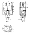
- the windproof lighter with double flames usually includes outer case 1 which is composed of bottom shell 11 , middle sleeve 12 , turnup top cover 13 and thumb piece 14.
- the lever part 15 of top cover 13 can be turned about the pivot 16 which is inserted in the middle sleeve 12.
- a spring member 17 is disposed between the end of lever part 15 and the middle sleeve 12 such that the top cover 13 is either in the closed position or in the opened position.
- a gas reservoir 2 two parts of which, i.e. the body of gas reservoir 21 and the bottom cover 22 are joined together by adhesion or welding ( ultrasonic welding ) .
- gas charging valve 23 At the bottom of gas reservoir 2 , there is mounted a gas charging valve 23 and on the gas reservoir 2 , there is also mounted a gas discharging valve 24.
- the amount of gas discharged is adjustable. The adjustment is realized by turning an adjusting rod 25.
- On the other end of the valve opening member 31 there are two extended arms 33 .
- the valve opening member 31 is supported on a fulcrum 34.
- a tee joint 41 On the nozzle 28 at the top end of valve stem 26 there is mounted a tee joint 41.
- the outlets 42 and 43 of the tee joint 41 are connected to the inlet 51 of the burner 5 and the nozzle 52 for producing visible flame through gas conduit 44 and 45 respectively.
- the burner 5 is supported by a supporter 35 , the other end of which is in contact with the metallic bottom shell 37 of the piezoelectric igniting device 36 to constitute a circuit for electricdischarge.
- the electrode 38 for discharge is led through the wall of combustion chamber 56 of the burner 5 , with its tip 39 projected into the combustion chamber 56.
- the end of the extended rod 18 of the thumb piece 14 would press down the extended arm 33 of the valve opening member 31 , the valve stem 26 is lifted through the fulcrum 34 , and the gas discharging valve 24 is opened , the gaseous fuel passes through the discharging valve 24 and is ejected from the nozzle 28.
- the piezo- electric igniting device 36 is activated to discharge from the tip 39 of discharging electrode 38, producing spark in the combustion chamber 56 , which ignites the combustible gas and the mixture of combustible gas and air.
- an adjusting device of wedge block or screw may be installed to adjust the amount of combustible gas through the gaseous fuel conduit.
- valve stems 26 and 26' of these valves both have flanges 27 and 27' at its upper portion , and at their ends are the nozzles 28 and 28' respectively.
- the former is connected with the nozzle 52 to produce visible flame through conduit 44, while the latter is connected with the inlet 51 of the burner 5 through the conduit 45.
- the valve opening member 31 has notches 32 and 32' on its one end and middle portion respectively.
- valve 24 is a pull-open valve and the valve 24' is a press-open valve , therefore the notch 32 is engaged with the lower face of flange 27 and the notch 32' is engaged with the upper face of flange 27' ; these two flanges 27 and 27' act as fulcrums one against another.
- the press- open valve 24' is opened firstly , while the pull-open valve 24 can be opened only after the valve stem 26' of the valve 24' reaches dead point thereof.
- the burner of the windproof lighter with double flames includes a fuel ejecting orifice 60 ⁇ with a very small diameter (e.g. 0 ⁇ .0 ⁇ 5mm).
- the fuel ejecting orifice 60 ⁇ may be an orifice of very small diameter punched out from a thin sheet 53 , and the thin sheet 53 is then put into a counterbore 54 and pressed tightly by a press-block 58 (Fig. 1) with a through hole in its center and the inlet 51 of burner 5 at its bottom.
- a press-block 58 Fig. 1
- On the wall of cavity 57 are located several (e.g.
- a jet pump unit coaxial with the fuel ejecting orifice 60 ⁇ .
- a section of venturi 61 On one end of the jet pump is a section of venturi 61, whose function is to stabilize the mixture of combustible gas and air entering the combustion chamber 56 by decreasing its velocity and increasing its pressure.
- a flame stabilizer 62 On the downstream region of the venturi 61 is a flame stabilizer 62 of crossbar shape. At the top center of the flame stabilizer 62 there is a combustible gas nozzle 52 used to produce visible flame.
- a baffle 63 is set between the flame stabilizer 62 and the nozzle 52. The baffle 63 and the peripheral wall of the lower portion 561 of the combustion chamber 56 form an annular passage between them.
- a slot 561' used to place the intermediate conduit 45' of L shape, whose lower end is connected with the conduit 45 in Fig. 1 and its end of horizontal segment end is connected to the nozzle 52.
- a supporting bracket 65 for igniting element is clamped between the upper portion 562 and the lower portion 561 of the combustion chamber 56.
- On the bracket is wound an igniting element 66 made from platinum wire.
- On the wall of upper portion 562 there is a boss 562' with hole used to place the discharging electrode 38, whose tip 39 is projected somewhat into the combustion chamber 56. A discharging gap is formed between the tip 39 and the igniting element 66 with its supporter 65.
- the burned mixture of combustible gas and air may also ignite the combustible gas ejected from the nozzle 52.
- the baffle 63 serves the functions of , firstly, making the uniform distribution of the mixture of combustible gas and air ejected from both sides of cross bar of the flame stabilizer 62 along the peripheral wall of combustible chamber 56; secondly, enabling the above mentioned gas mixture to flow upwards closing to the peripheral wall of combustion chamber 56 , hence the disturbance to visible flame produced by combustible gas ejected from nozzle 52 can be avoided.
- the lower portion of combustion chamber 56 corresponding to the baffle 63 and the peripheral face of the baffle 63 are all made conical to form a conical annular passage 64.
- two symmetrically arranged short slots 52' can be made on the nozzle 52.
- the object of making the peripheral face conical at the outlet 563 of combustion chamber 56 is to promote the reignition of the mixture of combustible gas and air by the igniting element 66 when the flame is blown out by the wind , further to Improve the ignition speed of the combustible gas ejected from the nozzle 52.
- the structure of the burner is distinguished from that shown in fig.3 and 'fig.4 in that the igniting element 66 and its supporter 65 is inverted.
- the tip 39 of the discharging electrode projected somewhat more into the combustion chamber 56.
- a conical boss 562 is also required for supporting the electrode 38 .
- the inverted igniting element 66 and its supporter 65 can make the visible flame produced even more stable , and the projection of the tip 39 of discharging electrode into the combustion chamber 56 is to make the position of discharging gap more adequately.
- the supporting bracket 65 includes a central ring 651 and several (e.g. four) legs 652 inclined relative to the ring plane with its one end located on the outer periphery of the ring 651 , and a segment of its another end bent into flange 653 parallel to the ring 651.
- the flange is used to be clamped in position between the upper portion 562 and the lower portion 561 of the combustion chamber .
- the end of the flange 653 can be further bent into a short vertical flange 653'.
- the supporter 65' is made of four U-shaped supports interconnected end to end together forming a cross-shaped bracket.
- the igniting elements 66' are wound around each U- shaped support.
- the arms of the U-shaped support can also be cut with small notches to prevent the igniting element from deformation.
- the igniting elements should be connected in pairs , i.e. using one platinum wire wound on two nighbering U-shaped supports.
- the cross-shaped supporting bracket and the igniting elements 66' wound on it are clamped together between the upper portion 562 and the lower portion 561 of the combustion chamber. Obviously, the igniting element and its supporter of this kind is easily made and assembled.
- FIG. 11-Fig. 13 as compared with the structures shown in Fig. 3- Fig. 10 ⁇ , the distinction lies in the cross sectional shape and their arrangement of the combustion chamber, the igniting elements and supporters in the combustion chamber.
- the cross section of the combustion chamber 56'' as shown is an oval shape.
- the combustion chamber is an integral structure and the opening at the lower portion is still a circle.
- the baffle 63'' is also made in approximately oval shape.
- the supporter 65'' has a structure of frame shape with four extended legs 651''.
- the igniting element 66'' is wound around the frame part 652'' , small notches can also be cut out on the frame part 652''.
- combustion chamber 56'' On the inside wall of combustion chamber 56'' there are four longitudinal grooves 561'' located symmetrically, used for inserting two sets of igniting element and their supporters , in which the igniting element 66'' is wound around the supporting bracket 65'' into a spiral shape of elliptical cross section.
- the longer axis of igniting element 66'' is perpendicular to the longer axis of cross section of combustion chamber 56''
- the longer axis of cross bar of the flame stabilizer 62'' is also perpendicular to the longer axis of cross section of combustion chamber 56''.
- the electrode 38 in Fig.1 is wound around the outer periphery of the counterbore 54, so that the nozzle 52 serves as a discharging electrode and the igniting element 66'' with its supporter 65'' act as the second discharging electrode.
- two symmertical short slots 52'' with its direction parallel to the longer axis of combustion chamber 56 can be cut out on the nozzle 52.
- gaseous fuel entering the burner 5 is ejected with high speed from the fuel ejecting orifice 60 ⁇ , forming a current of high speed gas stream with a shape like a straight line.
- the gas stream hits on the cross bar of the flame stabilizer 62 and is dispersed , mixed with the air which is aspirated from the air intake holes 59 on the wall of the cavity 51, then the mixture of gaseous fuel and air is elected from the two sides of cross bar of flame stabilizer 62.
- the mixture of combustible gas and air can flow upward only along the periphery of combustion chamber 56. At last, there is a current of combustible gas in the center , while on the periphery there is a ring of mixture of combustible gas and air.
- the piezoelectric igniting device 36 is activated , and the electricity is discharged from the tip 39 of the discharging electrod 38 toward the igniting element 66 and its supporter 65.
- the electric spark produced firstly ignites the mixture of combustible gas and air.
- the second spark is produced between the igniting element 66 with its supporter 65 and the gaseous fuel nozzle 52.
- the gaseous fuel ejected from the nozzle 52 is ignited by that spark and by the already burned mixture of combustible gas and air as well.
Landscapes
- Engineering & Computer Science (AREA)
- Chemical & Material Sciences (AREA)
- Combustion & Propulsion (AREA)
- Mechanical Engineering (AREA)
- General Engineering & Computer Science (AREA)
- Chemical Kinetics & Catalysis (AREA)
- Lighters Containing Fuel (AREA)
Claims (13)
- Allume-cigarettes protégé contre le vent, à double flamme, comprenant: un boîtier (1), un réservoir (2) pour stocker le gaz carburant, une valve de remplissage de gaz (23) montée sur ledit réservoir, une valve de décharge de gaz (24) à débit de gaz réglable et un élément d'ouverture de valve (31), une buse (28) de ladite valve de décharge de gaz reliée à l'entrée (51) d'un brûleur d'allumage par l'intermédiaire d'une tuyauterie de gaz carburant (44), un dispositif d'allumage piézoélectrique (36), comprenant un élément d'allumage catalytique (66), ledit dispositif d'allumage étant actionné lors de l'ouverture de ladite valve de décharge de gaz, ledit brûleur comprenant une chambre de combustion (56), une seconde tuyauterie de gaz (45), reliée à une buse d'injection de gaz carburant (52), l'ouverture de ladite buse de carburant (52) étant dirigée verticalement vers le haut, caractérisé en ce que le brûleur comprend une pompe à jet, un stabilisateur de flamme (62) et la chambre de combustion (56), ladite pompe comprenant un orifice d'éjection de carburant (60) coaxial à sa partie entrée, et une pluralité de passages d'arrivée d'air (59) sur la paroi d'un passage aval, s'étendant à partir dudit orifice d'éjection de carburant (60), ladite chambre de combustion (56) étant disposée coaxialement et en aval de ladite pompe d'injection, ledit stabilisateur de flamme formant un canal (64) avec la paroi de la partie inférieure de la chambre de combustion, ledit élément d'allumage (66) étant agencé sur la partie aval de ladite chambre de combustion et à proximité de sa paroi, ladite buse d'injection de carburant (52) étant située dans la partie centrale supérieure dudit stabilisateur de flamme pour produire une flamme visible et la zone centrale en coupe transversale de ladite chambre de combustion étant vide, de manière que le gaz combustible puisse être éjecté vers le haut sans interruption, et ledit stabilisateur de flamme (62) comprenant un moyeu central et une chicane (63) de manière à former ledit canal (64) entre la circonférence de ladite chicane et la paroi de ladite chambre de combustion (56).
- Un allume-cigarettes protégé contre le vent, à double flamme, selon la revendication 1, caractérisé en ce que deux valves de décharge de gaz sont prévues, l'une d'elles étant reliée à ladite buse pour produire une flamme visible à travers une conduite, et l'autre étant reliée à l'entrée dudit brûleur par l'intermédiaire d'une autre conduite.
- Un allume-cigarettes protégé contre le vent, à double flamme, selon la revendication 1, caractérisé en ce qu'un raccord en T est monté sur la buse de ladite valve de décharge de gaz, l'une des sorties étant reliée à l'entrée dudit brûleur par l'intermédiaire d'un tuyau, et l'autre sortie étant reliée, par l'intermédiaire d'un autre tuyau, à la buse, au centre de la partie supérieure dudit stabilisateur de flamme, ainsi qu'une ouverture dirigée verticalement vers le haut.
- Un allume-cigarettes protégé contre le vent, à double flamme, selon les revendications 1 et 3, caractérisé en ce que l'électrode de décharge dudit dispositif d'allumage piézoélectrique est disposée en saillie à travers la paroi de la chambre de combustion réalisée en matériau réfractaire et isolant électrique, tel que de la céramique, et que la pointe de ladite électrode de décharge est disposée relativement en saillie dans ladite chambre de combustion, dans une position en aval dudit élément d'allumage et son support. Le premier entrefer ou intervalle de décharge est ainsi formé entre la pointe de ladite électrode de décharge et ledit élément d'allumage et son support, et le second entrefer ou intervalle de décharge est formé entre ledit élément d'allumage et son support et ladite buse, à la partie centrale supérieure dudit stabilisateur de flamme, avec son ouverture dirigée verticalement vers le haut.
- Un allume-cigarettes protégé contre le vent, à double flamme, selon la revendication 4, caractérisé en ce que le support dudit élément d'allumage comprend une bague centrale et plusieurs pattes dirigées vers l'extérieur à partir de la périphérie de ladite bague centrale, en oblique par rapport au plan de la bague, l'autre extrémité étant repliée pour former un segment de bride parallèle au plan de la boucle. De petites entailles sont découpées dans chaque patte. Ledit élément d'allumage est enroulé autour de son support de manière à former une configuration conique ou voisine d'une pyramide à côtés multiples.
- Un allume-cigarettes protégé contre le vent, à double flamme, selon la revendication 5, caractérisé en ce que la bride formée à l'extrémité extérieure du support dudit élément d'allumage est serrée entre les parties supérieure et inférieure de ladite chambre de combustion, et la petite extrémité dudit élément d'allumage de forme conique est située dans une position en aval de ladite chambre de combustion.
- Un allume-cigarettes protégé contre le vent, à double flamme, selon la revendication 5, caractérisé en ce que la bride formée à l'extrémité extérieure du support dudit élément d'allumage est serrée entre les parties supérieure et inférieure de ladite chambre de combustion et que la grande extrémité de forme conique dudit élément d'allumage est située en position aval de ladite chambre de combustion.
- Un allume-cigarettes protégé contre le vent, à double flamme, selon la revendication 4, caractérisé en ce que le support dudit élément d'allumage est composé de quatre supports en U, reliés mutuellement bout à bout de manière à former un support cruciforme. Lesdits éléments d'allumage sont enroulés autour de chaque support en U et deux éléments d'allumage adjacents sont reliés ensemble par paires.
- Un allume-cigarettes protégé contre le vent, à double flamme, selon les revendications 1 et 3, caractérisé en ce que ladite chambre de combustion est de forme ovale en coupe transversale, la chicane est approximativement de forme ovale. Lesdits éléments d'allumage sont enroulés autour de deux châssis de support à quatre pieds déployés de forme hélicoïdale, elliptique en coupe transversale, Lesdits châssis de support sur lesquels ledit élément d'allumage est enroulé sont introduits dans les rainures ménagées symétriquement sur la paroi interne de ladite chambre de combustion ovale. Le grand axe dudit élément d'allumage est parallèle au petit axe de ladite chambre de combustion.
- Un allume-cigarettes protégé contre le vent, à double flamme, selon la revendication 1, caractérisé en ce que ledit stabilisateur est une traverse située en position aval à partir d'un Venturi.
- Un allume-cigarettes protégé contre le vent, à double flamme, selon la revendication 1, caractérisé en ce que la partie inférieure de ladite chambre de combustion correspondant à la chicane et la face périphérique de ladite chicane sont toutes deux de forme conique de manière à constituer un passage annulaire conique.
- Un allume-cigarettes protégé contre le vent, à double flamme, selon la revendication 1, caractérisé en ce que deux courtes fentes de faible longueur sont ménagées longitudinalement à la sortie de ladite buse de gaz carburant.
- Un allume-cigarettes protégé contre le vent, à double flamme, selon la revendication 1, caractérisé en ce que la face périphérique de la paroi interne, à la sortie de ladite chambre de combustion, est de forme conique.
Applications Claiming Priority (4)
| Application Number | Priority Date | Filing Date | Title |
|---|---|---|---|
| CN89214319 | 1989-07-26 | ||
| CN 89214319 CN2064459U (zh) | 1989-07-26 | 1989-07-26 | 双火苗防风打火机 |
| CN 90204107 CN2067359U (zh) | 1990-04-14 | 1990-04-14 | 防风打火机 |
| CN90204107 | 1990-04-14 |
Publications (2)
| Publication Number | Publication Date |
|---|---|
| EP0410313A1 EP0410313A1 (fr) | 1991-01-30 |
| EP0410313B1 true EP0410313B1 (fr) | 1994-06-15 |
Family
ID=25742600
Family Applications (1)
| Application Number | Title | Priority Date | Filing Date |
|---|---|---|---|
| EP90113898A Expired - Lifetime EP0410313B1 (fr) | 1989-07-26 | 1990-07-20 | Allume-cigarettes imperméable au vent et à flammes doubles |
Country Status (4)
| Country | Link |
|---|---|
| US (1) | US5055034A (fr) |
| EP (1) | EP0410313B1 (fr) |
| JP (1) | JP2633070B2 (fr) |
| DE (1) | DE69009884T2 (fr) |
Families Citing this family (38)
| Publication number | Priority date | Publication date | Assignee | Title |
|---|---|---|---|---|
| US5215458A (en) | 1988-03-04 | 1993-06-01 | Bic Corporation | Child-resistant lighter with spring-biased, rotatable safety release |
| US5584682A (en) | 1988-09-02 | 1996-12-17 | Bic Corporation | Selectively actuatable lighter with anti-defeat latch |
| US5456598A (en) | 1988-09-02 | 1995-10-10 | Bic Corporation | Selectively actuatable lighter |
| US5002482B1 (en) | 1988-09-02 | 2000-02-29 | Bic Corp | Selectively actuatable lighter |
| DE69102875T2 (de) * | 1990-06-01 | 1995-02-02 | Lowenthal | Feuerzeug mit flamme. |
| US5726421A (en) * | 1991-03-11 | 1998-03-10 | Philip Morris Incorporated | Protective and cigarette ejection system for an electrical smoking system |
| GB9113215D0 (en) * | 1991-06-14 | 1991-08-07 | Lowenthal Hans | Flame lighter |
| GB2260602B (en) * | 1991-10-14 | 1995-05-17 | Kohga Press Kogyo Co Ltd | Gas lighter having two burners |
| JPH0622754U (ja) * | 1991-10-14 | 1994-03-25 | 甲賀プレス工業株式会社 | ガスライター |
| JPH0596752U (ja) * | 1992-02-14 | 1993-12-27 | 甲賀プレス工業株式会社 | ガスライター |
| JPH086923B2 (ja) * | 1992-12-04 | 1996-01-29 | 株式会社サロメ | ガス燃焼装置 |
| EP0578945A3 (fr) * | 1992-07-17 | 1996-04-03 | Takaaki Segawa | Briquet |
| JPH086924B2 (ja) * | 1993-01-05 | 1996-01-29 | 株式会社サロメ | ライタ− |
| JPH0744011U (ja) * | 1992-07-24 | 1995-10-24 | キム ジョン イル | ライターが取りつけられた筆記具 |
| JPH06109247A (ja) * | 1992-09-22 | 1994-04-19 | Koei Kogyo Kk | 2態様の燃焼形式を備えた喫煙用ライター |
| JPH06123427A (ja) * | 1992-10-09 | 1994-05-06 | Koei Kogyo Kk | 喫煙用ライターのバーナー装置 |
| JP2578768Y2 (ja) * | 1992-12-28 | 1998-08-13 | 成秋 鈴木 | ガスライター |
| JPH06300257A (ja) * | 1993-04-15 | 1994-10-28 | Koei Kogyo Kk | 喫煙用ライターのバーナー装置 |
| US5457359A (en) * | 1993-08-06 | 1995-10-10 | Olin Corporation | Control for electroluminescent loads |
| JPH0732357U (ja) * | 1993-10-27 | 1995-06-16 | 株式会社宮本製作所 | 内燃式ライター |
| USD420762S (en) * | 1997-09-15 | 2000-02-15 | Kevin Harrington | Tobacco tool |
| US6527542B1 (en) * | 2000-10-30 | 2003-03-04 | Peter Chen | Child-proof safety device for eclipse lighter |
| US6461146B1 (en) * | 2000-11-17 | 2002-10-08 | Zreative Product Inc. | Adjustable jet flame utility lighter |
| JP2004528524A (ja) * | 2001-06-07 | 2004-09-16 | ラン ウォン,チー | 多数のトーチ状炎のライター |
| AU2002231946A1 (en) * | 2002-02-08 | 2003-09-02 | Tak Chi Sher | Sealing method and article |
| US20040096793A1 (en) * | 2002-11-18 | 2004-05-20 | Wong Chi Lam | Windproof lighter with flint igniter |
| US20040202978A1 (en) * | 2003-04-11 | 2004-10-14 | Wong Ming King | Lighter nozzle system for producing stylish torch |
| US6884063B2 (en) * | 2003-05-23 | 2005-04-26 | Chi Lam Wong | Multiple-flame lighter |
| US6773258B1 (en) * | 2003-08-02 | 2004-08-10 | Chi Lam Wong | Windproof lighter |
| US7214055B2 (en) * | 2003-11-10 | 2007-05-08 | Zippo Manufacturing Company | Colinear burner |
| US7654821B2 (en) * | 2004-02-17 | 2010-02-02 | Zippo Manufacturing Company | Flint ignited premixed lighter |
| CN2699146Y (zh) * | 2004-04-17 | 2005-05-11 | 伍爱明 | 一种双火苗打火机 |
| US7011515B1 (en) * | 2004-10-18 | 2006-03-14 | Huang-Hsi Hsu | Gas lighter having device for preventing flame from being extinguished by wind |
| CN1304788C (zh) * | 2005-04-26 | 2007-03-14 | 潘浩才 | 防风打火机 |
| US10088158B2 (en) | 2014-07-15 | 2018-10-02 | Daniel Rahbar | Retractable directional flame nozzle for lighter |
| AU2017290132B2 (en) | 2016-06-29 | 2019-10-31 | Worthington Industries, Inc. | Torch having a rotatable safety cap |
| FR3068767B1 (fr) * | 2017-07-07 | 2019-07-19 | St Dupont | Briquet apte a emettre deux flammes differentes en alternance |
| WO2022060912A1 (fr) | 2020-09-15 | 2022-03-24 | Dillon Reilly M | Briquet |
Family Cites Families (14)
| Publication number | Priority date | Publication date | Assignee | Title |
|---|---|---|---|---|
| FR1564840A (fr) * | 1967-03-11 | 1969-04-25 | ||
| JPS516305Y1 (fr) * | 1968-09-11 | 1976-02-20 | ||
| US3844707A (en) * | 1971-05-11 | 1974-10-29 | Wingaersheek Turbine Co Inc | Low cost, wind proof cigarette lighter burner |
| JPS5040072B2 (fr) * | 1971-10-20 | 1975-12-22 | ||
| GB1452264A (en) * | 1972-08-29 | 1976-10-13 | Barrington R R | Illuminating head for a gas burning torch |
| US3915623A (en) * | 1973-08-20 | 1975-10-28 | Wingaersheek | Wind-proof cigarette lighter burner |
| JPS50102666U (fr) * | 1974-01-21 | 1975-08-25 | ||
| JPS56103757U (fr) * | 1979-12-29 | 1981-08-13 | ||
| JPS60188023A (ja) * | 1984-03-09 | 1985-09-25 | 松下電器産業株式会社 | ガス触媒ヒ−タ |
| JPS63104848A (ja) * | 1986-10-21 | 1988-05-10 | Matsushita Electric Ind Co Ltd | 電極ヘツド駆動回路 |
| CH672017A5 (fr) * | 1987-07-10 | 1989-10-13 | Nationale Sa | |
| JPS6481456A (en) * | 1987-09-22 | 1989-03-27 | Nec Corp | Facsimile sender confirming system |
| US4941818A (en) * | 1987-11-21 | 1990-07-17 | Tdk Corporation | Cigarette lighter |
| FR2627848B1 (fr) * | 1988-02-25 | 1992-10-30 | Segawa Takaaki | Briquet a gaz protege contre le vent |
-
1990
- 1990-07-20 DE DE69009884T patent/DE69009884T2/de not_active Expired - Fee Related
- 1990-07-20 EP EP90113898A patent/EP0410313B1/fr not_active Expired - Lifetime
- 1990-07-25 US US07/557,341 patent/US5055034A/en not_active Expired - Lifetime
- 1990-07-26 JP JP2198942A patent/JP2633070B2/ja not_active Expired - Fee Related
Also Published As
| Publication number | Publication date |
|---|---|
| HK1003231A1 (en) | 1998-10-16 |
| JP2633070B2 (ja) | 1997-07-23 |
| EP0410313A1 (fr) | 1991-01-30 |
| JPH03186114A (ja) | 1991-08-14 |
| DE69009884T2 (de) | 1994-09-22 |
| DE69009884D1 (de) | 1994-07-21 |
| US5055034A (en) | 1991-10-08 |
Similar Documents
| Publication | Publication Date | Title |
|---|---|---|
| EP0410313B1 (fr) | Allume-cigarettes imperméable au vent et à flammes doubles | |
| US5246365A (en) | Reignition device for a gas burner | |
| US5584681A (en) | Gas lighter | |
| US3843311A (en) | Lantern with igniter | |
| HK1003231B (en) | Windproof cigarette lighter with double flames | |
| US3879163A (en) | Lighter assembly | |
| US6213760B1 (en) | Burner for portable gas cooking stove | |
| US4019851A (en) | High energy arc ignitor for burner | |
| JPH0264320A (ja) | 可燃材料点火装置 | |
| WO1998009114A1 (fr) | Dispositif d'allumage pour rechaud portatif | |
| JP2575079B2 (ja) | 内燃式ガスライター | |
| JPH10238773A (ja) | シガレットライターのバーナーノズル | |
| JP2996560B2 (ja) | ランタン用バーナー | |
| EP0382893A1 (fr) | Détecteur pour brûleur | |
| JPH04214107A (ja) | ガスバーナ | |
| JP2602585Y2 (ja) | ガスライター | |
| JP3042319U (ja) | シガー用ガスライター | |
| KR950005450Y1 (ko) | 불꽃형 버너형 겸용 가스라이터 | |
| JPH07217878A (ja) | 点火器における燃焼装置 | |
| JPH0634134A (ja) | ライタ−のガス燃焼装置 | |
| JPH06123427A (ja) | 喫煙用ライターのバーナー装置 | |
| EP1405010A1 (fr) | Briquet a flammes multiples en forme de torche | |
| JPH086921B2 (ja) | ライタ−のガス燃焼装置 | |
| CN2082359U (zh) | 双火苗防风打火机 | |
| GB2301424A (en) | Gas lighter |
Legal Events
| Date | Code | Title | Description |
|---|---|---|---|
| PUAI | Public reference made under article 153(3) epc to a published international application that has entered the european phase |
Free format text: ORIGINAL CODE: 0009012 |
|
| AK | Designated contracting states |
Kind code of ref document: A1 Designated state(s): DE FR GB |
|
| 17P | Request for examination filed |
Effective date: 19901208 |
|
| 17Q | First examination report despatched |
Effective date: 19920205 |
|
| GRAA | (expected) grant |
Free format text: ORIGINAL CODE: 0009210 |
|
| AK | Designated contracting states |
Kind code of ref document: B1 Designated state(s): DE FR GB |
|
| REF | Corresponds to: |
Ref document number: 69009884 Country of ref document: DE Date of ref document: 19940721 |
|
| ET | Fr: translation filed | ||
| PLBE | No opposition filed within time limit |
Free format text: ORIGINAL CODE: 0009261 |
|
| STAA | Information on the status of an ep patent application or granted ep patent |
Free format text: STATUS: NO OPPOSITION FILED WITHIN TIME LIMIT |
|
| 26N | No opposition filed | ||
| PGFP | Annual fee paid to national office [announced via postgrant information from national office to epo] |
Ref country code: GB Payment date: 19970704 Year of fee payment: 8 |
|
| PGFP | Annual fee paid to national office [announced via postgrant information from national office to epo] |
Ref country code: FR Payment date: 19970729 Year of fee payment: 8 |
|
| PGFP | Annual fee paid to national office [announced via postgrant information from national office to epo] |
Ref country code: DE Payment date: 19970927 Year of fee payment: 8 |
|
| PG25 | Lapsed in a contracting state [announced via postgrant information from national office to epo] |
Ref country code: GB Free format text: LAPSE BECAUSE OF NON-PAYMENT OF DUE FEES Effective date: 19980720 |
|
| GBPC | Gb: european patent ceased through non-payment of renewal fee |
Effective date: 19980720 |
|
| PG25 | Lapsed in a contracting state [announced via postgrant information from national office to epo] |
Ref country code: FR Free format text: LAPSE BECAUSE OF NON-PAYMENT OF DUE FEES Effective date: 19990331 |
|
| PG25 | Lapsed in a contracting state [announced via postgrant information from national office to epo] |
Ref country code: DE Free format text: LAPSE BECAUSE OF NON-PAYMENT OF DUE FEES Effective date: 19990501 |
|
| REG | Reference to a national code |
Ref country code: FR Ref legal event code: ST |