EP0410317A2 - Système non-envahissant et méthode pour surveiller des vannes - Google Patents
Système non-envahissant et méthode pour surveiller des vannes Download PDFInfo
- Publication number
- EP0410317A2 EP0410317A2 EP90113926A EP90113926A EP0410317A2 EP 0410317 A2 EP0410317 A2 EP 0410317A2 EP 90113926 A EP90113926 A EP 90113926A EP 90113926 A EP90113926 A EP 90113926A EP 0410317 A2 EP0410317 A2 EP 0410317A2
- Authority
- EP
- European Patent Office
- Prior art keywords
- valve
- data
- movable element
- accelerometer
- signals
- Prior art date
- Legal status (The legal status is an assumption and is not a legal conclusion. Google has not performed a legal analysis and makes no representation as to the accuracy of the status listed.)
- Granted
Links
- 238000000034 method Methods 0.000 title claims abstract description 53
- 238000007689 inspection Methods 0.000 title claims abstract description 52
- 230000005355 Hall effect Effects 0.000 claims description 22
- 238000004458 analytical method Methods 0.000 claims description 20
- 238000012545 processing Methods 0.000 claims description 17
- 230000009977 dual effect Effects 0.000 claims description 13
- 239000012530 fluid Substances 0.000 claims description 10
- 239000013078 crystal Substances 0.000 claims description 6
- 230000004044 response Effects 0.000 description 11
- 230000003116 impacting effect Effects 0.000 description 7
- 238000010586 diagram Methods 0.000 description 6
- 238000001514 detection method Methods 0.000 description 4
- 238000012423 maintenance Methods 0.000 description 3
- 239000000523 sample Substances 0.000 description 3
- 239000004593 Epoxy Substances 0.000 description 2
- 230000003321 amplification Effects 0.000 description 2
- 238000004364 calculation method Methods 0.000 description 2
- 238000013480 data collection Methods 0.000 description 2
- 238000001914 filtration Methods 0.000 description 2
- 230000006870 function Effects 0.000 description 2
- 238000012986 modification Methods 0.000 description 2
- 230000004048 modification Effects 0.000 description 2
- 238000003199 nucleic acid amplification method Methods 0.000 description 2
- 238000012552 review Methods 0.000 description 2
- 238000012360 testing method Methods 0.000 description 2
- 238000012546 transfer Methods 0.000 description 2
- 230000003245 working effect Effects 0.000 description 2
- 230000002159 abnormal effect Effects 0.000 description 1
- 238000004422 calculation algorithm Methods 0.000 description 1
- 230000015556 catabolic process Effects 0.000 description 1
- 239000000919 ceramic Substances 0.000 description 1
- 238000006243 chemical reaction Methods 0.000 description 1
- 238000004590 computer program Methods 0.000 description 1
- 238000007405 data analysis Methods 0.000 description 1
- 238000013500 data storage Methods 0.000 description 1
- 230000003247 decreasing effect Effects 0.000 description 1
- 238000006731 degradation reaction Methods 0.000 description 1
- 238000013461 design Methods 0.000 description 1
- 238000007435 diagnostic evaluation Methods 0.000 description 1
- 125000003700 epoxy group Chemical group 0.000 description 1
- 229910052738 indium Inorganic materials 0.000 description 1
- APFVFJFRJDLVQX-UHFFFAOYSA-N indium atom Chemical compound [In] APFVFJFRJDLVQX-UHFFFAOYSA-N 0.000 description 1
- 238000009434 installation Methods 0.000 description 1
- 238000011835 investigation Methods 0.000 description 1
- 239000003550 marker Substances 0.000 description 1
- 230000007246 mechanism Effects 0.000 description 1
- 229910052751 metal Inorganic materials 0.000 description 1
- 239000002184 metal Substances 0.000 description 1
- 229920000647 polyepoxide Polymers 0.000 description 1
- 239000002243 precursor Substances 0.000 description 1
- 230000008569 process Effects 0.000 description 1
- 238000011160 research Methods 0.000 description 1
- 230000000284 resting effect Effects 0.000 description 1
- 230000001052 transient effect Effects 0.000 description 1
- 238000011179 visual inspection Methods 0.000 description 1
- 238000003466 welding Methods 0.000 description 1
Images


Classifications
-
- F—MECHANICAL ENGINEERING; LIGHTING; HEATING; WEAPONS; BLASTING
- F16—ENGINEERING ELEMENTS AND UNITS; GENERAL MEASURES FOR PRODUCING AND MAINTAINING EFFECTIVE FUNCTIONING OF MACHINES OR INSTALLATIONS; THERMAL INSULATION IN GENERAL
- F16K—VALVES; TAPS; COCKS; ACTUATING-FLOATS; DEVICES FOR VENTING OR AERATING
- F16K37/00—Special means in or on valves or other cut-off apparatus for indicating or recording operation thereof, or for enabling an alarm to be given
- F16K37/0025—Electrical or magnetic means
- F16K37/0041—Electrical or magnetic means for measuring valve parameters
-
- F—MECHANICAL ENGINEERING; LIGHTING; HEATING; WEAPONS; BLASTING
- F16—ENGINEERING ELEMENTS AND UNITS; GENERAL MEASURES FOR PRODUCING AND MAINTAINING EFFECTIVE FUNCTIONING OF MACHINES OR INSTALLATIONS; THERMAL INSULATION IN GENERAL
- F16K—VALVES; TAPS; COCKS; ACTUATING-FLOATS; DEVICES FOR VENTING OR AERATING
- F16K37/00—Special means in or on valves or other cut-off apparatus for indicating or recording operation thereof, or for enabling an alarm to be given
- F16K37/0075—For recording or indicating the functioning of a valve in combination with test equipment
- F16K37/0083—For recording or indicating the functioning of a valve in combination with test equipment by measuring valve parameters
-
- Y—GENERAL TAGGING OF NEW TECHNOLOGICAL DEVELOPMENTS; GENERAL TAGGING OF CROSS-SECTIONAL TECHNOLOGIES SPANNING OVER SEVERAL SECTIONS OF THE IPC; TECHNICAL SUBJECTS COVERED BY FORMER USPC CROSS-REFERENCE ART COLLECTIONS [XRACs] AND DIGESTS
- Y10—TECHNICAL SUBJECTS COVERED BY FORMER USPC
- Y10S—TECHNICAL SUBJECTS COVERED BY FORMER USPC CROSS-REFERENCE ART COLLECTIONS [XRACs] AND DIGESTS
- Y10S73/00—Measuring and testing
- Y10S73/03—Hall effect
-
- Y—GENERAL TAGGING OF NEW TECHNOLOGICAL DEVELOPMENTS; GENERAL TAGGING OF CROSS-SECTIONAL TECHNOLOGIES SPANNING OVER SEVERAL SECTIONS OF THE IPC; TECHNICAL SUBJECTS COVERED BY FORMER USPC CROSS-REFERENCE ART COLLECTIONS [XRACs] AND DIGESTS
- Y10—TECHNICAL SUBJECTS COVERED BY FORMER USPC
- Y10T—TECHNICAL SUBJECTS COVERED BY FORMER US CLASSIFICATION
- Y10T137/00—Fluid handling
- Y10T137/8158—With indicator, register, recorder, alarm or inspection means
- Y10T137/8225—Position or extent of motion indicator
Definitions
- This invention relates to valves and more particularly to a non-invasive system and method for the inspection of valves.
- a check-valve includes a housing and a movable element mounted in the housing for movement between an open position and a closed position and intermediate positions between the open and closed positions.
- the check-valve operates by allowing flow in one direction when the movable element is in the open position while preventing flow in the other when the movable element is in the closed position.
- the check valve has no external moving parts and, therefore, the position of the movable element and its integrity cannot be evaluated with normal visual inspection methods without valve disassembly.
- inspection of check valves is generally accomplished by the disassembly of the valve and visually inspecting the internals.
- non-invasive inspection techniques consisting of ultrasonic, acoustic or, to a limited extent, magnetic techniques.
- Acoustic techniques involve the detection of structural-borne noise, i e. acoustic energy or vibrations, emanating from the internal workings of the valve.
- the acoustic technigue generally employs a piezoelectric crystal sensor, such as an accelerometer, mounted on the valve housing. All structural-borne acoustic energy waves or vibrations are detected by the acoustic sensor and converted by it to electric analog voltage signals or data representative of acoustic energy. The data is recorded and then analyzed in an attempt to diagnose which internal valve condition the data is indicating.
- the indications of various conditions and/or "problems" within the valve can be detected as vibrations by the acoustic sensor, the interpretation of the data as to which problem the acoustic energy or vibrations is indicating is difficult. For example, it is difficult at times, to differentiate betweenvibrations caused by impacts between worn parts and impacts which are expected in normal operation of the valve, i.e., impacts which occur upon the opening and closing of the valve. Also vibrations created by impacts caused by worn parts as the movable element fluctuates between open and closed positions can te misinterpreted as vibrations created by impacts caused by the movable member striking the valve housing or a valve stop in its fully opened position.
- Magnetic techniques for the inspection of valves currently relate to systems which provide information regarding the position of the movable element of the valve.
- the magnetic technique involves the use of a permanent magnet mounted on the movable element to provide a varying magnetic field as the position of the movable element changes.
- a magnet field sensor is used to measure the magnetic field strength from a point outside the valve. As magnetic field strength changes, the sensor will indicate the position of the movable element. Knowing the position of the movable element permits limited diagnostic evaluation of check valves. For example, a fluctuating movable element will be evident using the magnetic technique. Proper seating of the movable element upon closure, however, would not be evident using magnetic techniques although the position of the movable element would indicate closed. Also, and more importantly, worn internal parts would not be evident using magnetic techniques.
- the invention provides a non-invasive inspection system for a valve of the type including a housing and a movable element mounted in the housing for movement between an open position and closed position and intermediate positions between the open and closed positions.
- First means are provided for both detecting acoustic energy in the valve during an inspection interval and generating data representative of the detected acoustic energy.
- Second means are provided for both detecting signals indicative of the position of the movable element during an inspection interval and generating data representative of the detected signals.
- Third means are provided which are coupled to the first and second means for simultaneously receiving the data generated by the first and second means.
- a non-invasive method of inspecting a valve of the type having a housing and an internal element mounted in the housing for movement between open and closed positions and intermediate positions between the open and closed positions comprises the steps of: detecting acoustic energy in the valve during an inspection interval and generating data representative of the detected acoustic energy; detecting signals indicative of the position of the movable element during an inspection interval and generating data representative of the detected signals; recording the data generated for subsequent analysis and/or processing the data generated to place the data generated in a form for analysis whereby to detect various conditions within the valve.
- Still another aspect of the invention is the provision of a dual sensor.
- the dual sensor comprises in combination: a container; first means disposed in the container for both detecting acoustic energy and generating data representative of the detected acoustic energy; and, second means disposed in the container for both detecting magnetic field strength signals and generating data representative of the detected signals.
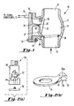
- swing check valve is the most common check valve in use and the system and method in accordance with the invention will be described in association with the swing check valve. It is to be understood, however, that the system and method of the invention applies to all check valves including the so-called “tilting disk” check valve and the so-called “lift check” valve.
- the swing check valve 10 comprises a valve body or housing 11 which has a chamber 14 therein and includes an inlet opening 16 and an outlet 15 which respectively communicate with opposite ends of the chamber 14.
- a movable element or disk 20 is hingedly supported on the housing 12 by hinge arm 22 and hinge pin 24.
- the disk 20 is disposed in the path of fluid flow from the inlet opening 16 to the outlet opening 18 and is mounted for pivotal movement about the hinge pin 24, generally toward the outlet opening 18, in response to fluid flow through the housing 11.
- the disk 20 is mounted on the hinge arm 22 by washer 26 and nut 28.
- Access to the interior of the valve is provided by means of removable valve bonnet 30 which is secured to valve housing Il by bolts and nuts 32 and 34, respectively. Only one of such bolts and nuts are shown in Figure 1. when the valve is closed, disk 20 is in engagement with disk seat 36 and when it is in its fully opened position, disk 20 contacts and rests against disk stop 38.
- disk 20 is movable between an open position with disk 20 resting against disk stop 38 and a closed position with disk 20 in engagement with disk seat 36 and, intermediate positions between the open and closed positions depending upon the level of fluid flow from the inlet opening 16 to the outlet opening 18.
- the disk 20 closes tightly against the disk seat 36 preventing back leakage.
- the valve disk assembly i.e., the hinge arm 22, disk 20, washer 26 and nut 28, will contact the disk stop 38 during the opening and should come to rest on the stop 38.
- a valve in "poor” condition i.e., with internal damage or in an inadequate design application, may not close tightly. That is, disk 20 may not close tightly against the disk seat 36 and back leakage may occur.
- wear on the hinge pin 24 may cause the hinge pin 24 to rattle; wear on the hinge arm 22 may cause the arm 22 to rattle; and/or, wear on the disk nut 28 may cause the disk 20 to wobble.
- insufficient flow of fluid through the valve 10 causes the disk 20 to fluctuate to positions intermediate fully open and closed positions continuously and results in excessive wear on the hinge pin 24. If such fluctuations include the valve disk assembly striking the valve stop 38, excessive wear will occur on the disk nut 28 and hinge arm assembly, i.e., the hinge arm 22, the hinge pin 24 and their respective associated structures.
- An effective inspection technique for check valves should be able to detect the following conditions: disk position; wear of internal parts; loose or missing internal parts; and, disk/disk seat leakage.
- an effective inspection technique should be able to determine: stroke time, i.e., the time for the disk to move from the closed position to the open position; whether or not the disk is in the fully opened, fully closed or intermediate position; flutter of the disk including the magnitude and frequency of the flutter; and, any contact with the disk seats/stops.
- an effective inspection technique should be able to determine: hinge pin/bushing wear; seat/disk facing surfaces wear; and, disk to hinge arm connection wear.
- an effective inspection technique should be able to determine: the presence of leakage; and, the rate of such leakage.
- Worn internal parts can be detected by an acoustic technique because worn internal parts create abnormal clearances allowing relative motion between those parts resulting in transient impact acoustic energy waves being input to the valve structure. These relatively low energy impacts are detected by the acoustic sensor as the disk assembly moves. Therefore, worn hinge pins or hinge arms, and loose, wobbling disks can be detected by acoustic inspection techniques.
- a fluctuating disk that does not contact the disk stop or disk seat inputs no energy into the valve structure and, therefore, is not detectable by the use of an acoustic inspection technique.
- energy waves are impacted into the valve structure and can be detected by an acoustic inspection technique.
- the continued impacting of the disk to disk stop is discernible as discrete impact signatures with an acoustic inspection technique.
- the valve disk closing against the disk seat is also detectable as the disk impacts the disk seat. Normal closure is seen as a single discrete event while valves with worn parts and excessive clearance provide signatures that indicate multiple impacts as the seat wobbles into a steady state condition.
- acoustic inspection techniques are coupled with magnetic inspection techniques in a novel manner to form a non-invasive inspection system and method that clearly diagnoses deteriorated conditions within the check valve.
- a sensor which preferably, as shown in Figure 2, takes the form of a dual sensor comprised of a first means or accelerometer 52 and a second means or Hall effect generator 54 disposed in a single container 56.
- the accelerometer 52 and Hall effect generator 54 may be separate elements and be positioned in spaced apart relationship on the valve structure.
- the dual sensor 50 is attached to the valve bonnet 30 with mounting shoe 58 which is threadably received in the bottom of the container 56 of the dual sensor 50.
- the mounting shoe 58 may be attached to the bonnet 30 by bonding as, for example, by a suitable epoxy.
- a permanent magnet 60 mounted on the disk 20 for movement therewith with the North/South axis of the magnet 60 being disposed (North to South) perpendicular to the disk 20.
- a magnet with a strong magnetic field in terms of magnetic moment is preferred.
- the magnet field strength of the magnet 60 measured at either pole should be greater than 2 kilogauss.
- the magnet 60 may be mounted on the disk 20 by, for example, suitable epoxies, metal putties or welding.
- the magnet 60 may be located in an opening 62 provided in the washer 26.
- the magnet 60 may be located anywhere on the hinge arm/disk assembly for movement therewith.
- the placement of the permanent magnet 60 on the disk 20 or hinge arm 22 will provide a varying magnetic field as the position of the disk 20 changes.
- the magnetic field strength (in Gauss) as measured from a stationary point outside the valve is proportional to the position of the disk 20.
- the accelerometer 52 may, for example, comprise a piezoelectric crystal accelerometer and functions to both detect acoustic energy or vibrations in the valve during an inspection interval and generate data in the form of analog voltage signals representative of the detected acoustic energy.
- the Hall effect generator 54 may, for example, comprise a ceramic crystal such as indium arsinide, which has a transfer function of MV/Gauss.
- the Hall effect generator 54 generates data in the form of analog voltage signals representative of the detected signals, i.e., the changing magnetic field strength as the disk 20 and magnet 60 are in motion.
- the actual millivolt reading obtained from the sensor 54/electronic system (to be described below) once calibrated would indicate the position of the disk 20.
- the system comprises the dual sensor 50 which is coupled via leads 70 and 72 to third means or receiving means shown generally at 74. Essentially, the receiving means are shown to the right of the dashed vertical line 73 in Figure 3.
- the leads 70 and 72 are coupled to the input of a signal conditioner 75.
- Signal conditioner 75 comprises gauss meter circuitry which converts the Hall effect generator output to an electrical voltage through amplification and filtering, and charge amplifier circuitry which converts the accelerometer output to an electrical voltage through charge to voltage conversion, amplification and filtering.
- the signal conditioner 75 may be connected directly to a recording means or tape recorder 76 or to an analog to digital converter 78. when the system is used in the field, the signal conditioner 75 and recorder 76 may be brought to the location of the check-valve where the sensor 50 would be attached to the valve and the output signals from the sensor 50 would be recorded for subsequent analysis.
- the recorder 76 preferably includes an acoustic channel having a frequency response of 500 Hz to 10 kHz and a magnetic channel having a frequency response of 0 to 10 Hz.
- the data from the dual sensor 50 could be input directly to the analog to digital converter 78 without first recording the data from the sensor 50.
- the data generated by the sensor 50 is coupled to the analog to digital converter 78 which converts the analog voltage output signals generated by sensor 50 to digital voltage signals suitable for input to digital signal processing means or computer 80 which includes a memory 82 for storing data.
- the computer 20 is coupled to a display device 84 which provides a display 86 of data generated by the sensor 50 in a form suitable for analysis.
- the computer 20 is programmed to scan through the data input to it and locate significant data according to a predetermined algorithm. Most preferably the computer would locate data corresponding to impacts resulting from fluid flow through the valve or movement of the movable element or disk 20 and corresponding to the position of the disk 20 at the time of the internal impacts.
- FIG 11 shows a block diagram of the structure of the program (software system) used for check valve investigations.
- the Main Menu 200 is the overall control mechanism for utilizing the software routines.
- the Utilities 202 routine is used for maintenance on the computer system. Within the Utilities 202 routine would be system configuration, backup, file transfer, and DOS commands.
- the Display 204 routine contains a series of software modules used to present data on the screen 86. These modules include a preview of the data prior to data storage, data scrolling allowing scanning of data over relatively long periods of time, zooming capabilities about a cursor, and a Fast Fourier Transform (FFT)
- the Data collection 206 routines receives data from the Analog to Digital converter 78 and enters it into a file format.
- FFT Fast Fourier Transform
- the Data Base 208 routines contain all valve data taken from different plants, i.e., remote valve locations, along with information from the nameplate and tags on the valve.
- the Data Base 205 allows data comparisons between different tests on the same valve.
- the Data Analysis 210 routines contain the methods and calculations required to analyze the data to determine the condition of the valve. These calculations include time at cursors C1 and C2, acoustic and magnetic values at cursors, RMS level between cursors, Peak level between cursors, and FFT between cursors.
- the Analysis 210 routines also include standard reports that can be output to a printer (not shown)
- Figure 12 is a flow diagram used to analyze the data collected from a check valve.
- the screen is divided into two parts 300, the real time part showing the magnetic and acoustic traces and an envelop part 11.
- the ten second data sample is enveloped to allow the entire ten seconds' profile 214 to be presented within the envelop section 212 of the display.
- the first 1,000 samples or 1/200th of the 10 second data sample is presented 302.
- the real time acoustic and magnetic traces are displayed (See Figure 3)
- the analyst can scan all ten seconds of data by computer command 302. where in the ten seconds of data the 1,000 samples on the real time display is located, is shown by a marker 216 under the envelop trace (See Figure 3). This enables the analyst to quickly focus on pertinent data.
- Cursor operation 304 is the tool the analyst uses to examine the data and determine the condition of the check valve. With multiple cursors c1 and C2, the following can be accomplished. . Time between impacts . Acoustic RMS level for leak detection . Peak value between cursors . Magnetic and Acoustic values at cursor . FFT of Acoustic signal between cursor . Correlate Acoustic Impacts with Magnetic trace
- a report 306 can be generated to provide a hard copy record.
- the output data of the Hall effect generator 54 indicates the position of the disk 20 coincident with the detection of impacts within the valve or acoustic signatures, i e., output data of the accelerometer 52, indicating a valve condition such as would result from fluid flow through the valve or movement of the disk 20.
- the knowledge of the position of the disk 20 at the time of the detection of an acoustic event provides the necessary discernment required to analyze the diagnostic meaning of the acoustic events, i e. impacts or vibrations within the valve structure.
- the receiving means 74 may comprise the recorder 76 for recording the data generated by the dual sensor 50 or the data processing means which comprises the analog to digital converter 78, the digital processing means or computer 80 and the display means 84.
- the data processing means processes the data generated by the first means or accelerometer 52 and second means or Hall effect generator 54 to place the data generated by the accelerometer 52 and Hall effect generator 54 in a form for analysis.
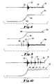
- FIGS. 4-10 are diagrammatic, acoustic and magnetic tracings as might appear on the display 86.
- Each of the traces comprise or represent approximately five milliseconds from ten seconds of recorded and processed data from the output of the accelerometer 52 and/or Hall effect generator 54.
- the computer 20 has scanned the data and selected this data for display in accordance with its program because, for example, the level of the signals as at 80-96 in the trace 79 of Figure 4 is above a predetermined level.
- the signals at 80-96 represent multiple impacts occurring within the valve. Diagnosing this acoustic signature would indicate several possible conclusions.
- Figure 4 could be indicating disk 20 to disk stop 38 impacting or disk 20 fluttering with hinge pin 24 wear or looseness or disk 28 to disk seat 36 impacting or any combination of these.
- Figure 5 is an acoustic trace with no apparent impacting. Diagnosing the trace 98 of Figure 5 could lead to two conclusions. Either the disk 28 is fluttering with no impacting or the valve internal parts are not moving. Thus, reviewing the acoustic-traces of Figures 4 and 5 alone will not provide complete diagnostics of the internal workings of the valve.
- FIG. 6 shows the response of both sensors 52 and 54 to a check valve closure.
- flow noise is seen to decrease, as at 102, followed by an impact signature, as at 104, of the disk 20 making contact with the seat 36.
- This analysis is confirmed by the magnetic trace 106.
- the magnetic signature of the valve closing shows the magnetic field strength decreasing, as at 108, to the seat or closed position, as at 110.
- Figure 7 shows the response of both sensors 52 and 54 to a check valve closing with several bounces of the disk 20 and improper valve seating, i.e., closing.
- the acoustic signature 112 shows flow noise, as at 114, up to the point where the disk 20 impacts the seat 36 three times, as at 116, 118, 120, followed by substantial leak flow noise, as at 122, indicating either a degraded disk 20 or an improperly seated disk 20.
- the magnetic trace 124 shows the disk closing, as at 126, with a bounce signature present, at as 128 and 130.
- Figure 8 shows the response of both sensors 52 and 54 for a check valve opening.
- the acoustic signature 132 begins to show flow noise, as at 134, followed by impact with the disk stop 38, as at 136, and consequent flow noise as at 138.
- the magnetic trace 140 shows the valve opening, as at 142, with the disk 20 coming to a stop at the impact with the disk stop 38, as at 144.
- Figure 9 shows the response of both sensors 52 and 54 to a valve opening with possible hinge pin wear or excessive looseness.
- the acoustic trace 146 shows several small impact signatures, as at 148, 150 and 152, prior to the disk 20-to-disk stop 38 impact as at 154. These precursor impacts, 148, 150 and 152, are a result of movement due to excessive clearances within the mechanical assembly of the check valve. This indicates possible hinge pin wear or excessive looseness.
- the magnetic trace 156 shows the valve opening, as at 158, with the disk 20 coming to a stop at the impact with the disk stop 38, as at 160.
- FIG. 10 shows the response of both sensors 52 and 52 to a valve opening.
- the magnetic trace 164 shows the disk is unstable causing excessive fluttering with impacts between the disk 20 and disk stop 38, as at 166-174.
- the acoustic trace 176 also shows such multiple impacts as at 178-186 consistent with the magnetic trace indicating fluttering.
Landscapes
- Engineering & Computer Science (AREA)
- General Engineering & Computer Science (AREA)
- Mechanical Engineering (AREA)
- Testing Of Devices, Machine Parts, Or Other Structures Thereof (AREA)
- Examining Or Testing Airtightness (AREA)
- Sampling And Sample Adjustment (AREA)
- Analysing Materials By The Use Of Radiation (AREA)
- Check Valves (AREA)
Applications Claiming Priority (2)
| Application Number | Priority Date | Filing Date | Title |
|---|---|---|---|
| US387223 | 1973-08-09 | ||
| US07387223 US5008841B1 (en) | 1989-07-28 | 1989-07-28 | Non-invasive system and method for inspection of valves |
Publications (3)
| Publication Number | Publication Date |
|---|---|
| EP0410317A2 true EP0410317A2 (fr) | 1991-01-30 |
| EP0410317A3 EP0410317A3 (en) | 1991-05-08 |
| EP0410317B1 EP0410317B1 (fr) | 1995-01-25 |
Family
ID=23529003
Family Applications (1)
| Application Number | Title | Priority Date | Filing Date |
|---|---|---|---|
| EP90113926A Expired - Lifetime EP0410317B1 (fr) | 1989-07-28 | 1990-07-20 | Système non-envahissant et méthode pour surveiller des vannes |
Country Status (6)
| Country | Link |
|---|---|
| US (1) | US5008841B1 (fr) |
| EP (1) | EP0410317B1 (fr) |
| JP (1) | JPH0371034A (fr) |
| AT (1) | ATE117782T1 (fr) |
| DE (1) | DE69016297T2 (fr) |
| ES (1) | ES2068290T3 (fr) |
Cited By (8)
| Publication number | Priority date | Publication date | Assignee | Title |
|---|---|---|---|---|
| EP0489596A1 (fr) * | 1990-12-06 | 1992-06-10 | B&W NUCLEAR TECHNOLOGIES, INC. | Surveillance de soupapes d'arrêt |
| EP0489597A3 (en) * | 1990-12-06 | 1993-04-21 | B&W Nuclear Service Company | Vibration monitoring methods and apparatus |
| FR2682734A1 (fr) * | 1991-10-16 | 1993-04-23 | Electricite De France | Dispositif de reglage de la pression de declenchement d'une soupape de securite. |
| WO2004102052A1 (fr) * | 2003-05-16 | 2004-11-25 | Siemens Aktiengesellschaft | Systeme et procede de diagnostic pour soupape, en particulier pour soupape de non retour d'une pompe volumetrique |
| US7134448B2 (en) | 2004-06-28 | 2006-11-14 | Vid A.P.S. | Transducer for monitoring the position of a movable body |
| WO2009004765A3 (fr) * | 2007-07-03 | 2009-02-19 | Chiyoda Corp | Analyseur de vibrations de soupape de sécurité |
| WO2016175800A1 (fr) * | 2015-04-29 | 2016-11-03 | Fmc Technologies, Inc. | Procédé de détermination d'une position d'un élément de fermeture de soupape déplacé par un arbre d'actionneur de soupape rotatif |
| EP4043769A1 (fr) * | 2021-02-05 | 2022-08-17 | Gemü Gebr. Müller Apparatebau GmbH & Co. Kommanditgesellschaft | Procede de mesure d'acceleration dans une vanne de processus, et vanne de processus |
Families Citing this family (50)
| Publication number | Priority date | Publication date | Assignee | Title |
|---|---|---|---|---|
| US5154080A (en) * | 1986-10-29 | 1992-10-13 | Westinghouse Electric Corp. | Integrated check valve testing system |
| US5140263A (en) * | 1990-04-20 | 1992-08-18 | Liberty Technology Center, Inc. | System for determining position of an internal, movable conductive element |
| US5257208A (en) * | 1990-04-23 | 1993-10-26 | Fire & Safety Electronics Inc. | Computerized portable testing device for backflow valves |
| US5193568A (en) * | 1991-06-20 | 1993-03-16 | Martin Marietta Energy Systems, Inc. | Noninvasive valve monitor using alternating electromagnetic field |
| US5236011A (en) * | 1991-06-20 | 1993-08-17 | Martin Marietta Energy Systems, Inc. | Noninvasive valve monitor using constant magnetic and/or DC electromagnetic field |
| US5228342A (en) * | 1991-07-26 | 1993-07-20 | Westinghouse Electric Corp. | Ultrasonic position sensor and method |
| US5471138A (en) * | 1993-02-23 | 1995-11-28 | Glass, Iii; Samuel W. | Inductive valve motion sensor for positioning outside the body of the valve |
| US5477149A (en) * | 1993-12-29 | 1995-12-19 | Spencer; George M. | Method and apparatus for non-invasive monitoring of solenoid valves |
| DE4445378A1 (de) * | 1994-12-20 | 1996-06-27 | A B Elektronik Gmbh | Verfahren und Vorrichtung zur Erfassung der Winkelposition einer rotierenden Welle |
| US6128946A (en) * | 1997-06-26 | 2000-10-10 | Crane Nuclear, Inc. | Method and apparatus for on-line detection of leaky emergency shut down or other valves |
| US5965819A (en) * | 1998-07-06 | 1999-10-12 | Csi Technology | Parallel processing in a vibration analyzer |
| GB0411447D0 (en) * | 2004-05-21 | 2004-06-23 | Navitas Uk Ltd | Valve monitoring system |
| WO2007016505A2 (fr) * | 2005-08-01 | 2007-02-08 | Davis Chief R | Systeme generateur de courant pour conduites d’egout |
| US7289863B2 (en) * | 2005-08-18 | 2007-10-30 | Brooks Automation, Inc. | System and method for electronic diagnostics of a process vacuum environment |
| US20070068225A1 (en) * | 2005-09-29 | 2007-03-29 | Brown Gregory C | Leak detector for process valve |
| JP4483770B2 (ja) * | 2005-11-18 | 2010-06-16 | 株式会社デンソー | 電磁弁異常診断方法 |
| US20080006089A1 (en) * | 2006-07-07 | 2008-01-10 | Sarmad Adnan | Pump integrity monitoring |
| US7401500B2 (en) * | 2006-07-07 | 2008-07-22 | Schlumberger Technology Corporation | Positive displacement pump monitor |
| US7643945B2 (en) * | 2006-12-28 | 2010-01-05 | Schlumberger Technology Corporation | Technique for acoustic data analysis |
| US20080309507A1 (en) * | 2007-06-12 | 2008-12-18 | Paul Gene Anderson | Self-configuring data acquisition system for diagnostic testing |
| KR100871885B1 (ko) * | 2007-12-05 | 2008-12-03 | 주식회사 엠앤디 | 역지밸브의 개폐 감지장치 |
| US20100101785A1 (en) | 2008-10-28 | 2010-04-29 | Evgeny Khvoshchev | Hydraulic System and Method of Monitoring |
| US9557303B2 (en) | 2010-12-10 | 2017-01-31 | Ihi Southwest Technologies, Inc. | Visualization of tests on swing type check valves using phased array sequence scanning |
| US9952182B2 (en) * | 2010-12-10 | 2018-04-24 | Ihi Southwest Technologies | Visualization of tests on lift-type check valves using phased array sequence scanning |
| US8453508B2 (en) * | 2010-12-10 | 2013-06-04 | Ihi Southwest Technologies, Inc. | Testing of swing type check valves using phased array sequence scanning |
| US10352477B2 (en) | 2010-12-10 | 2019-07-16 | Ihi Southwest Technologies, Inc. | Visualization of tests on globe-type valves using phased array sequence scanning |
| US9403254B2 (en) * | 2011-08-17 | 2016-08-02 | Taiwan Semiconductor Manufacturing Company, Ltd. | Methods for real-time error detection in CMP processing |
| DE102011052901B4 (de) * | 2011-08-22 | 2020-07-09 | Samson Ag | Partial Stoke Test für ein Stellgerät |
| US9170238B2 (en) * | 2013-01-04 | 2015-10-27 | Fisher Controls International Llc | Acoustic fluid valve calibration |
| CN105592927B (zh) * | 2013-05-21 | 2018-04-27 | Fl史密斯公司 | 用于持续监测研磨回路中的磨损的方法和装置 |
| JP6289196B2 (ja) * | 2014-03-20 | 2018-03-07 | 原子燃料工業株式会社 | スイング逆止弁の診断方法 |
| DE102015210210B4 (de) * | 2015-06-02 | 2025-02-06 | Gemü Gebr. Müller Apparatebau Gmbh & Co. Kommanditgesellschaft | Verfahren zur Diagnose eines Membranventils, sowie Diagnosesystem für ein Membranventil |
| JP6674340B2 (ja) * | 2016-06-29 | 2020-04-01 | Ckd株式会社 | センサ付き流体制御弁 |
| LU93342B1 (de) * | 2016-12-07 | 2018-06-08 | Betic S A | Verfahren zur Überprüfung der Funktion eines oder mehrerer Ventile |
| CA3080229A1 (fr) * | 2017-11-01 | 2019-05-09 | General Technologies Corp. | Systeme et dispositif de diagnostic de valve |
| EP3517185A1 (fr) | 2018-01-29 | 2019-07-31 | Marioff Corporation OY | Ensemble de soupape |
| US10914412B2 (en) | 2018-06-28 | 2021-02-09 | Watts Regulator Co. | Backflow prevention assembly having a variable lay-length and orientation |
| USD944366S1 (en) | 2019-03-08 | 2022-02-22 | Watts Industries Italia S.R.L. | Static balancing valve |
| EP3705866B1 (fr) | 2019-03-08 | 2023-09-20 | WATTS INDUSTRIES ITALIA S.r.l. | Capteur de pression différentielle à cadran magnétique |
| US11815424B2 (en) | 2019-05-08 | 2023-11-14 | Watts Regulator Co. | Backflow prevention system test cock with a fluid sensor |
| US11795666B2 (en) | 2019-05-08 | 2023-10-24 | Watts Regulator Co. | Wireless communication system within a mechanical room |
| US12195954B2 (en) | 2019-12-10 | 2025-01-14 | Watts Regulator Co. | System for monitoring backflow preventer condition |
| EP3835494A1 (fr) | 2019-12-10 | 2021-06-16 | Watts Regulator Co. | Système de surveillance de l'état d'un disconnecteur hydraulique |
| US11585076B2 (en) | 2020-01-24 | 2023-02-21 | Watts Regulator Co. | Apparatus and method for valve cartridge extraction |
| US11719352B2 (en) | 2020-08-17 | 2023-08-08 | Watts Regulator Co. | Check cover assemblies for backflow prevention assemblies with integrated test cock protection shroud |
| US11773992B2 (en) | 2020-08-17 | 2023-10-03 | Watts Regulator Co. | Backflow prevention assembly with a linkage |
| US11739507B2 (en) | 2020-12-09 | 2023-08-29 | Watts Regulator Co. | Test cock with integrated extraction tool |
| USD1021000S1 (en) | 2021-08-17 | 2024-04-02 | Watts Regulator Co. | Valve assembly and body for same |
| DE102022120650A1 (de) * | 2022-08-16 | 2024-02-22 | Festo Se & Co. Kg | Diagnoseverfahren, Diagnosevorrichtung und Prozessventilbaueinheit |
| US20250389339A1 (en) * | 2024-06-21 | 2025-12-25 | Forum Us, Inc. | Check valve |
Family Cites Families (23)
| Publication number | Priority date | Publication date | Assignee | Title |
|---|---|---|---|---|
| US3602254A (en) * | 1970-01-30 | 1971-08-31 | Pratt Co Henry | Valve position indicating system |
| US3859619A (en) * | 1972-07-11 | 1975-01-07 | Nippon Denso Co | Valve operation detecting device |
| US3857277A (en) * | 1972-12-29 | 1974-12-31 | Laval Turbine | Flow indicator |
| JPS5640796A (en) * | 1979-09-10 | 1981-04-17 | Doryokuro Kakunenryo | Method of confirming operation of safety valve |
| US4498495A (en) * | 1981-08-04 | 1985-02-12 | Pall Corporation | Magnetic differential pressure valve with an indicator showing when valve has opened or closed |
| US4523286A (en) * | 1981-08-07 | 1985-06-11 | Hitachi, Ltd. | Apparatus for making diagnosis of valve device in turbine system |
| US4429578A (en) * | 1982-03-22 | 1984-02-07 | General Electric Company | Acoustical defect detection system |
| US4507976A (en) * | 1982-07-14 | 1985-04-02 | Morris Shamos | Flow meter with hall effect sensor and method |
| JPS5917079A (ja) * | 1982-07-19 | 1984-01-28 | Nippon Atom Ind Group Co Ltd | 逃し安全弁の動作状態監視装置 |
| US4573114A (en) * | 1983-10-21 | 1986-02-25 | Cherry-Burrell | Valve control unit and system for use therewith |
| US4535629A (en) * | 1984-03-16 | 1985-08-20 | Chamberlain Manufacturing Corporation | Method and apparatus for structural monitoring with acoustic emission and using pattern recognition |
| US4641529A (en) * | 1984-04-12 | 1987-02-10 | Magnaflux Pipeline Services, Inc. | Pipeline inspection device using ultrasonic apparatus for corrosion pit detection |
| US4636780A (en) * | 1984-10-24 | 1987-01-13 | General Electric Company | Acoustic monitoring of cutting conditions to detect tool break events |
| JPS61228181A (ja) * | 1985-03-31 | 1986-10-11 | Toshiba Corp | 弁の寿命監視方法および装置 |
| US4849655A (en) * | 1985-07-04 | 1989-07-18 | Hayman-Reese Party, Limited | Accelerometer or decelerometer for vehicle brake control system |
| EP0251008A1 (fr) * | 1986-07-03 | 1988-01-07 | Siemens Aktiengesellschaft | Dispositif pour la détermination de la position d'un corps mobile |
| US4737774A (en) * | 1986-08-15 | 1988-04-12 | Compucap, Inc. | Magnet based activity sensor |
| WO1988003241A1 (fr) * | 1986-10-29 | 1988-05-05 | Movats Incorporated | Systeme pour tester des soupapes de retenue |
| US4782702A (en) * | 1987-06-10 | 1988-11-08 | Movats Incorporated | Ultrasonic testing system with variable angle transducer mount |
| DE3730940A1 (de) * | 1987-09-15 | 1989-03-23 | Herion Werke Kg | Vorrichtung zur anzeige der stellung des kolbens eines ventils |
| US4777979A (en) * | 1987-11-16 | 1988-10-18 | Westinghouse Electric Corp. | Position detector for clapper of non-return valve |
| WO1989005938A1 (fr) * | 1987-12-18 | 1989-06-29 | E.I. Du Pont De Nemours And Company | Systeme de controle de la position d'une vanne |
| US4833453A (en) * | 1988-02-04 | 1989-05-23 | Westinghouse Electric Corp. | Monitoring of movable components |
-
1989
- 1989-07-28 US US07387223 patent/US5008841B1/en not_active Expired - Fee Related
-
1990
- 1990-07-20 EP EP90113926A patent/EP0410317B1/fr not_active Expired - Lifetime
- 1990-07-20 ES ES90113926T patent/ES2068290T3/es not_active Expired - Lifetime
- 1990-07-20 AT AT90113926T patent/ATE117782T1/de active
- 1990-07-20 DE DE69016297T patent/DE69016297T2/de not_active Expired - Fee Related
- 1990-07-30 JP JP2203794A patent/JPH0371034A/ja active Pending
Cited By (10)
| Publication number | Priority date | Publication date | Assignee | Title |
|---|---|---|---|---|
| EP0489596A1 (fr) * | 1990-12-06 | 1992-06-10 | B&W NUCLEAR TECHNOLOGIES, INC. | Surveillance de soupapes d'arrêt |
| EP0489597A3 (en) * | 1990-12-06 | 1993-04-21 | B&W Nuclear Service Company | Vibration monitoring methods and apparatus |
| FR2682734A1 (fr) * | 1991-10-16 | 1993-04-23 | Electricite De France | Dispositif de reglage de la pression de declenchement d'une soupape de securite. |
| WO2004102052A1 (fr) * | 2003-05-16 | 2004-11-25 | Siemens Aktiengesellschaft | Systeme et procede de diagnostic pour soupape, en particulier pour soupape de non retour d'une pompe volumetrique |
| US7621179B2 (en) | 2003-05-16 | 2009-11-24 | Siemens Aktiengesellschaft | Diagnostic system and method for a valve, especially a check valve of a positive displacement pump |
| US7134448B2 (en) | 2004-06-28 | 2006-11-14 | Vid A.P.S. | Transducer for monitoring the position of a movable body |
| WO2009004765A3 (fr) * | 2007-07-03 | 2009-02-19 | Chiyoda Corp | Analyseur de vibrations de soupape de sécurité |
| US8682601B2 (en) | 2007-07-03 | 2014-03-25 | Chiyoda Corporation | Safety valve vibration analyzer |
| WO2016175800A1 (fr) * | 2015-04-29 | 2016-11-03 | Fmc Technologies, Inc. | Procédé de détermination d'une position d'un élément de fermeture de soupape déplacé par un arbre d'actionneur de soupape rotatif |
| EP4043769A1 (fr) * | 2021-02-05 | 2022-08-17 | Gemü Gebr. Müller Apparatebau GmbH & Co. Kommanditgesellschaft | Procede de mesure d'acceleration dans une vanne de processus, et vanne de processus |
Also Published As
| Publication number | Publication date |
|---|---|
| JPH0371034A (ja) | 1991-03-26 |
| ES2068290T3 (es) | 1995-04-16 |
| DE69016297D1 (de) | 1995-03-09 |
| EP0410317B1 (fr) | 1995-01-25 |
| EP0410317A3 (en) | 1991-05-08 |
| ATE117782T1 (de) | 1995-02-15 |
| DE69016297T2 (de) | 1995-07-27 |
| US5008841B1 (en) | 1995-09-19 |
| US5008841A (en) | 1991-04-16 |
Similar Documents
| Publication | Publication Date | Title |
|---|---|---|
| EP0410317B1 (fr) | Système non-envahissant et méthode pour surveiller des vannes | |
| US5086273A (en) | A.C. electromagnetic system for determining position of an encased movable electrically conductive element | |
| US5329465A (en) | Online valve diagnostic monitoring system | |
| US4690003A (en) | Motor operated valve analysis and testing system | |
| US5477149A (en) | Method and apparatus for non-invasive monitoring of solenoid valves | |
| US4879901A (en) | System for evaluating the condition and performance of a valve and valve operator combination | |
| US4805451A (en) | System for evaluating the condition and performance of a valve and valve operator combination | |
| US5154080A (en) | Integrated check valve testing system | |
| US4542649A (en) | Motor operated valve analysis and testing system | |
| US4693113A (en) | Motor operated valve analysis and testing system | |
| US4882937A (en) | Strain sensor for attachment to a structural member | |
| CA2138724A1 (fr) | Systeme de diagnostic de soupape commandee par solenoide | |
| CN109404603A (zh) | 一种气动调节阀的故障在线监测的方法和装置 | |
| US4712071A (en) | Motor operated valve analysis and testing system | |
| US4961898A (en) | Reactor internals and core support monitoring system | |
| JPH02307033A (ja) | 電動弁の異常診断装置 | |
| EP0572715A1 (fr) | Système pour tester des clapets de retenue | |
| JP2713967B2 (ja) | 空気作動機器の診断装置 | |
| US4879511A (en) | Flat, multiconductor cable coil device for in situ detecting of axial motion of a generally cylindrical member | |
| JP2007327606A (ja) | プラントにおける電磁弁の検査方法および装置 | |
| JPH06300667A (ja) | 弁棒異常検出方法およびその検出装置 | |
| Haynes | Evaluation of check valve monitoring methods | |
| JP7356956B2 (ja) | 異常予兆診断装置およびその診断方法 | |
| CA2020863A1 (fr) | Methode de verification des clapets de retenue sans contact materiel | |
| KR20030020535A (ko) | 유공압 솔레노이드밸브 성능진단 장치 및 그 방법 |
Legal Events
| Date | Code | Title | Description |
|---|---|---|---|
| PUAI | Public reference made under article 153(3) epc to a published international application that has entered the european phase |
Free format text: ORIGINAL CODE: 0009012 |
|
| AK | Designated contracting states |
Kind code of ref document: A2 Designated state(s): AT BE CH DE DK ES FR GB GR IT LI LU NL SE |
|
| PUAL | Search report despatched |
Free format text: ORIGINAL CODE: 0009013 |
|
| AK | Designated contracting states |
Kind code of ref document: A3 Designated state(s): AT BE CH DE DK ES FR GB GR IT LI LU NL SE |
|
| 17P | Request for examination filed |
Effective date: 19911031 |
|
| RAP1 | Party data changed (applicant data changed or rights of an application transferred) |
Owner name: LIBERTY TECHNOLOGIES, INC. |
|
| 17Q | First examination report despatched |
Effective date: 19930604 |
|
| GRAA | (expected) grant |
Free format text: ORIGINAL CODE: 0009210 |
|
| AK | Designated contracting states |
Kind code of ref document: B1 Designated state(s): AT BE CH DE DK ES FR GB GR IT LI LU NL SE |
|
| PG25 | Lapsed in a contracting state [announced via postgrant information from national office to epo] |
Ref country code: IT Free format text: LAPSE BECAUSE OF FAILURE TO SUBMIT A TRANSLATION OF THE DESCRIPTION OR TO PAY THE FEE WITHIN THE PRESCRIBED TIME-LIMIT;WARNING: LAPSES OF ITALIAN PATENTS WITH EFFECTIVE DATE BEFORE 2007 MAY HAVE OCCURRED AT ANY TIME BEFORE 2007. THE CORRECT EFFECTIVE DATE MAY BE DIFFERENT FROM THE ONE RECORDED. Effective date: 19950125 Ref country code: AT Effective date: 19950125 Ref country code: GR Free format text: LAPSE BECAUSE OF FAILURE TO SUBMIT A TRANSLATION OF THE DESCRIPTION OR TO PAY THE FEE WITHIN THE PRESCRIBED TIME-LIMIT Effective date: 19950125 Ref country code: DK Effective date: 19950125 Ref country code: NL Effective date: 19950125 |
|
| REF | Corresponds to: |
Ref document number: 117782 Country of ref document: AT Date of ref document: 19950215 Kind code of ref document: T |
|
| REF | Corresponds to: |
Ref document number: 69016297 Country of ref document: DE Date of ref document: 19950309 |
|
| ET | Fr: translation filed | ||
| REG | Reference to a national code |
Ref country code: ES Ref legal event code: FG2A Ref document number: 2068290 Country of ref document: ES Kind code of ref document: T3 |
|
| PG25 | Lapsed in a contracting state [announced via postgrant information from national office to epo] |
Ref country code: SE Effective date: 19950425 |
|
| NLV1 | Nl: lapsed or annulled due to failure to fulfill the requirements of art. 29p and 29m of the patents act | ||
| PG25 | Lapsed in a contracting state [announced via postgrant information from national office to epo] |
Ref country code: LU Free format text: LAPSE BECAUSE OF NON-PAYMENT OF DUE FEES Effective date: 19950731 |
|
| PLBE | No opposition filed within time limit |
Free format text: ORIGINAL CODE: 0009261 |
|
| STAA | Information on the status of an ep patent application or granted ep patent |
Free format text: STATUS: NO OPPOSITION FILED WITHIN TIME LIMIT |
|
| 26N | No opposition filed | ||
| PGFP | Annual fee paid to national office [announced via postgrant information from national office to epo] |
Ref country code: GB Payment date: 19960617 Year of fee payment: 7 |
|
| PGFP | Annual fee paid to national office [announced via postgrant information from national office to epo] |
Ref country code: ES Payment date: 19960715 Year of fee payment: 7 |
|
| PGFP | Annual fee paid to national office [announced via postgrant information from national office to epo] |
Ref country code: DE Payment date: 19960730 Year of fee payment: 7 |
|
| PGFP | Annual fee paid to national office [announced via postgrant information from national office to epo] |
Ref country code: BE Payment date: 19960806 Year of fee payment: 7 |
|
| PGFP | Annual fee paid to national office [announced via postgrant information from national office to epo] |
Ref country code: CH Payment date: 19961008 Year of fee payment: 7 |
|
| PG25 | Lapsed in a contracting state [announced via postgrant information from national office to epo] |
Ref country code: GB Free format text: LAPSE BECAUSE OF NON-PAYMENT OF DUE FEES Effective date: 19970720 |
|
| PG25 | Lapsed in a contracting state [announced via postgrant information from national office to epo] |
Ref country code: ES Free format text: LAPSE BECAUSE OF THE APPLICANT RENOUNCES Effective date: 19970721 |
|
| PG25 | Lapsed in a contracting state [announced via postgrant information from national office to epo] |
Ref country code: LI Free format text: LAPSE BECAUSE OF NON-PAYMENT OF DUE FEES Effective date: 19970731 Ref country code: CH Free format text: LAPSE BECAUSE OF NON-PAYMENT OF DUE FEES Effective date: 19970731 Ref country code: BE Free format text: LAPSE BECAUSE OF NON-PAYMENT OF DUE FEES Effective date: 19970731 |
|
| BERE | Be: lapsed |
Owner name: LIBERTY TECHNOLOGIES INC. Effective date: 19970731 |
|
| GBPC | Gb: european patent ceased through non-payment of renewal fee |
Effective date: 19970720 |
|
| REG | Reference to a national code |
Ref country code: CH Ref legal event code: PL |
|
| PG25 | Lapsed in a contracting state [announced via postgrant information from national office to epo] |
Ref country code: DE Free format text: LAPSE BECAUSE OF NON-PAYMENT OF DUE FEES Effective date: 19980401 |
|
| PGFP | Annual fee paid to national office [announced via postgrant information from national office to epo] |
Ref country code: FR Payment date: 19990707 Year of fee payment: 10 |
|
| REG | Reference to a national code |
Ref country code: ES Ref legal event code: FD2A Effective date: 20001102 |
|
| PG25 | Lapsed in a contracting state [announced via postgrant information from national office to epo] |
Ref country code: FR Free format text: LAPSE BECAUSE OF NON-PAYMENT OF DUE FEES Effective date: 20010330 |
|
| REG | Reference to a national code |
Ref country code: FR Ref legal event code: ST |