EP4043769A1 - Procede de mesure d'acceleration dans une vanne de processus, et vanne de processus - Google Patents
Procede de mesure d'acceleration dans une vanne de processus, et vanne de processus Download PDFInfo
- Publication number
- EP4043769A1 EP4043769A1 EP22152352.5A EP22152352A EP4043769A1 EP 4043769 A1 EP4043769 A1 EP 4043769A1 EP 22152352 A EP22152352 A EP 22152352A EP 4043769 A1 EP4043769 A1 EP 4043769A1
- Authority
- EP
- European Patent Office
- Prior art keywords
- acceleration
- valve
- process valve
- time
- function
- Prior art date
- Legal status (The legal status is an assumption and is not a legal conclusion. Google has not performed a legal analysis and makes no representation as to the accuracy of the status listed.)
- Granted
Links
Images



Classifications
-
- F—MECHANICAL ENGINEERING; LIGHTING; HEATING; WEAPONS; BLASTING
- F16—ENGINEERING ELEMENTS AND UNITS; GENERAL MEASURES FOR PRODUCING AND MAINTAINING EFFECTIVE FUNCTIONING OF MACHINES OR INSTALLATIONS; THERMAL INSULATION IN GENERAL
- F16K—VALVES; TAPS; COCKS; ACTUATING-FLOATS; DEVICES FOR VENTING OR AERATING
- F16K37/00—Special means in or on valves or other cut-off apparatus for indicating or recording operation thereof, or for enabling an alarm to be given
- F16K37/0025—Electrical or magnetic means
- F16K37/0041—Electrical or magnetic means for measuring valve parameters
Definitions
- Position sensors are known from the prior art, which contact the movable drive rod of the process valve with a spring-loaded foot. In this way, a position of the drive rod can be determined and a position of the valve can be output.
- a first aspect of the description relates to a method.
- the method comprises: determining at least one acceleration signal representing a relative acceleration of at least one part of the process valve by means of at least one acceleration sensor arranged in a stationary manner with respect to an actuating axis of a process valve; determining, by means of an evaluation unit, at least one diagnostic result of the process valve as a function of the at least one acceleration signal; and providing, by means of an interface, the at least one diagnosis result.
- the aggregation of the acceleration signal to the diagnosis result improves the error diagnosis and the monitoring of the process valve.
- the operating value can be determined independently of the installation position of the process valve. This means that degrees of freedom are retained in the arrangement of the individual components and the arrangement of the process valve within the system.
- the aging of the valve is 'ignored' since current acceleration data is used. Consequently the current status of the process valve is evaluated and not compared with a brand-new process valve.
- the method advantageously prevents normal aging from being recognized as an anomaly.
- position sensors can be supplemented in their function or even replaced if the diagnostic result indicates the current operating status of the valve.
- the proposed solution can be implemented inexpensively.
- An advantageous example is characterized in that the determination of the diagnosis result includes a determination of a valve position as a function of the acceleration signal and as a function of a control signal associated with a valve drive.
- a control signal is advantageously detected and used with the acceleration signal to determine the valve position.
- Mechanical elements for determining the valve position can thus be omitted.
- An advantageous example is characterized in that the method comprises: determining a first point in time, which represents the start of a movement of a shut-off body of the process valve originating from the valve drive, as a function of the control signal associated with the valve drive; where that at least one acceleration signal includes a plurality of acceleration values, which each represent a relative acceleration oriented parallel to the actuating axis of at least one part of the process valve; the method comprising: determining a second point in time following the first point in time, which characterizes at least one end position of the movable shut-off body of the process valve being reached, as a function of the plurality of acceleration values which each represent the acceleration of the process valve oriented parallel to the actuating axis.
- the respective points in time at which the opening or closing of the process valve begins or ends can thus be inferred.
- valve position is determined as the diagnostic result if the second point in time is within at least one time window whose time position is dependent on the first point in time.
- An advantageous example is characterized in that an anomaly associated with an opening process or closing process of the process valve is determined as a diagnosis result when the second point in time is outside of the time window or a time window whose time position depends on the first point in time.
- anomalies relating to the opening or closing process can be determined in a simple manner.
- An advantageous example is characterized in that the method comprises: determining a plurality of pairs of opening and closing durations of the process valve, in particular as a function of the control signal and as a function of the acceleration signal; and determining an anomaly depending on the plurality of pairs of opening and closing durations.
- Analysis of the switching times i.e. the opening and/or closing durations, can detect changes in the operating voltage and changes associated with the process medium. Short and medium-term changes in the opening and closing behavior of the process valve are advantageous. The reasons for this are varied and can include a change in process parameters, operating parameters, or the like. The anomaly does not necessarily indicate an error.
- the anomaly is advantageously recognized when process or operating parameters of the process valve change.
- the anomaly is determined based on and thus relative to the operating and process status. Whether there is actually an error when the anomaly is detected, can then be determined either by the operating personnel or a subordinate investigative function. For example, if process parameters are intentionally changed, the anomaly can only indicate this state of change. If, on the other hand, the process parameters remain the same, the detected anomaly can indicate an error.
- the determination of the at least one diagnosis result includes a determination of a pressure change associated with the process medium as a function of the at least one acceleration signal, the at least one acceleration signal having a plurality of acceleration values, each of which is an acceleration oriented perpendicular to the actuating axis represent the process valve includes.
- the analysis of the accelerations perpendicular to the drive axis or actuating axis makes this evaluation possible.
- the at least one acceleration signal can therefore advantageously be used to detect pressure surges caused by the process medium.
- the perpendicular orientation in relation to the acceleration values advantageously means that the drive, to which the at least one acceleration sensor is assigned, can be installed independently of the angle of rotation.
- An advantageous example is characterized in that the pressure change associated with the process medium is determined when a pressure change threshold value is exceeded by at least one of the plurality of acceleration values, which each represent the acceleration of the process valve oriented perpendicular to the actuating axis.
- the operating state of the present valve or another valve located in the common fluid path can be inferred.
- An advantageous example is characterized in that the determination of the at least one diagnosis result includes a determination of a pressure change anomaly, in particular a critical pressure surge, as soon as at least one of the plurality of acceleration values, which each represent the acceleration of the process valve oriented perpendicular to the actuating axis, dependent on a plurality of pressure changes or exceeds a predetermined pressure change threshold value.
- a pressure change anomaly in particular a critical pressure surge
- the pressure change anomaly becomes dynamic from the present ones Pressure change threshold values that are typical for the respective application are determined. This means that the pressure change anomaly is only recognized if there is a deviation from the pressure surges that are typical for operation.
- a second aspect of the description relates to a process valve, which comprises: at least one acceleration sensor which is arranged fixed to an actuating axis of the process valve and is set up to determine at least one acceleration signal representing a relative acceleration of at least one part of the process valve; at least one evaluation unit which is set up to determine at least one diagnostic result of the process valve as a function of the at least one acceleration signal; and at least one interface set up to provide the at least one diagnostic result.
- An advantageous example is characterized in that the at least one acceleration sensor is permanently connected to the valve drive.
- the drive body can advantageously be rotated relative to a valve body. The assembly and maintenance are thus from the procedure for determining the
- An advantageous example is characterized in that the acceleration sensor is arranged on a printed circuit board that is firmly connected to the valve drive.
- An advantageous example is characterized in that the interface comprises a data interface and/or a user interface.
- FIG. 12 shows, in schematic form, a block diagram of an apparatus 100 of, for example, a normally-open or normally-closed process valve.
- Acceleration sensor 102 is set up to determine at least one acceleration signal a representing a relative acceleration of at least part of process valve 200 .
- the acceleration signal includes or represents a plurality of relative accelerations or acceleration values over time.
- An evaluation unit 104 is set up to determine at least one diagnostic result k of the process valve 200 as a function of the at least one acceleration signal a.
- An interface 106 is set up to provide the at least one diagnosis result k to a process control level or to maintenance personnel.
- a user interface 106a comprises, for example, an optical illuminant such as an LED arranged on the process valve in order to display the diagnostic result, such as for example any anomalies, to the maintenance personnel.
- an optical illuminant such as an LED arranged on the process valve in order to display the diagnostic result, such as for example any anomalies, to the maintenance personnel.
- a data interface 106b includes, for example, a radio interface that wirelessly transmits the determined diagnostic result k to other units, in particular an access point.
- the diagnostic results determined can thus be made available either to a process control level or to a cloud unit.
- the diagnosis result k is only an example. A number of diagnostic results and determination methods are explained below.
- FIG figure 2 shows another schematic block diagram of the process valve 200, which the device 100 from FIG figure 1 includes.
- a valve drive 202 moves a shut-off body 204 towards or away from a valve seat of a valve body 208 along the adjustment axis S via a drive rod 206 . Accordingly, the process valve 200 closes or it opens.
- the valve drive 202 is operated via a control signal c and moves the drive rod 206 according to the control signal c.
- Acceleration sensor 102 is arranged on a circuit board that is permanently connected to valve drive 202 .
- the determination unit 104 and the interface 106 are arranged, for example, with the acceleration sensor 102 on the common printed circuit board.
- the device 100 is, for example, part of the valve drive 202 and is accommodated in its housing.
- figure 3 shows a schematic block diagram of the device 100.
- the determination of the diagnostic result includes a determination of a valve position o, g as a function of the acceleration signal a and as a function of the control signal c associated with a valve drive 202.
- a determination unit 302 is set up to provide the control signal c for the valve drive or a signal associated therewith, in particular for determining the valve position.
- a valve actuator For example, air pressure drives, magnetic drives, electric motor drives into consideration.
- determination unit 302 is designed to determine the start time of an opening or closing cycle in terms of controlling the process valve. In the case of an electrical voltage, the voltage and/or current profile of an electrical line carrying the activation signal c can be observed.
- FIG 4 shows another schematic block diagram.
- a determination unit 402 is set up to determine a first point in time t1, ta, which indicates the beginning of a movement of a shut-off body 204 of the process valve 200 originating from the valve drive 202 figure 2 represents to be determined as a function of the control signal c associated with the valve drive.
- the at least one acceleration signal a from the figures 1 and 3 a plurality of acceleration values a_z, which each represent a relative acceleration oriented parallel to the actuating axis of at least one part of the process valve.
- a determination unit 404 is set up to determine a second time t2, tb following the first time t1, ta, which indicates that at least one end position of the movable shut-off body 204 of the process valve 200 has been reached figure 2 characterized as being determined as a function of the plurality of acceleration values a_z following the first point in time t1, ta.
- the valve position o, g according to figure 3 determined as a diagnosis result if the second point in time t2, tb is within at least one time window Tzo, Tzg, whose time position depends on the first point in time t1, ta.
- An anomaly Ao, Ag associated with an opening or closing process of the process valve 200 is determined as a diagnostic result by means of a respective determination unit 410, 412 if the second point in time t2, tb is outside the time window Tzo, Tzg, whose temporal position depends on the first Time t1, ta is located.
- Determination unit 410, 412 determines, as a function of supplied first and second points in time t1 and t2 and as a function of time window Tzo, Tzg, an opening duration To associated with the opening process of the process valve or a closing duration Tg associated with closing process of the process valve Expected time differences between the time windows Tzo and Tzg, these can be used to distinguish between a closing and an opening process.
- unit 410, 412 uses control signal c, in particular its profile at the start of opening or closing, to differentiate between the opening and closing processes.
- the time window Tzo, Tzg and its distance from the respective first time t1, ta are determined, for example, from a number of past opening times To or closing times Tg and their associated first times t1, ta.
- the time window Tzo, Tzg can be characterized, for example, by a mean value and a variance of a plurality of past opening durations To or closing durations Tg and possibly an additional addend or scaling value. If the second period of time t2, tb lies outside the time window Tzo, Tzg, then the anomaly Ao, Ag is determined.
- the opening duration To is determined as the diagnostic result depending on the first and the second point in time t1, t2, if the control signal c indicates an opening of the process valve and/or if the determined period of time between the first and the second point in time t1, t2 is within the expected opening duration Tzo.
- the opening duration To corresponds to a passage of the movable shut-off means interacting with the valve seat from a closed position to a fully open position, in which the valve rod hits an end stop, for example.
- the determination of the closing duration Tg as a diagnosis result is dependent on the first and the second Time ta, tb carried out when the control signal c indicates a closing of the process valve and / or when the time period between the first and the second time ta, tb is within the expected closing time window Tzg.
- the closing period Ts corresponds to a passage of the movable shut-off means interacting with the valve seat from a fully open position to a closed position in which the shut-off means meets the valve seat.
- the currently valid time windows Tzo, Tzg are stored in a memory unit 420, 422.
- the time window Tzo, Tzg and its distance from the respective first point in time t1, ta are stored, for example in a form that is not shown, as previously determined values.
- the valve position is at least implicitly fixed and can also be provided.
- figure 5 shows an example of the time course of the acceleration values a_z of the acceleration signal a during the opening process.
- the second point in time t2 is determined when one of the plurality of acceleration values a_z is within a period after the a threshold value THo, ⁇ THo that is predetermined or dependent on parameters determined during operation is exceeded at the first point in time t1.
- a threshold value THo, -THo is registered before or after the time window Tzo, an error is output. In other words: the closing or opening process of the valve is recognized when the respective threshold value is exceeded.
- the start of the movement from the closed position according to the first point in time t1 can also be determined by observing the control signal c.
- the second point in time t2, at which the open position is reached, is determined when the acceleration values a_z, which are after the first point in time t1, exceed one of the threshold values THo, -THo by reaching the end position. If the second point in time t2 lies in a time window Tzo defined by the points in time t3 and t4, then the valve state is recognized as open. On the other hand, if the second point in time t2 lies outside the time window Tzo in a form that is not shown, an error or at least one anomaly is output as the diagnosis result.
- the position of the time window depends on the first point in time t1 and is specified, for example, by a fixedly specified distance between the points in time t1 and t3.
- the times t2 or tb in figure 6 are determined, for example, as follows: The point in time t2 or tb is determined within a recorded acceleration signal there determines where the amount of acceleration in the environment of the detected event is maximum.
- figure 6 shows an example of the time profile of the acceleration values a_z during the closing process. Compared to the opening process explained above, the closing process shown here takes longer. Of course, this can be the other way around.
- the first point in time ta represents the beginning of the closing process. If one of the threshold values THs - THs is exceeded at the second point in time tb, the closing time duration Ts can be determined. In the present case, the second point in time tb lies within the expected time window Tzs.
- FIG figure 7 shows another block diagram for detecting anomalies.
- the determination units 410 and 412 determine a plurality of pairs of opening and closing durations (To, Tg) (t), in particular as a function of the control signal c and as a function of the acceleration signal a according to FIG figure 4 .
- a determination unit 700 is set up to determine another anomaly Ap depending on the plurality of pairs of opening and closing durations (To, Tg) (t) to (To, Tg) (tn), where t represents a time unit and for example is related to the opening or closing duration.
- the determination unit 700 includes a memory unit 710 on which a plurality pairs of closing and opening durations (To, Tg) from the past, which are linked to respective time or determination times t-1 to tn, are stored. New pairs determined at a current point in time t are used for a comparison explained below.
- the parameter n can be used to specify the number or a time period in the past that is used for the subsequent determination of the further anomaly Ap. As a result, older values are excluded and not taken into account.
- the opening and closing durations To, Ts correspond to diagnostic results which characterize pairs of temporally adjacent closing and opening cycles of the process valve.
- chronologically adjacent closing and opening durations To, Ts are linked in pairs.
- a determination unit 720 determines a respective Euclidean distance d as a function of the plurality of pairs of closing and opening durations (To, Tg), in particular between two pairs of the pairs.
- a determination unit 730 determines a threshold value d_th from the plurality of Euclidean distances d1. The threshold value for anomaly detection is therefore self-learning.
- determination unit 720 determines threshold value d_th as follows: In a first step, the values of the last n switching cycles or m minutes, ie during a period of time, are recorded. With each saving process according to the recording of a new pair of values in the storage unit 710, the reference data and the threshold value explained below change.
- the Euclidean distances between the value pairs determined in the first step are determined.
- Tg_802 and Tg_804 are the respective values of the closing time Tg of the associated pair of values 802 and 804. To_802 and To_804 correspond to the respective values of the opening time To of the respective pair of values 802, 804.
- F is a fixed factor. According to the max function, the largest value from all determined distances is determined.
- a determination unit 712 determines a plurality of Euclidean distances d2 of the last determined value pair (To, Tg) (t), for example, to the individual value pairs (To, Tg) (t-1) to (To, Tg) (tn) analogous to determining the Euclidean distances d1.
- a determination unit 722 determines the smallest Euclidean distance d2min from the plurality of determined Euclidean distances.
- a determination unit 740 compares the smallest Euclidean distance d2min with the determined threshold value d_th. For example, if at least one distance d exceeds the threshold value d_th, then the anomaly Ap is output and made available.
- the anomaly Ap is represented by a bit value, for example.
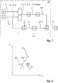
- figure 8 shows a schematic opening duration-closing duration diagram.
- the points shown represent pairwise associated closing and opening durations, for example consecutive.
- a plurality 802 of pairs or points are close together and indicate similar opening and closing behavior for these pairs.
- another point 804 is further away from the plurality 802 of points.
- the determination unit 730 from FIG figure 7 first a mean value m and a variance from the distances d.
- the sum of the mean value m, the variance and an additional fixed or variable offset results in the threshold value d_th.
- An exemplary distance d_804 is greater than the threshold value d_th and thus indicates the presence of the anomaly.
- FIG 9 shows a schematic block diagram.
- the determination of the at least one diagnostic result by means of determination unit 104 includes a determination of a pressure change dP associated with the process medium as a diagnostic result as a function of the at least one acceleration signal a, the at least one acceleration signal a being a plurality of acceleration values a_xy, each of which is one perpendicular to the actuating axis S oriented acceleration of the process valve 200 represent includes.
- the pressure change dP associated with the process medium is determined by a determination unit 902 when a pressure change threshold value a_th, dP_th is exceeded by at least one of the plurality of acceleration values a_xy, which each represent the acceleration of the process valve oriented perpendicular to the actuating axis S.
- the threshold value a_th is determined in advance, for example, and stored in a storage unit 904 .
- Determining the at least one diagnosis result includes determining a pressure change anomaly A_dP as a diagnosis result, in particular a critical pressure surge, as soon as at least one of the plurality of acceleration values a_xy, which each represent the acceleration of the process valve oriented perpendicular to the actuating axis, exceeds that of a plurality of pressure changes dP dependent or exceeds a predetermined pressure change threshold value dP_th.
- the pressure change dP is determined, for example, in the same physical unit as the acceleration values a_xy.
- a plurality of pressure changes dP can thus be stored in a storage unit 910 and compared with acceleration values a_xy.
- the memory unit 910 there are, for example, a number of n pressure changes dP, which are used for further determination. For example, all pressure changes dP that are older than n are discarded.
- the plurality of pressure changes dP is converted into a threshold value dP_th using determination unit 920 .
- a determination unit 930 determines the anomaly A_dP as soon as one of the acceleration values a_xy exceeds the determined threshold value dP_th.
- the pressure change threshold value dP_th is formed as follows, for example during the operation of the process valve. First, an average of the present pressure change threshold values, which were determined, for example, over a predetermined previous period of time, is formed. The mean value is then added with a fixed or variable offset in order to distinguish normal pressure surges in the sense of the pressure change dP from larger pressure surges in the sense of an anomaly during operation.
- figure 10 shows a schematic flowchart to explain the processing of in figure 8 associated closing and opening durations shown in pairs.
- the threshold value d_th is re-determined after each stored pair of values.
- the threshold value d_th is learned or determined in a determination mode according to block 1000:
- the points, ie the pairwise associated closing and opening durations, of the last n switching cycles or m minutes are determined.
- the Euclidean distances between the points are determined.
- the Pythagorean theorem can be used for this.
- the distance between two points is the square root(N ⁇ 2 + O ⁇ 2); with N distance north, E distance east.
- the theorem works in any axis-orthogonal, more-than-zero-dimensional system.
- the threshold value d_th is determined as a function of the distances. For example, the threshold value d_th results from the product: fixed, previously determined factor * maximum distance between two points.
- the threshold value d_th is used.
- a new value/value tuple/point is determined.
- a step 1016 it is determined whether a minimum distance between the newly determined point and the points already determined exceeds the threshold value d_th. If this is the case, then in a step 1018 the anomaly is determined and possibly output.
- a number of up to 0 consecutive anomalies can be discarded until an anomaly is determined and possibly output in order to achieve a certain debouncing. There is then a change back to step 1002.
Landscapes
- Engineering & Computer Science (AREA)
- General Engineering & Computer Science (AREA)
- Mechanical Engineering (AREA)
- Indication Of The Valve Opening Or Closing Status (AREA)
Applications Claiming Priority (1)
| Application Number | Priority Date | Filing Date | Title |
|---|---|---|---|
| DE102021102738.1A DE102021102738A1 (de) | 2021-02-05 | 2021-02-05 | Verfahren und Prozessventil |
Publications (3)
| Publication Number | Publication Date |
|---|---|
| EP4043769A1 true EP4043769A1 (fr) | 2022-08-17 |
| EP4043769C0 EP4043769C0 (fr) | 2024-12-25 |
| EP4043769B1 EP4043769B1 (fr) | 2024-12-25 |
Family
ID=79831644
Family Applications (1)
| Application Number | Title | Priority Date | Filing Date |
|---|---|---|---|
| EP22152352.5A Active EP4043769B1 (fr) | 2021-02-05 | 2022-01-20 | Procede de mesure d'acceleration dans une vanne de processus, et vanne de processus |
Country Status (2)
| Country | Link |
|---|---|
| EP (1) | EP4043769B1 (fr) |
| DE (1) | DE102021102738A1 (fr) |
Citations (6)
| Publication number | Priority date | Publication date | Assignee | Title |
|---|---|---|---|---|
| EP0410317A2 (fr) * | 1989-07-28 | 1991-01-30 | Liberty Technologies, Inc. | Système non-envahissant et méthode pour surveiller des vannes |
| EP0637713A1 (fr) * | 1993-08-05 | 1995-02-08 | Honeywell Ag | Système de diagnostic pour des soupapes de réglage et d'arrêt |
| DE19947129A1 (de) * | 1999-09-30 | 2001-04-05 | Siemens Ag | Diagnosesystem und -verfahren, insbesondere für ein Ventil |
| US20020062682A1 (en) * | 1999-05-27 | 2002-05-30 | Siemens Ag | Diagnostic system for a valve that can be actuated by a position controller via a drive |
| US20050126639A1 (en) * | 2002-04-26 | 2005-06-16 | Siemens Aktiengesellschaft | Diagnostic system and method for a valve |
| US20060254357A1 (en) * | 2003-05-16 | 2006-11-16 | Wolfgang Ens | Diagnostic system and method for a valve, especially a check valve of a positive displacement pump |
Family Cites Families (4)
| Publication number | Priority date | Publication date | Assignee | Title |
|---|---|---|---|---|
| DE19521499C2 (de) | 1995-06-13 | 1997-04-24 | Richter Albert Ari Armaturen | Verfahren und Vorrichtung zur Dämpfung des Ventilhubes an federbelasteten Ventilen |
| US10996236B2 (en) | 2014-07-22 | 2021-05-04 | Fisher Controls International Llc | Control device position feedback with accelerometer |
| DE102018109865A1 (de) | 2018-04-24 | 2019-10-24 | Samson Aktiengesellschaft | Verfahren zum Überwachen der Funktion eines Stellventils, Vorrichtung zur Durchführung eines solchen Verfahrens sowie Stellventil mit einer solchen Vorrichtung |
| BR112021010776A2 (pt) | 2018-12-06 | 2021-08-31 | Bray International, Inc. | Adaptador de válvula inteligente com componentes eletrônicos integrados |
-
2021
- 2021-02-05 DE DE102021102738.1A patent/DE102021102738A1/de active Pending
-
2022
- 2022-01-20 EP EP22152352.5A patent/EP4043769B1/fr active Active
Patent Citations (6)
| Publication number | Priority date | Publication date | Assignee | Title |
|---|---|---|---|---|
| EP0410317A2 (fr) * | 1989-07-28 | 1991-01-30 | Liberty Technologies, Inc. | Système non-envahissant et méthode pour surveiller des vannes |
| EP0637713A1 (fr) * | 1993-08-05 | 1995-02-08 | Honeywell Ag | Système de diagnostic pour des soupapes de réglage et d'arrêt |
| US20020062682A1 (en) * | 1999-05-27 | 2002-05-30 | Siemens Ag | Diagnostic system for a valve that can be actuated by a position controller via a drive |
| DE19947129A1 (de) * | 1999-09-30 | 2001-04-05 | Siemens Ag | Diagnosesystem und -verfahren, insbesondere für ein Ventil |
| US20050126639A1 (en) * | 2002-04-26 | 2005-06-16 | Siemens Aktiengesellschaft | Diagnostic system and method for a valve |
| US20060254357A1 (en) * | 2003-05-16 | 2006-11-16 | Wolfgang Ens | Diagnostic system and method for a valve, especially a check valve of a positive displacement pump |
Also Published As
| Publication number | Publication date |
|---|---|
| DE102021102738A1 (de) | 2022-08-11 |
| EP4043769C0 (fr) | 2024-12-25 |
| EP4043769B1 (fr) | 2024-12-25 |
Similar Documents
| Publication | Publication Date | Title |
|---|---|---|
| EP1256154B1 (fr) | Procede pour surveiller et reguler electroniquement un processus de deplacement de pieces mobiles | |
| DE10335904B4 (de) | Verfahren und Vorrichtung zur bidirektionalen Eindraht-Datenübertragung | |
| DE10344088B4 (de) | Funktionsprüfvorrichtung für ein Feldgerät und Verfahren zur Funktionsprüfung eines Feldgeräts und Feldgerät | |
| EP3546763B1 (fr) | Détection des états de maintenance de vannes | |
| DE102005024686A1 (de) | Stellungsregler | |
| WO2001099252A1 (fr) | Procede pour commander le mouvement de reglage d'une partie d'un systeme de fermeture qui est entrainee par un moteur electrique dans un vehicule | |
| EP2659318B1 (fr) | Procédé et dispositif destinés à fournir une information de déplacement, notamment pour détecter le blocage d'un système de fermeture | |
| DE102017118566A1 (de) | Erfassungssystem zur Detektion einer Betätigung bei einer Griffvorrichtung eines Fahrzeuges | |
| EP3575909B1 (fr) | Procédé de surveillance d'une pluralité de systèmes mécaniques | |
| DE102012215214B4 (de) | Verfahren und Vorrichtung zur Bestimmung der Position eines motorgetriebenen Stellteils | |
| WO2014019671A1 (fr) | Procédé de contrôle du fonctionnement d'un système anti-pincement et dispositif de diagnostic | |
| DE20221873U1 (de) | Ventil mit Online-Erfassung von Ventildaten | |
| DE102016208946A1 (de) | Steuervorrichtung und Verfahren zum Erkennen einer Bewegungsbeeinträchtigung in einer Antriebsvorrichtung | |
| DE102016200830A1 (de) | Verfahren und Vorrichtung zur Fehlererkennung einer Winkelerfassungseinrichtung an einer Tür eines Kraftfahrzeugs | |
| DE202005019464U1 (de) | Verstelleinrichtung sowie elektronische Baugruppe | |
| DE102016212140B4 (de) | Elektrisches sicherheits-fensterhebersystem und betriebsverfahren desselben | |
| WO2022167043A1 (fr) | Procédé d'assistance motorisée du mouvement d'une porte de véhicule | |
| DE102006048026A1 (de) | Kraftfahrzeugschloßanordnung | |
| WO2022043302A1 (fr) | Procédé de réglage d'une pièce de réglage sur un véhicule et de mémorisation de courbes de signal et de courbes de valeurs mesurées pour un test ultérieur | |
| DE102015108667A1 (de) | System und Verfahren zum Bestimmen der Position eines von einem Elektromotor angetriebenen beweglichen Teils | |
| DE102019000868B4 (de) | Lastansteuervorrichtung und Lastansteuerverfahren | |
| DE102011118651A1 (de) | Schnell schaltendes Ventil mit Überwachungseinrichtung | |
| EP4043769B1 (fr) | Procede de mesure d'acceleration dans une vanne de processus, et vanne de processus | |
| DE102017211483A1 (de) | Steuereinheit und Verfahren zum automatischen Schließen einer Klappe und/oder Tür | |
| DE102016205325A1 (de) | Stellvorrichtung für ein verstellbares Fahrzeugteil und Verfahren zum Betrieb einer solchen |
Legal Events
| Date | Code | Title | Description |
|---|---|---|---|
| PUAI | Public reference made under article 153(3) epc to a published international application that has entered the european phase |
Free format text: ORIGINAL CODE: 0009012 |
|
| STAA | Information on the status of an ep patent application or granted ep patent |
Free format text: STATUS: THE APPLICATION HAS BEEN PUBLISHED |
|
| AK | Designated contracting states |
Kind code of ref document: A1 Designated state(s): AL AT BE BG CH CY CZ DE DK EE ES FI FR GB GR HR HU IE IS IT LI LT LU LV MC MK MT NL NO PL PT RO RS SE SI SK SM TR |
|
| STAA | Information on the status of an ep patent application or granted ep patent |
Free format text: STATUS: REQUEST FOR EXAMINATION WAS MADE |
|
| 17P | Request for examination filed |
Effective date: 20230216 |
|
| RBV | Designated contracting states (corrected) |
Designated state(s): AL AT BE BG CH CY CZ DE DK EE ES FI FR GB GR HR HU IE IS IT LI LT LU LV MC MK MT NL NO PL PT RO RS SE SI SK SM TR |
|
| GRAP | Despatch of communication of intention to grant a patent |
Free format text: ORIGINAL CODE: EPIDOSNIGR1 |
|
| STAA | Information on the status of an ep patent application or granted ep patent |
Free format text: STATUS: GRANT OF PATENT IS INTENDED |
|
| INTG | Intention to grant announced |
Effective date: 20240726 |
|
| GRAS | Grant fee paid |
Free format text: ORIGINAL CODE: EPIDOSNIGR3 |
|
| GRAA | (expected) grant |
Free format text: ORIGINAL CODE: 0009210 |
|
| STAA | Information on the status of an ep patent application or granted ep patent |
Free format text: STATUS: THE PATENT HAS BEEN GRANTED |
|
| AK | Designated contracting states |
Kind code of ref document: B1 Designated state(s): AL AT BE BG CH CY CZ DE DK EE ES FI FR GB GR HR HU IE IS IT LI LT LU LV MC MK MT NL NO PL PT RO RS SE SI SK SM TR |
|
| RAP3 | Party data changed (applicant data changed or rights of an application transferred) |
Owner name: GEMUE GEBR. MUELLER APPARATEBAUGMBH & CO. KOMMANDITGESELLSCHAFT |
|
| REG | Reference to a national code |
Ref country code: GB Ref legal event code: FG4D Free format text: NOT ENGLISH |
|
| REG | Reference to a national code |
Ref country code: CH Ref legal event code: EP |
|
| REG | Reference to a national code |
Ref country code: DE Ref legal event code: R096 Ref document number: 502022002460 Country of ref document: DE |
|
| REG | Reference to a national code |
Ref country code: IE Ref legal event code: FG4D Free format text: LANGUAGE OF EP DOCUMENT: GERMAN |
|
| U01 | Request for unitary effect filed |
Effective date: 20250109 |
|
| U07 | Unitary effect registered |
Designated state(s): AT BE BG DE DK EE FI FR IT LT LU LV MT NL PT RO SE SI Effective date: 20250114 |
|
| U20 | Renewal fee for the european patent with unitary effect paid |
Year of fee payment: 4 Effective date: 20250121 |
|
| PG25 | Lapsed in a contracting state [announced via postgrant information from national office to epo] |
Ref country code: HR Free format text: LAPSE BECAUSE OF FAILURE TO SUBMIT A TRANSLATION OF THE DESCRIPTION OR TO PAY THE FEE WITHIN THE PRESCRIBED TIME-LIMIT Effective date: 20241225 |
|
| PG25 | Lapsed in a contracting state [announced via postgrant information from national office to epo] |
Ref country code: NO Free format text: LAPSE BECAUSE OF FAILURE TO SUBMIT A TRANSLATION OF THE DESCRIPTION OR TO PAY THE FEE WITHIN THE PRESCRIBED TIME-LIMIT Effective date: 20250325 |
|
| PG25 | Lapsed in a contracting state [announced via postgrant information from national office to epo] |
Ref country code: GR Free format text: LAPSE BECAUSE OF FAILURE TO SUBMIT A TRANSLATION OF THE DESCRIPTION OR TO PAY THE FEE WITHIN THE PRESCRIBED TIME-LIMIT Effective date: 20250326 |
|
| PG25 | Lapsed in a contracting state [announced via postgrant information from national office to epo] |
Ref country code: RS Free format text: LAPSE BECAUSE OF FAILURE TO SUBMIT A TRANSLATION OF THE DESCRIPTION OR TO PAY THE FEE WITHIN THE PRESCRIBED TIME-LIMIT Effective date: 20250325 |
|
| PG25 | Lapsed in a contracting state [announced via postgrant information from national office to epo] |
Ref country code: SM Free format text: LAPSE BECAUSE OF FAILURE TO SUBMIT A TRANSLATION OF THE DESCRIPTION OR TO PAY THE FEE WITHIN THE PRESCRIBED TIME-LIMIT Effective date: 20241225 |
|
| PG25 | Lapsed in a contracting state [announced via postgrant information from national office to epo] |
Ref country code: PL Free format text: LAPSE BECAUSE OF FAILURE TO SUBMIT A TRANSLATION OF THE DESCRIPTION OR TO PAY THE FEE WITHIN THE PRESCRIBED TIME-LIMIT Effective date: 20241225 |
|
| PG25 | Lapsed in a contracting state [announced via postgrant information from national office to epo] |
Ref country code: ES Free format text: LAPSE BECAUSE OF FAILURE TO SUBMIT A TRANSLATION OF THE DESCRIPTION OR TO PAY THE FEE WITHIN THE PRESCRIBED TIME-LIMIT Effective date: 20241225 |
|
| PG25 | Lapsed in a contracting state [announced via postgrant information from national office to epo] |
Ref country code: IS Free format text: LAPSE BECAUSE OF FAILURE TO SUBMIT A TRANSLATION OF THE DESCRIPTION OR TO PAY THE FEE WITHIN THE PRESCRIBED TIME-LIMIT Effective date: 20250425 |
|
| PG25 | Lapsed in a contracting state [announced via postgrant information from national office to epo] |
Ref country code: SK Free format text: LAPSE BECAUSE OF FAILURE TO SUBMIT A TRANSLATION OF THE DESCRIPTION OR TO PAY THE FEE WITHIN THE PRESCRIBED TIME-LIMIT Effective date: 20241225 |
|
| PG25 | Lapsed in a contracting state [announced via postgrant information from national office to epo] |
Ref country code: CZ Free format text: LAPSE BECAUSE OF FAILURE TO SUBMIT A TRANSLATION OF THE DESCRIPTION OR TO PAY THE FEE WITHIN THE PRESCRIBED TIME-LIMIT Effective date: 20241225 |
|
| REG | Reference to a national code |
Ref country code: CH Ref legal event code: PL |
|
| PG25 | Lapsed in a contracting state [announced via postgrant information from national office to epo] |
Ref country code: MC Free format text: LAPSE BECAUSE OF FAILURE TO SUBMIT A TRANSLATION OF THE DESCRIPTION OR TO PAY THE FEE WITHIN THE PRESCRIBED TIME-LIMIT Effective date: 20241225 |
|
| PG25 | Lapsed in a contracting state [announced via postgrant information from national office to epo] |
Ref country code: CH Free format text: LAPSE BECAUSE OF NON-PAYMENT OF DUE FEES Effective date: 20250131 |
|
| PLBE | No opposition filed within time limit |
Free format text: ORIGINAL CODE: 0009261 |
|
| STAA | Information on the status of an ep patent application or granted ep patent |
Free format text: STATUS: NO OPPOSITION FILED WITHIN TIME LIMIT |
|
| 26N | No opposition filed |
Effective date: 20250926 |
|
| PG25 | Lapsed in a contracting state [announced via postgrant information from national office to epo] |
Ref country code: IE Free format text: LAPSE BECAUSE OF NON-PAYMENT OF DUE FEES Effective date: 20250120 |
|
| U20 | Renewal fee for the european patent with unitary effect paid |
Year of fee payment: 5 Effective date: 20260119 |