EP0410328A1 - Fugenband mit Versteifungselementen - Google Patents
Fugenband mit Versteifungselementen Download PDFInfo
- Publication number
- EP0410328A1 EP0410328A1 EP90113993A EP90113993A EP0410328A1 EP 0410328 A1 EP0410328 A1 EP 0410328A1 EP 90113993 A EP90113993 A EP 90113993A EP 90113993 A EP90113993 A EP 90113993A EP 0410328 A1 EP0410328 A1 EP 0410328A1
- Authority
- EP
- European Patent Office
- Prior art keywords
- profile
- profile strand
- stiffening elements
- joint tape
- tape according
- Prior art date
- Legal status (The legal status is an assumption and is not a legal conclusion. Google has not performed a legal analysis and makes no representation as to the accuracy of the status listed.)
- Granted
Links
- 238000007789 sealing Methods 0.000 claims abstract description 7
- 239000004033 plastic Substances 0.000 claims abstract description 5
- 238000010276 construction Methods 0.000 claims abstract description 4
- 239000000463 material Substances 0.000 claims description 11
- 239000011324 bead Substances 0.000 claims description 9
- 230000007704 transition Effects 0.000 claims description 2
- XLYOFNOQVPJJNP-UHFFFAOYSA-N water Substances O XLYOFNOQVPJJNP-UHFFFAOYSA-N 0.000 description 5
- 230000000694 effects Effects 0.000 description 4
- 238000004519 manufacturing process Methods 0.000 description 4
- 238000010924 continuous production Methods 0.000 description 3
- 238000001125 extrusion Methods 0.000 description 3
- 238000000034 method Methods 0.000 description 3
- 229910000831 Steel Inorganic materials 0.000 description 2
- 230000000717 retained effect Effects 0.000 description 2
- 239000010959 steel Substances 0.000 description 2
- 239000002318 adhesion promoter Substances 0.000 description 1
- 239000011248 coating agent Substances 0.000 description 1
- 238000000576 coating method Methods 0.000 description 1
- 239000013013 elastic material Substances 0.000 description 1
- 239000002184 metal Substances 0.000 description 1
- 239000007921 spray Substances 0.000 description 1
Images
Classifications
-
- E—FIXED CONSTRUCTIONS
- E04—BUILDING
- E04B—GENERAL BUILDING CONSTRUCTIONS; WALLS, e.g. PARTITIONS; ROOFS; FLOORS; CEILINGS; INSULATION OR OTHER PROTECTION OF BUILDINGS
- E04B1/00—Constructions in general; Structures which are not restricted either to walls, e.g. partitions, or floors or ceilings or roofs
- E04B1/62—Insulation or other protection; Elements or use of specified material therefor
- E04B1/66—Sealings
- E04B1/68—Sealings of joints, e.g. expansion joints
- E04B1/6806—Waterstops
Definitions
- the present invention relates to a joint tape for sealing butt joints in concrete construction, consisting of an extruded profile strand made of plastic or rubber with strip-shaped stiffening elements running at right angles to the longitudinal direction of the profile.
- Such a joint tape is known from DE-PS 30 11 225.
- the stiffening elements are completely embedded in the profile strand in such a way that the joint tape has the same cross-section throughout the longitudinal direction of the profile. Due to this embedding of the stiffening elements, however, the profile strand must be made very thick overall, which leads to a disadvantageously high material consumption and thus to high manufacturing costs.
- Another joint tape is known from DE-OS 24 08 514.
- the stiffening elements are formed by bent steel wires on one side are arranged "outside" of the profile strand.
- the steel wires have a straight middle part which is in contact with the profile strand and two curved end sections which surround and clamp the edge of the profile strand.
- the stiffening elements are consequently not embedded here, so that the profile strand can be made thinner, which leads to reduced material consumption.
- the disadvantage here is that the stiffening elements surrounding the joint tape on the outside can represent bridges for waterways and, moreover, significantly increase the production costs, since continuous production of this joint tape is difficult because the stiffening elements have to be clamped individually by hand. There is also the risk that the stiffening elements fixed on the outside of the joint tape will be lost during transport and / or at the construction site itself.
- the present invention is therefore based on the object of creating a joint tape of the generic type in which the profile strand can be made thinner and thus less expensive by material, but the stiffening elements should nevertheless be firmly connected to the profile strand and water bridging via the stiffening elements is avoided.
- a simple, inexpensive, continuous production of the joint tape should also be possible.
- stiffening elements are each partially embedded in the profile strand in the region of their two ends and extend over a surface of the profile strand in the region lying between the embedded ends.
- the profile strand can be made practically arbitrarily thin in its area lying between the embedded ends of the stiffening elements, which enables the desired material saving. Nevertheless, the stiffening elements are firmly, captively connected to the profile strand.
- the simple and inexpensive producibility of the joint tape according to the invention is also particularly advantageous, the stiffening elements being molded in regions during the extrusion process of the profile strand. As a result, the joint tape according to the invention can be produced continuously in only one operation.
- the stiffening elements each form a water bridge in their area lying between the embedded ends, the so-called water circulation path is advantageously interrupted by the end-side embedding of the stiffening elements.
- the sealing function effected by edge beads of the profile strand according to the so-called labyrinth principle is fully retained.
- a joint tape 2 consists of an extruded profile strand 4 made of an elastic material, such as plastic or rubber (rubber).
- the profile strand 4 has a thickened edge bead 6 on each of its two longitudinal edges. These edge beads 6 cause an extension or interruption of the water circulation path to avoid water cross bridges.
- a positive connection between the joint tape 2 and the concrete enclosing it is also achieved by the edge beads 6.
- the joint tape 2 also has a plurality of strip-shaped stiffening elements 8 which run transversely to the longitudinal direction of the profile and are spaced apart from one another and preferably have a flat, rectangular cross section.
- the stiffening elements 8 can have a width of 5 to 8 mm and a thickness of 1 to 1.5 mm.
- the mutual distance of the stiffening elements 8 from one another is advantageously 10 to 15 cm.
- the stiffening elements 8 suitably consist of metal or a rigid plastic, for example hard PVC.
- the stiffening elements 8 serve to stiffen the joint tape 2 in the transverse direction in such a way that it can always be laid out flat.
- the stiffening elements 8 are now only partially embedded in the profile strand 4 in the area of their two ends 10. Im between the embedded Stiffening elements 8 advantageously lie essentially at the ends 10 of the area 10 of the profile strand 4. In the exemplary embodiment shown, the stiffening elements 8 lie directly on the surface 12 of the profile strand 4. However, it is also possible that the stiffening elements 8 are integrally connected to the profile strand 4 in this area or, due to the production of the joint tape 2 in the extrusion process, at least partially stick to the profile strand 4 superficially.
- the profile strand 4 has ribs 16 running in the longitudinal direction of the profile on its side 14 opposite the stiffening elements 8. These ribs 16 also serve to improve the sealing effect of the joint tape according to the invention and also for a positive connection between the joint tape 2 and the concrete.
- the stiffening elements 8 i.e. on the surface 12, on the other hand, there is no need for such ribs, since these would be bridged by the stiffening elements 8 anyway.
- the surface 12 can therefore be formed without profiling.
- the ends 10 of the stiffening elements 8 according to the invention are embedded in retaining ribs 18 formed on the surface 12 of the profile strand 4 and extending in the profile longitudinal direction.
- These holding ribs 18 are expediently formed in the transition area between one of the thickened edge beads 6 and the surface 12 of the profile strand 4.
- At least one further rib 20 is formed in each case in the region of the holding ribs 18.
- the embedded ends 10 of the stiffening elements 8 are also connected to the profile strand 4 in a material and / or form-fitting manner.
- the stiffening elements 8 each have at least one through hole 22 in their embedded ends 10 through which the material of the profile strand 4 or the holding ribs 18 extends in a form-fitting manner.
- form-fitting material through connections 24 are formed in the area of the through holes 8.
- a material connection can be provided in the area of the ends 10, for example via an adhesion promoter coating. It is also possible to vulcanize the stiffening elements 8 in the region of the ends 10 into the profile strand 4, which then consists of rubber.
- the profile strand 4 is connected to an edge strip 26 in the region of at least one longitudinal edge, ie in particular following the edge bead 6, this edge strip 26 having through holes 28 spaced apart from one another in the profile longitudinal direction.
- the joint tape 2 preferably has an edge strip 26 on both edges.
- This edge strip according to the invention is used to fix the joint tape 2 before concreting, by pulling a binding or string wire 30 through the eyelet-like through holes 28, whereby then the ends of the wire 30 are braced and fastened, for example, to a wooden casing.
- the edge strip 26 is cohesive, in particular homogeneous, i.e. Uniform material, is connected to the profile strand 4. It is particularly expedient here if the profile strand 4 is made of soft PVC and the edge strip 26 is made of hard PVC, since these materials can be homogeneously connected to one another, in particular during the extrusion process. This also ensures on the one hand a necessary elasticity of the joint tape 2 or the profile strand 4, but on the other hand also ensures sufficient strength of the edge strip 26, wherein tearing out of the through holes 28 by tensile forces applied via the wire 30 is advantageously almost impossible.
- the production of the joint tape 2 according to the invention is advantageously very simple and therefore inexpensive.
- the profile strand 4 and on the other hand the retaining ribs 18 are expediently extruded first, but then brought together in a common extruder or spray head, including the stiffening elements 8, and thus connected in a material-uniform, homogeneous manner by embedding the ends 10 of the stiffening elements 8.
- This allows continuous production, with the stiffening elements 8 being able to be fed automatically, in cycles.
Landscapes
- Engineering & Computer Science (AREA)
- Architecture (AREA)
- Physics & Mathematics (AREA)
- Electromagnetism (AREA)
- Civil Engineering (AREA)
- Structural Engineering (AREA)
- Building Environments (AREA)
- Cable Accessories (AREA)
- Adhesive Tapes (AREA)
- Bridges Or Land Bridges (AREA)
Abstract
Description
- Die vorliegende Erfindung betrifft ein Fugenband zum Abdichten von Stoßfugen im Betonbau, bestehend aus einem extrudierten Profilstrang aus Kunststoff oder Kautschuk mit quer zur Profillängsrichtung verlaufenden, im Abstand voneinander angeordneten, streifenförmigen Versteifungselementen.
- Ein derartiges Fugenband ist aus der DE-PS 30 11 225 bekannt. Bei diesem Fugenband sind die Versteifungselemente vollständig in den Profilstrang derart eingebettet, daß das Fugenband in Profillängsrichtung durchgehend den gleichen Querschnitt aufweist. Aufgrund dieser Einbettung der Versteifungselemente muß der Profilstrang jedoch insgesamt sehr dick ausgebildet werden, was zu einem nachteilig hohen Materialverbrauch und damit zu hohen Herstellungskosten führt.
- Ein weiteres Fugenband ist aus der DE-OS 24 08 514 bekannt. Bei diesem bekannten Fugenband sind die Versteifungselemente von gebogenen Stahldrähten gebildet, die auf einer Seite "außerhalb" des Profilstranges angeordnet sind. Die Stahldrähte besitzen einen geraden, am Profilstrang anliegenden Mittelteil und zwei gebogene, Randwulste des Profilstranges klemmend umfassende Endabschnitte. Die Versteifungselemente sind hier folglich nicht eingebettet, so daß der Profilstrang dünner ausgebiIdet werden kann, was zu einem reduzierten Materialverbrauch führt. Nachteilig hierbei ist jedoch, daß die das Fugenband außen umschließenden Versteifungselemente Brücken für Wasserwege darstellen können und darüber hinaus die Fertigungskosten wesentlich erhöhen, da eine kontinuierliche Fertigung dieses Fugenbandes nur schwer möglich ist, weil die Versteifungselemente einzeln von Hand aufgeklemmt werden müssen. Weiterhin besteht die Gefahr, daß die außen am Fugenband festgelegten Versteifungselemente während des Transportes und/oder an der Baustelle selbst verlorengehen.
- Der vorliegenden Erfindung liegt daher die Aufgabe zugrunde, ein Fugenband der gattungsgemäßen Art zu schaffen, bei dem der Profilstrang dünner und damit durch eingespartes Material preiswerter gefertigt werden kann, wobei aber dennoch die Versteifungselemente fest mit dem Profilstrang verbunden sein sollen und eine Wasserbrückenbildung über die Versteifungselemente vermieden wird. Zudem soll auch eine einfache, preiswerte, kontinuierliche Fertigung des Fugenbandes möglich sein.
- Erfindungsgemäß wird dies dadurch erreicht, daß die Versteifungselemente jeweils im Bereich ihrer beiden Enden bereichsweise in den Profilstrang eingebettet sind und im zwischen den eingebetteten Enden liegenden Bereich über eine Oberfläche des Profilstranges verlaufen.
- Durch diese vorteilhafte Ausgestaltung kann der Profilstrang in seinem zwischen den eingebetteten Enden der Versteifungselemente liegenden Bereich praktisch beliebig dünn ausgebildet werden, was die angestrebte Materialeinsparung ermöglicht. Dennoch sind die Versteifungselemente fest, unverlierbar mit dem Profilstrang verbunden. Von besonderem Vorteil ist dabei auch die einfache und preiswerte Herstellbarkeit des erfindungsgemäßen Fugenbandes, wobei die Versteifungselemente während des Extrusionsvorganges des Profilstranges bereichsweise eingeformt werden. Hierdurch kann das erfindungsgemäße Fugenband kontinuierlich in nur einem Arbeitsgang hergestellt werden.
- Die Versteifungselemente bilden zwar jeweils in ihrem zwischen den eingebetteten Enden liegenden Bereich eine Wasserbrücke, jedoch wird der sogenannte Wasserumlaufweg durch die endseitige Einbettung der Versteifungselemente vorteilhafterweise unterbrochen. Hierdurch bleibt insbesondere die durch Randwulste des Profilstranges bewirkte Dichtungsfunktion nach dem sogenannten Labyrinthprinzip voll erhalten.
- Weitere vorteilhafte Ausgestaltungsmerkmale der Erfindung sind in den Unteransprüchen sowie der folgenden Beschreibung enthalten.
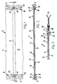
- Anhand der Zeichnung soll im folgenden die Erfindung beispielhaft näher erläutert werden. Dabei zeigen:
- Fig. 1 eine Draufsicht eines Abschnittes eines erfindungsgemäßen Fugenbandes auf die Seite der Versteifungselemente,
- Fig. 2 einen Querschnitt durch das erfindungsgemäße Fugenband im Bereich eines Versteifungselementes längs der Schnittlinie II-II in Fig. 1 und
- Fig. 3 eine Teilansicht analog zu Fig. 2 in einer vorteilhaften Weiterbildung des erfindungsgemäßen Fugenbandes.
- In den verschiedenen Zeichnungsfiguren sind gleiche Teile stets mit den gleichen Bezugsziffern bezeichnet.
- Ein erfindungsgemäßes Fugenband 2 besteht aus einem extrudierten Profilstrang 4 aus einem elastischen Material, wie Kunststoff oder Kautschuk (Gummi). Der Profilstrang 4 besitzt an seinen beiden Längskanten jeweils einen verdickten Randwulst 6. Diese Randwulste 6 bewirken eine Verlängerung bzw. Unterbrechung des Wasserumlaufweges zur Vermeidung von Wasserquerbrücken. Darüber hinaus wird durch die Randwulste 6 auch eine formschlüssige Verbindung zwischen dem Fugenband 2 und dem dieses einschließenden Beton erreicht. Das Fugenband 2 besitzt weiterhin mehrere quer zur Profillängsrichtung verlaufende, im Abstand voneinander angeordnete, streifenförmige Versteifungselemente 8 mit vorzugsweise flachem, rechteckigem Querschnitt. Beispielsweise können die Versteifungselemente 8 eine Breite von 5 bis 8 mm und eine Dicke von 1 bis 1,5 mm aufweisen. Der gegenseitige Abstand der Versteifungselemente 8 voneinander beträgt zweckmäßigerweise 10 bis 15 cm. Die Versteifungselemente 8 bestehen zweckmäßigerweise aus Metall oder einem starren Kunststoff, beispielsweise Hart-PVC. Die Versteifungselemente 8 dienen dazu, das Fugenband 2 in Querrichtung derart zu versteifen, daß es sich stets plan auslegen läßt.
- Erfindungsgemäß sind nun die Versteifungselemente 8 jeweils nur im Bereich ihrer beiden Enden 10 bereichsweise in den Profilstrang 4 eingebettet. Im zwischen den eingebetteten Enden 10 liegenden Bereich verlaufen die Versteifungselemente 8 vorteilhafterweise im wesentlichen bindungsfrei über eine Oberfläche 12 des Profilstranges 4. Im dargestellten Ausführungsbeispiel liegen die Versteifungselemente 8 unmittelbar auf der Oberfläche 12 des Profilstranges 4 auf. Dabei ist es allerdings auch möglich, daß die Versteifungselemente 8 in diesem Bereich mit dem Profilstrang 4 stoffschlüssig verbunden sind bzw. bedingt durch die Herstellung des Fugenbandes 2 im Extrusionsverfahren zumindest bereichsweise an dem Profilstrang 4 oberflächlich haften.
- Besonders in Fig. 2 ist zu erkennen, daß durch die erfindungsgemäße Ausgestaltung die Dichtungswirkung der Randwulste 6 voll erhalten bleibt. Zudem ist es vorteilhaft, wenn der Profilstrang 4 auf seiner den Versteifungselementen 8 gegenüberliegenden Seite 14 in Profillängsrichtung verlaufende Rippen 16 aufweist. Auch diese Rippen 16 dienen zur Verbesserung der Dichtungswirkung des erfindungsgemäßen Fugenbandes sowie auch zu einem Formschluß zwischen dem Fugenband 2 und dem Beton. Auf der Seite der Versteifungselemente 8, d.h. auf der Oberfläche 12, erübrigen sich dagegen derartige Rippen, da diese ohnehin von den Versteifungselementen 8 überbrückt werden würden. Die Oberfläche 12 kann daher ohne Profilierung ausgebildet werden.
- Wie ebenfalls am besten in Fig. 2, aber auch in Fig. 3 zu erkennen ist, sind die Enden 10 der Versteifungselemente 8 erfindungsgemäß in auf der Oberfläche 12 des Profilstranges 4 gebildeten, in Profillängsrichtung verlaufenden Halterippen 18 eingebettet. Dabei sind diese Halterippen 18 zweckmäßigerweise jeweils im Übergangsbereich zwischen einem der verdickten Randwulste 6 und der Oberfläche 12 des Profilstranges 4 gebildet.
- Zur weiteren Verbesserung der Dichtungswirkung des erfindungsgemäßen Fugenbandes 2 ist es besonders vorteilhaft, wenn im Bereich der Halterippen 18 jeweils mindestens eine weitere Rippe 20 gebildet ist.
- In der dargestellten, bevorzugten Ausführungsform der Erfindung sind weiterhin die eingebetteten Enden 10 der Versteifungselemente 8 stoff- und/oder formschlüssig mit dem Profilstrang 4 verbunden. Insbesondere weisen die Versteifungselemente 8 in ihren eingebetteten Enden 10 jeweils mindestens ein Durchgangsloch 22 auf, durch das sich das Material des Profilstranges 4 bzw. der Halterippen 18 formschlüssig erstreckt. Hierdurch werden - wie in Fig. 2 und 3 zu erkennen ist - im Bereich der Durchgangslöcher 8 formschlüssige Materialdurchverbindungen 24 gebildet. Zusätzlich zu dieser formschlüssigen Verbindung oder aber alternativ hierzu kann eine stoffschlüssige Verbindung im Bereich der Enden 10 beispielsweise über eine Haftvermittlerbeschichtung vorgesehen sein. Ebenfalls ist es möglich, die Versteifungselemente 8 im Bereich der Enden 10 in den dann aus Kautschuk bestehenden Profilstrang 4 einzuvulkanisieren.
- In Fig. 3 ist noch eine vorteilhafte Weiterbildung der Erfindung dargestellt. In dieser Ausführung ist der Profilstrang 4 im Bereich mindestens eines Längsrandes, d.h. insbesondere im Anschluß an den Randwulst 6, mit einem Randstreifen 26 verbunden, wobei dieser Randstreifen 26 in Profillängsrichtung voneinander beabstandete Durchgangslöcher 28 aufweist. Vorzugsweise besitzt das Fugenband 2 an beiden Rändern jeweils einen Randstreifen 26. Dieser erfindungsgemäße Randstreifen dient zum Fixieren des Fugenbandes 2 vor dem Betonieren, indem durch die ösenartigen Durchgangslöcher 28 ein Binde- oder Rödeldraht 30 gezogen wird, wobei dann die Enden des Drahtes 30 abgespannt und beispielsweise an einer Holzverschalung befestigt werden.
- Zur Gewährleistung einer festen, dauerhaften Verbindung zwischen dem Profilstrang 4 und dem Randstreifen 26 ist es erfindungsgemäß vorgesehen, daß der Randstreifen 26 stoffschlüssig, und zwar insbesondere homogen, d.h. materialeinheitlich, mit dem Profilstrang 4 verbunden ist. Hierbei ist es besonders zweckmäßig, wenn der Profilstrang 4 aus Weich-PVC und der Randstreifen 26 aus Hart-PVC bestehen, da sich diese Materialien insbesondere während des Extrusionsvorganges homogen miteinander verbinden lassen. Hierdurch ist zudem einerseits eine erforderliche Elastizität des Fugenbandes 2 bzw. des Profilstranges 4, andererseits aber auch eine ausreichende Festigkeit des Randstreifens 26 gewährleistet, wobei ein Ausreißen der Durchgangslöcher 28 durch über den Draht 30 aufgebrachte Zugkräfte vorteilhafterweise nahezu ausgeschlossen ist.
- Die Herstellung des erfindungsgemäßen Fugenbandes 2 ist vorteilhafterweise sehr einfach und damit preiswert. Hierzu werden zweckmäßigerweise zunächst einerseits der Profilstrang 4 und andererseits die Halterippen 18 jeweils gesondert extrudiert, dann aber in einem gemeinsamen Extruder- bzw. Spritzkopf unter Einschluß der Versteifungselemente 8 zusammengeführt und so materialeinheitlich, homogen unter Einbettung der Enden 10 der Versteifungselemente 8 verbunden. Dies gestattet eine kontinuierliche Fertigung, wobei die Versteifungselemente 8 automatisch, taktweise zugeführt werden können.
- Die Erfindung ist nicht auf die dargestellten und beschriebenen Ausführungsformen beschränkt, sondern umfaßt auch alle im Sinne der Erfindung gleichwirkenden Merkmale.
Claims (9)
dadurch gekennzeichnet, daß die Versteifungselemente (8) jeweils im Bereich ihrer beiden Enden (10) bereichsweise in den Profilstrang (4) eingebettet sind und im zwischen den eingebetteten Enden (10) liegenden Bereich über eine Oberfläche (12) des Profilstranges (4) verlaufen.
dadurch gekennzeichnet, daß die Enden (10) der vorzugweise auf der Oberfläche (12) des Profilstranges (4) aufliegenden Versteifungselemente (8) in auf der Oberfläche (12) des Profilstranges (4) gebildeten, in Profillängsrichtung verlaufenden Halterippen (18) eingebettet sind.
dadurch gekennzeichnet, daß die Halterippen (18) jeweils im Übergangsbereich zwischen einem verdickten Randwulst (6) des Profilstranges (4) und der Oberfläche (12) des Profilstranges (4) gebildet sind.
dadurch gekennzeichnet, daß die eingebetteten Enden (10) der Versteifungselemente (8) stoff- und/oder formschlüssig mit dem Profilstrang (4) verbunden sind.
dadurch gekennzeichnet, daß die Versteifungselemente (8) in ihren eingebetteten Enden (10) jeweils mindestens ein Durchgangsloch (22) aufweisen, durch das sich das Material des Profilstranges (4) formschlüssig erstreckt.
dadurch gekennzeichnet, daß der Profilstrang (4) auf seiner den Versteifungselementen (8) gegenüberliegenden Seite (14) in Profillängsrichtung verlaufende Rippen (16) oder dergleichen Profilierung aufweist.
dadurch gekennzeichnet, daß auf den Halterippen (18) jeweils mindestens eine in Profillängsrichtung verlaufende Rippe (20) oder dergleichen Profilierung gebildet ist.
dadurch gekennzeichnet, daß der Profilstrang (4) an mindestens einem seiner Längsränder, insbesondere im Anschluß an den Randwulst (6), mit einem Randstreifen (26) verbunden ist, wobei der Randstreifen (26) in Profillängsrichtung voneinander beabstandete Durchgangslöcher (28) aufweist.
dadurch gekennzeichnet, daß der Randstreifen (26) stoffschlüssig, insbesondere homogen, materialeinheitlich mit dem Profilstrang (4) verbunden ist, wobei vorzugsweise der Profilstrang (4) aus Weich-PVC und der Randstreifen (26) aus Hart-PVC bestehen.
Priority Applications (1)
| Application Number | Priority Date | Filing Date | Title |
|---|---|---|---|
| AT90113993T ATE86333T1 (de) | 1989-07-25 | 1990-07-21 | Fugenband mit versteifungselementen. |
Applications Claiming Priority (2)
| Application Number | Priority Date | Filing Date | Title |
|---|---|---|---|
| DE3924498 | 1989-07-25 | ||
| DE3924498A DE3924498A1 (de) | 1989-07-25 | 1989-07-25 | Fugenband mit versteifungselementen |
Publications (2)
| Publication Number | Publication Date |
|---|---|
| EP0410328A1 true EP0410328A1 (de) | 1991-01-30 |
| EP0410328B1 EP0410328B1 (de) | 1993-03-03 |
Family
ID=6385731
Family Applications (1)
| Application Number | Title | Priority Date | Filing Date |
|---|---|---|---|
| EP90113993A Expired - Lifetime EP0410328B1 (de) | 1989-07-25 | 1990-07-21 | Fugenband mit Versteifungselementen |
Country Status (5)
| Country | Link |
|---|---|
| EP (1) | EP0410328B1 (de) |
| AT (1) | ATE86333T1 (de) |
| DE (2) | DE3924498A1 (de) |
| DK (1) | DK0410328T3 (de) |
| ES (1) | ES2040007T3 (de) |
Cited By (1)
| Publication number | Priority date | Publication date | Assignee | Title |
|---|---|---|---|---|
| EP4438465A1 (de) * | 2023-03-27 | 2024-10-02 | Airbus Operations GmbH | Dichtleiste, steuerflächenanordnung, flugzeugflügel und flugzeug |
Families Citing this family (1)
| Publication number | Priority date | Publication date | Assignee | Title |
|---|---|---|---|---|
| LU88161A1 (de) * | 1992-08-19 | 1994-04-01 | Arbed | Dichtungsprofil fuer Spundbohlenschloesser |
Citations (5)
| Publication number | Priority date | Publication date | Assignee | Title |
|---|---|---|---|---|
| DE1910807A1 (de) * | 1969-03-04 | 1970-11-26 | Gruenau Gmbh Chem Fab | Fugenband |
| DE1658780A1 (de) * | 1967-10-17 | 1971-04-01 | Abdichtungstechnik Schlott & B | Geteiltes Bodenfugenprofil mit eingelegter Metallschiene |
| FR2169138A1 (de) * | 1972-01-24 | 1973-09-07 | Faleij Karl | |
| US4497762A (en) * | 1982-03-15 | 1985-02-05 | Winfried Meister | Method and apparatus for the production of jointing bands with embedded reinforcing profiles which run at right angles to the longitudinal axis of the band |
| EP0304225A1 (de) * | 1987-08-19 | 1989-02-22 | W.R. Grace Limited | Dichtung |
-
1989
- 1989-07-25 DE DE3924498A patent/DE3924498A1/de not_active Withdrawn
-
1990
- 1990-07-21 ES ES199090113993T patent/ES2040007T3/es not_active Expired - Lifetime
- 1990-07-21 DE DE9090113993T patent/DE59000956D1/de not_active Expired - Lifetime
- 1990-07-21 EP EP90113993A patent/EP0410328B1/de not_active Expired - Lifetime
- 1990-07-21 AT AT90113993T patent/ATE86333T1/de not_active IP Right Cessation
- 1990-07-21 DK DK90113993.1T patent/DK0410328T3/da active
Patent Citations (5)
| Publication number | Priority date | Publication date | Assignee | Title |
|---|---|---|---|---|
| DE1658780A1 (de) * | 1967-10-17 | 1971-04-01 | Abdichtungstechnik Schlott & B | Geteiltes Bodenfugenprofil mit eingelegter Metallschiene |
| DE1910807A1 (de) * | 1969-03-04 | 1970-11-26 | Gruenau Gmbh Chem Fab | Fugenband |
| FR2169138A1 (de) * | 1972-01-24 | 1973-09-07 | Faleij Karl | |
| US4497762A (en) * | 1982-03-15 | 1985-02-05 | Winfried Meister | Method and apparatus for the production of jointing bands with embedded reinforcing profiles which run at right angles to the longitudinal axis of the band |
| EP0304225A1 (de) * | 1987-08-19 | 1989-02-22 | W.R. Grace Limited | Dichtung |
Cited By (1)
| Publication number | Priority date | Publication date | Assignee | Title |
|---|---|---|---|---|
| EP4438465A1 (de) * | 2023-03-27 | 2024-10-02 | Airbus Operations GmbH | Dichtleiste, steuerflächenanordnung, flugzeugflügel und flugzeug |
Also Published As
| Publication number | Publication date |
|---|---|
| DK0410328T3 (da) | 1993-04-05 |
| ATE86333T1 (de) | 1993-03-15 |
| EP0410328B1 (de) | 1993-03-03 |
| ES2040007T3 (es) | 1993-10-01 |
| DE3924498A1 (de) | 1991-01-31 |
| DE59000956D1 (de) | 1993-04-08 |
Similar Documents
| Publication | Publication Date | Title |
|---|---|---|
| DE2437809B2 (de) | Siebboden sowie siebkoerper und rahmen hierfuer | |
| AT389689B (de) | Endloses gelaenderlaufband aus elastischem material | |
| DE2823815C2 (de) | Fenster, vorzugsweise für Kraftfahrzeuge | |
| EP0285925B2 (de) | Dichtungsprofil | |
| EP0180688B1 (de) | Plattenelement mit einer durch eine elastische Auflage abgedeckten Stirnseite | |
| EP0410328B1 (de) | Fugenband mit Versteifungselementen | |
| WO2009049338A1 (de) | Gleiseindeckung | |
| DE3204411C2 (de) | ||
| EP0410347A1 (de) | Fugenband mit verbesserten Montageeigenschaften | |
| DE3629865A1 (de) | Strangfoermiges dichtungsprofil | |
| EP0629262A1 (de) | Dichtungsprofil für tunnelrohrsegmente, insbesondere für einschwimmelemente | |
| DE3018383A1 (de) | Schlauchschelle | |
| DE1755283A1 (de) | Vorrichtung mit einem biegsamen endlosen Antriebsband,insbesondere fuer Fahrzeuge und ortsfeste Anlagen | |
| EP0722052A1 (de) | Antriebsriemen | |
| DE2706277A1 (de) | Siebboden | |
| DE1800353A1 (de) | Raupenband fuer Schneefahrzeuge | |
| DE3436201A1 (de) | Bauteil | |
| AT333830B (de) | Fahrbahnubergang zur uberbruckung von fahrbahnfugen | |
| EP0181607B1 (de) | Vorrichtung zur Befestigung von Schienen einer Eisenbahn auf Y-Stahlschwellen | |
| DE3203022C2 (de) | Schienenverbindung für elektrische Spiel- und Modellbahnen | |
| DE29519544U1 (de) | Sollriß-Fugenschiene für Betonbauten | |
| DE1919138C3 (de) | ||
| DE3309114A1 (de) | Putzprofilleiste | |
| DE2249970C3 (de) | Vorrichtung zum Überbrücken und Abdecken von Dehnungsfugen an Brücken und ähnlichen Bauwerken | |
| DE2759076C2 (de) |
Legal Events
| Date | Code | Title | Description |
|---|---|---|---|
| PUAI | Public reference made under article 153(3) epc to a published international application that has entered the european phase |
Free format text: ORIGINAL CODE: 0009012 |
|
| 17P | Request for examination filed |
Effective date: 19901130 |
|
| AK | Designated contracting states |
Kind code of ref document: A1 Designated state(s): AT BE CH DE DK ES FR GB GR IT LI LU NL SE |
|
| 17Q | First examination report despatched |
Effective date: 19910926 |
|
| GRAA | (expected) grant |
Free format text: ORIGINAL CODE: 0009210 |
|
| AK | Designated contracting states |
Kind code of ref document: B1 Designated state(s): AT BE CH DE DK ES FR GB GR IT LI LU NL SE |
|
| PG25 | Lapsed in a contracting state [announced via postgrant information from national office to epo] |
Ref country code: GR Free format text: LAPSE BECAUSE OF FAILURE TO SUBMIT A TRANSLATION OF THE DESCRIPTION OR TO PAY THE FEE WITHIN THE PRESCRIBED TIME-LIMIT Effective date: 19930303 |
|
| REF | Corresponds to: |
Ref document number: 86333 Country of ref document: AT Date of ref document: 19930315 Kind code of ref document: T |
|
| ITF | It: translation for a ep patent filed | ||
| REG | Reference to a national code |
Ref country code: DK Ref legal event code: T3 |
|
| GBT | Gb: translation of ep patent filed (gb section 77(6)(a)/1977) |
Effective date: 19930304 |
|
| REF | Corresponds to: |
Ref document number: 59000956 Country of ref document: DE Date of ref document: 19930408 |
|
| ET | Fr: translation filed | ||
| REG | Reference to a national code |
Ref country code: ES Ref legal event code: FG2A Ref document number: 2040007 Country of ref document: ES Kind code of ref document: T3 |
|
| PLBE | No opposition filed within time limit |
Free format text: ORIGINAL CODE: 0009261 |
|
| STAA | Information on the status of an ep patent application or granted ep patent |
Free format text: STATUS: NO OPPOSITION FILED WITHIN TIME LIMIT |
|
| 26N | No opposition filed | ||
| EPTA | Lu: last paid annual fee | ||
| EAL | Se: european patent in force in sweden |
Ref document number: 90113993.1 |
|
| REG | Reference to a national code |
Ref country code: GB Ref legal event code: IF02 |
|
| REG | Reference to a national code |
Ref country code: CH Ref legal event code: PFA Owner name: FIRMA WINFRIED MEISTER Free format text: FIRMA WINFRIED MEISTER#ROSENTHALSTRASSE 14#WUPPERTAL 21 (DE) -TRANSFER TO- FIRMA WINFRIED MEISTER#ROSENTHALSTRASSE 14#WUPPERTAL 21 (DE) |
|
| PGFP | Annual fee paid to national office [announced via postgrant information from national office to epo] |
Ref country code: FR Payment date: 20090722 Year of fee payment: 20 Ref country code: DK Payment date: 20090729 Year of fee payment: 20 Ref country code: ES Payment date: 20090723 Year of fee payment: 20 |
|
| PGFP | Annual fee paid to national office [announced via postgrant information from national office to epo] |
Ref country code: SE Payment date: 20090729 Year of fee payment: 20 Ref country code: NL Payment date: 20090726 Year of fee payment: 20 Ref country code: LU Payment date: 20090728 Year of fee payment: 20 Ref country code: GB Payment date: 20090722 Year of fee payment: 20 Ref country code: CH Payment date: 20090727 Year of fee payment: 20 Ref country code: AT Payment date: 20090729 Year of fee payment: 20 |
|
| PGFP | Annual fee paid to national office [announced via postgrant information from national office to epo] |
Ref country code: DE Payment date: 20090925 Year of fee payment: 20 |
|
| PGFP | Annual fee paid to national office [announced via postgrant information from national office to epo] |
Ref country code: BE Payment date: 20090729 Year of fee payment: 20 |
|
| PGFP | Annual fee paid to national office [announced via postgrant information from national office to epo] |
Ref country code: IT Payment date: 20090727 Year of fee payment: 20 |
|
| REG | Reference to a national code |
Ref country code: NL Ref legal event code: V4 Effective date: 20100721 |
|
| REG | Reference to a national code |
Ref country code: CH Ref legal event code: PL |
|
| BE20 | Be: patent expired |
Owner name: FIRMA WINFRIED *MEISTER Effective date: 20100721 |
|
| REG | Reference to a national code |
Ref country code: DK Ref legal event code: EUP |
|
| REG | Reference to a national code |
Ref country code: GB Ref legal event code: PE20 Expiry date: 20100720 |
|
| REG | Reference to a national code |
Ref country code: ES Ref legal event code: FD2A Effective date: 20100722 |
|
| EUG | Se: european patent has lapsed | ||
| PG25 | Lapsed in a contracting state [announced via postgrant information from national office to epo] |
Ref country code: NL Free format text: LAPSE BECAUSE OF EXPIRATION OF PROTECTION Effective date: 20100721 Ref country code: ES Free format text: LAPSE BECAUSE OF EXPIRATION OF PROTECTION Effective date: 20100722 |
|
| PG25 | Lapsed in a contracting state [announced via postgrant information from national office to epo] |
Ref country code: GB Free format text: LAPSE BECAUSE OF EXPIRATION OF PROTECTION Effective date: 20100720 |
|
| PG25 | Lapsed in a contracting state [announced via postgrant information from national office to epo] |
Ref country code: DE Free format text: LAPSE BECAUSE OF EXPIRATION OF PROTECTION Effective date: 20100721 |