EP0410328A1 - Bande couvre-joint avec des éléments de raidissement - Google Patents
Bande couvre-joint avec des éléments de raidissement Download PDFInfo
- Publication number
- EP0410328A1 EP0410328A1 EP90113993A EP90113993A EP0410328A1 EP 0410328 A1 EP0410328 A1 EP 0410328A1 EP 90113993 A EP90113993 A EP 90113993A EP 90113993 A EP90113993 A EP 90113993A EP 0410328 A1 EP0410328 A1 EP 0410328A1
- Authority
- EP
- European Patent Office
- Prior art keywords
- profile
- profile strand
- stiffening elements
- joint tape
- tape according
- Prior art date
- Legal status (The legal status is an assumption and is not a legal conclusion. Google has not performed a legal analysis and makes no representation as to the accuracy of the status listed.)
- Granted
Links
- 238000007789 sealing Methods 0.000 claims abstract description 7
- 239000004033 plastic Substances 0.000 claims abstract description 5
- 238000010276 construction Methods 0.000 claims abstract description 4
- 239000000463 material Substances 0.000 claims description 11
- 239000011324 bead Substances 0.000 claims description 9
- 230000007704 transition Effects 0.000 claims description 2
- XLYOFNOQVPJJNP-UHFFFAOYSA-N water Substances O XLYOFNOQVPJJNP-UHFFFAOYSA-N 0.000 description 5
- 230000000694 effects Effects 0.000 description 4
- 238000004519 manufacturing process Methods 0.000 description 4
- 238000010924 continuous production Methods 0.000 description 3
- 238000001125 extrusion Methods 0.000 description 3
- 238000000034 method Methods 0.000 description 3
- 229910000831 Steel Inorganic materials 0.000 description 2
- 230000000717 retained effect Effects 0.000 description 2
- 239000010959 steel Substances 0.000 description 2
- 239000002318 adhesion promoter Substances 0.000 description 1
- 239000011248 coating agent Substances 0.000 description 1
- 238000000576 coating method Methods 0.000 description 1
- 239000013013 elastic material Substances 0.000 description 1
- 239000002184 metal Substances 0.000 description 1
- 239000007921 spray Substances 0.000 description 1
Images
Classifications
-
- E—FIXED CONSTRUCTIONS
- E04—BUILDING
- E04B—GENERAL BUILDING CONSTRUCTIONS; WALLS, e.g. PARTITIONS; ROOFS; FLOORS; CEILINGS; INSULATION OR OTHER PROTECTION OF BUILDINGS
- E04B1/00—Constructions in general; Structures which are not restricted either to walls, e.g. partitions, or floors or ceilings or roofs
- E04B1/62—Insulation or other protection; Elements or use of specified material therefor
- E04B1/66—Sealings
- E04B1/68—Sealings of joints, e.g. expansion joints
- E04B1/6806—Waterstops
Definitions
- the present invention relates to a joint tape for sealing butt joints in concrete construction, consisting of an extruded profile strand made of plastic or rubber with strip-shaped stiffening elements running at right angles to the longitudinal direction of the profile.
- Such a joint tape is known from DE-PS 30 11 225.
- the stiffening elements are completely embedded in the profile strand in such a way that the joint tape has the same cross-section throughout the longitudinal direction of the profile. Due to this embedding of the stiffening elements, however, the profile strand must be made very thick overall, which leads to a disadvantageously high material consumption and thus to high manufacturing costs.
- Another joint tape is known from DE-OS 24 08 514.
- the stiffening elements are formed by bent steel wires on one side are arranged "outside" of the profile strand.
- the steel wires have a straight middle part which is in contact with the profile strand and two curved end sections which surround and clamp the edge of the profile strand.
- the stiffening elements are consequently not embedded here, so that the profile strand can be made thinner, which leads to reduced material consumption.
- the disadvantage here is that the stiffening elements surrounding the joint tape on the outside can represent bridges for waterways and, moreover, significantly increase the production costs, since continuous production of this joint tape is difficult because the stiffening elements have to be clamped individually by hand. There is also the risk that the stiffening elements fixed on the outside of the joint tape will be lost during transport and / or at the construction site itself.
- the present invention is therefore based on the object of creating a joint tape of the generic type in which the profile strand can be made thinner and thus less expensive by material, but the stiffening elements should nevertheless be firmly connected to the profile strand and water bridging via the stiffening elements is avoided.
- a simple, inexpensive, continuous production of the joint tape should also be possible.
- stiffening elements are each partially embedded in the profile strand in the region of their two ends and extend over a surface of the profile strand in the region lying between the embedded ends.
- the profile strand can be made practically arbitrarily thin in its area lying between the embedded ends of the stiffening elements, which enables the desired material saving. Nevertheless, the stiffening elements are firmly, captively connected to the profile strand.
- the simple and inexpensive producibility of the joint tape according to the invention is also particularly advantageous, the stiffening elements being molded in regions during the extrusion process of the profile strand. As a result, the joint tape according to the invention can be produced continuously in only one operation.
- the stiffening elements each form a water bridge in their area lying between the embedded ends, the so-called water circulation path is advantageously interrupted by the end-side embedding of the stiffening elements.
- the sealing function effected by edge beads of the profile strand according to the so-called labyrinth principle is fully retained.
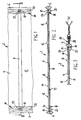
- a joint tape 2 consists of an extruded profile strand 4 made of an elastic material, such as plastic or rubber (rubber).
- the profile strand 4 has a thickened edge bead 6 on each of its two longitudinal edges. These edge beads 6 cause an extension or interruption of the water circulation path to avoid water cross bridges.
- a positive connection between the joint tape 2 and the concrete enclosing it is also achieved by the edge beads 6.
- the joint tape 2 also has a plurality of strip-shaped stiffening elements 8 which run transversely to the longitudinal direction of the profile and are spaced apart from one another and preferably have a flat, rectangular cross section.
- the stiffening elements 8 can have a width of 5 to 8 mm and a thickness of 1 to 1.5 mm.
- the mutual distance of the stiffening elements 8 from one another is advantageously 10 to 15 cm.
- the stiffening elements 8 suitably consist of metal or a rigid plastic, for example hard PVC.
- the stiffening elements 8 serve to stiffen the joint tape 2 in the transverse direction in such a way that it can always be laid out flat.
- the stiffening elements 8 are now only partially embedded in the profile strand 4 in the area of their two ends 10. Im between the embedded Stiffening elements 8 advantageously lie essentially at the ends 10 of the area 10 of the profile strand 4. In the exemplary embodiment shown, the stiffening elements 8 lie directly on the surface 12 of the profile strand 4. However, it is also possible that the stiffening elements 8 are integrally connected to the profile strand 4 in this area or, due to the production of the joint tape 2 in the extrusion process, at least partially stick to the profile strand 4 superficially.
- the profile strand 4 has ribs 16 running in the longitudinal direction of the profile on its side 14 opposite the stiffening elements 8. These ribs 16 also serve to improve the sealing effect of the joint tape according to the invention and also for a positive connection between the joint tape 2 and the concrete.
- the stiffening elements 8 i.e. on the surface 12, on the other hand, there is no need for such ribs, since these would be bridged by the stiffening elements 8 anyway.
- the surface 12 can therefore be formed without profiling.
- the ends 10 of the stiffening elements 8 according to the invention are embedded in retaining ribs 18 formed on the surface 12 of the profile strand 4 and extending in the profile longitudinal direction.
- These holding ribs 18 are expediently formed in the transition area between one of the thickened edge beads 6 and the surface 12 of the profile strand 4.
- At least one further rib 20 is formed in each case in the region of the holding ribs 18.
- the embedded ends 10 of the stiffening elements 8 are also connected to the profile strand 4 in a material and / or form-fitting manner.
- the stiffening elements 8 each have at least one through hole 22 in their embedded ends 10 through which the material of the profile strand 4 or the holding ribs 18 extends in a form-fitting manner.
- form-fitting material through connections 24 are formed in the area of the through holes 8.
- a material connection can be provided in the area of the ends 10, for example via an adhesion promoter coating. It is also possible to vulcanize the stiffening elements 8 in the region of the ends 10 into the profile strand 4, which then consists of rubber.
- the profile strand 4 is connected to an edge strip 26 in the region of at least one longitudinal edge, ie in particular following the edge bead 6, this edge strip 26 having through holes 28 spaced apart from one another in the profile longitudinal direction.
- the joint tape 2 preferably has an edge strip 26 on both edges.
- This edge strip according to the invention is used to fix the joint tape 2 before concreting, by pulling a binding or string wire 30 through the eyelet-like through holes 28, whereby then the ends of the wire 30 are braced and fastened, for example, to a wooden casing.
- the edge strip 26 is cohesive, in particular homogeneous, i.e. Uniform material, is connected to the profile strand 4. It is particularly expedient here if the profile strand 4 is made of soft PVC and the edge strip 26 is made of hard PVC, since these materials can be homogeneously connected to one another, in particular during the extrusion process. This also ensures on the one hand a necessary elasticity of the joint tape 2 or the profile strand 4, but on the other hand also ensures sufficient strength of the edge strip 26, wherein tearing out of the through holes 28 by tensile forces applied via the wire 30 is advantageously almost impossible.
- the production of the joint tape 2 according to the invention is advantageously very simple and therefore inexpensive.
- the profile strand 4 and on the other hand the retaining ribs 18 are expediently extruded first, but then brought together in a common extruder or spray head, including the stiffening elements 8, and thus connected in a material-uniform, homogeneous manner by embedding the ends 10 of the stiffening elements 8.
- This allows continuous production, with the stiffening elements 8 being able to be fed automatically, in cycles.
Landscapes
- Engineering & Computer Science (AREA)
- Architecture (AREA)
- Physics & Mathematics (AREA)
- Electromagnetism (AREA)
- Civil Engineering (AREA)
- Structural Engineering (AREA)
- Building Environments (AREA)
- Cable Accessories (AREA)
- Adhesive Tapes (AREA)
- Bridges Or Land Bridges (AREA)
Priority Applications (1)
| Application Number | Priority Date | Filing Date | Title |
|---|---|---|---|
| AT90113993T ATE86333T1 (de) | 1989-07-25 | 1990-07-21 | Fugenband mit versteifungselementen. |
Applications Claiming Priority (2)
| Application Number | Priority Date | Filing Date | Title |
|---|---|---|---|
| DE3924498 | 1989-07-25 | ||
| DE3924498A DE3924498A1 (de) | 1989-07-25 | 1989-07-25 | Fugenband mit versteifungselementen |
Publications (2)
| Publication Number | Publication Date |
|---|---|
| EP0410328A1 true EP0410328A1 (fr) | 1991-01-30 |
| EP0410328B1 EP0410328B1 (fr) | 1993-03-03 |
Family
ID=6385731
Family Applications (1)
| Application Number | Title | Priority Date | Filing Date |
|---|---|---|---|
| EP90113993A Expired - Lifetime EP0410328B1 (fr) | 1989-07-25 | 1990-07-21 | Bande couvre-joint avec des éléments de raidissement |
Country Status (5)
| Country | Link |
|---|---|
| EP (1) | EP0410328B1 (fr) |
| AT (1) | ATE86333T1 (fr) |
| DE (2) | DE3924498A1 (fr) |
| DK (1) | DK0410328T3 (fr) |
| ES (1) | ES2040007T3 (fr) |
Cited By (1)
| Publication number | Priority date | Publication date | Assignee | Title |
|---|---|---|---|---|
| EP4438465A1 (fr) * | 2023-03-27 | 2024-10-02 | Airbus Operations GmbH | Joint d'étanchéité, agencement de surface de commande, aile d'aéronef et aéronef |
Families Citing this family (1)
| Publication number | Priority date | Publication date | Assignee | Title |
|---|---|---|---|---|
| LU88161A1 (de) * | 1992-08-19 | 1994-04-01 | Arbed | Dichtungsprofil fuer Spundbohlenschloesser |
Citations (5)
| Publication number | Priority date | Publication date | Assignee | Title |
|---|---|---|---|---|
| DE1910807A1 (de) * | 1969-03-04 | 1970-11-26 | Gruenau Gmbh Chem Fab | Fugenband |
| DE1658780A1 (de) * | 1967-10-17 | 1971-04-01 | Abdichtungstechnik Schlott & B | Geteiltes Bodenfugenprofil mit eingelegter Metallschiene |
| FR2169138A1 (fr) * | 1972-01-24 | 1973-09-07 | Faleij Karl | |
| US4497762A (en) * | 1982-03-15 | 1985-02-05 | Winfried Meister | Method and apparatus for the production of jointing bands with embedded reinforcing profiles which run at right angles to the longitudinal axis of the band |
| EP0304225A1 (fr) * | 1987-08-19 | 1989-02-22 | W.R. Grace Limited | Joint d'étanchéité |
-
1989
- 1989-07-25 DE DE3924498A patent/DE3924498A1/de not_active Withdrawn
-
1990
- 1990-07-21 ES ES199090113993T patent/ES2040007T3/es not_active Expired - Lifetime
- 1990-07-21 DE DE9090113993T patent/DE59000956D1/de not_active Expired - Lifetime
- 1990-07-21 EP EP90113993A patent/EP0410328B1/fr not_active Expired - Lifetime
- 1990-07-21 AT AT90113993T patent/ATE86333T1/de not_active IP Right Cessation
- 1990-07-21 DK DK90113993.1T patent/DK0410328T3/da active
Patent Citations (5)
| Publication number | Priority date | Publication date | Assignee | Title |
|---|---|---|---|---|
| DE1658780A1 (de) * | 1967-10-17 | 1971-04-01 | Abdichtungstechnik Schlott & B | Geteiltes Bodenfugenprofil mit eingelegter Metallschiene |
| DE1910807A1 (de) * | 1969-03-04 | 1970-11-26 | Gruenau Gmbh Chem Fab | Fugenband |
| FR2169138A1 (fr) * | 1972-01-24 | 1973-09-07 | Faleij Karl | |
| US4497762A (en) * | 1982-03-15 | 1985-02-05 | Winfried Meister | Method and apparatus for the production of jointing bands with embedded reinforcing profiles which run at right angles to the longitudinal axis of the band |
| EP0304225A1 (fr) * | 1987-08-19 | 1989-02-22 | W.R. Grace Limited | Joint d'étanchéité |
Cited By (1)
| Publication number | Priority date | Publication date | Assignee | Title |
|---|---|---|---|---|
| EP4438465A1 (fr) * | 2023-03-27 | 2024-10-02 | Airbus Operations GmbH | Joint d'étanchéité, agencement de surface de commande, aile d'aéronef et aéronef |
Also Published As
| Publication number | Publication date |
|---|---|
| DK0410328T3 (da) | 1993-04-05 |
| ATE86333T1 (de) | 1993-03-15 |
| EP0410328B1 (fr) | 1993-03-03 |
| ES2040007T3 (es) | 1993-10-01 |
| DE3924498A1 (de) | 1991-01-31 |
| DE59000956D1 (de) | 1993-04-08 |
Similar Documents
| Publication | Publication Date | Title |
|---|---|---|
| DE2437809B2 (de) | Siebboden sowie siebkoerper und rahmen hierfuer | |
| AT389689B (de) | Endloses gelaenderlaufband aus elastischem material | |
| DE2823815C2 (de) | Fenster, vorzugsweise für Kraftfahrzeuge | |
| EP0285925B2 (fr) | Profil d'étanchéité | |
| EP0180688B1 (fr) | Elément de bordure à face supérieure recouverte d'un revêtement élastique | |
| EP0410328B1 (fr) | Bande couvre-joint avec des éléments de raidissement | |
| WO2009049338A1 (fr) | Couverture de voie | |
| DE3204411C2 (fr) | ||
| EP0410347A1 (fr) | Bande couvre-joint avec des caractéristiques modifiées du point de vue installation | |
| DE3629865A1 (de) | Strangfoermiges dichtungsprofil | |
| EP0629262A1 (fr) | Joint profile d'etancheite pour segments tubulaires de tunnels, notamment pour elements mis en place par flottaison | |
| DE3018383A1 (de) | Schlauchschelle | |
| DE1755283A1 (de) | Vorrichtung mit einem biegsamen endlosen Antriebsband,insbesondere fuer Fahrzeuge und ortsfeste Anlagen | |
| EP0722052A1 (fr) | Courroie de transmission | |
| DE2706277A1 (de) | Siebboden | |
| DE1800353A1 (de) | Raupenband fuer Schneefahrzeuge | |
| DE3436201A1 (de) | Bauteil | |
| AT333830B (de) | Fahrbahnubergang zur uberbruckung von fahrbahnfugen | |
| EP0181607B1 (fr) | Dispositif pour la fixation des rails de chemin de fer sur des traverses en acier en forme d'Y | |
| DE3203022C2 (de) | Schienenverbindung für elektrische Spiel- und Modellbahnen | |
| DE29519544U1 (de) | Sollriß-Fugenschiene für Betonbauten | |
| DE1919138C3 (fr) | ||
| DE3309114A1 (de) | Putzprofilleiste | |
| DE2249970C3 (de) | Vorrichtung zum Überbrücken und Abdecken von Dehnungsfugen an Brücken und ähnlichen Bauwerken | |
| DE2759076C2 (fr) |
Legal Events
| Date | Code | Title | Description |
|---|---|---|---|
| PUAI | Public reference made under article 153(3) epc to a published international application that has entered the european phase |
Free format text: ORIGINAL CODE: 0009012 |
|
| 17P | Request for examination filed |
Effective date: 19901130 |
|
| AK | Designated contracting states |
Kind code of ref document: A1 Designated state(s): AT BE CH DE DK ES FR GB GR IT LI LU NL SE |
|
| 17Q | First examination report despatched |
Effective date: 19910926 |
|
| GRAA | (expected) grant |
Free format text: ORIGINAL CODE: 0009210 |
|
| AK | Designated contracting states |
Kind code of ref document: B1 Designated state(s): AT BE CH DE DK ES FR GB GR IT LI LU NL SE |
|
| PG25 | Lapsed in a contracting state [announced via postgrant information from national office to epo] |
Ref country code: GR Free format text: LAPSE BECAUSE OF FAILURE TO SUBMIT A TRANSLATION OF THE DESCRIPTION OR TO PAY THE FEE WITHIN THE PRESCRIBED TIME-LIMIT Effective date: 19930303 |
|
| REF | Corresponds to: |
Ref document number: 86333 Country of ref document: AT Date of ref document: 19930315 Kind code of ref document: T |
|
| ITF | It: translation for a ep patent filed | ||
| REG | Reference to a national code |
Ref country code: DK Ref legal event code: T3 |
|
| GBT | Gb: translation of ep patent filed (gb section 77(6)(a)/1977) |
Effective date: 19930304 |
|
| REF | Corresponds to: |
Ref document number: 59000956 Country of ref document: DE Date of ref document: 19930408 |
|
| ET | Fr: translation filed | ||
| REG | Reference to a national code |
Ref country code: ES Ref legal event code: FG2A Ref document number: 2040007 Country of ref document: ES Kind code of ref document: T3 |
|
| PLBE | No opposition filed within time limit |
Free format text: ORIGINAL CODE: 0009261 |
|
| STAA | Information on the status of an ep patent application or granted ep patent |
Free format text: STATUS: NO OPPOSITION FILED WITHIN TIME LIMIT |
|
| 26N | No opposition filed | ||
| EPTA | Lu: last paid annual fee | ||
| EAL | Se: european patent in force in sweden |
Ref document number: 90113993.1 |
|
| REG | Reference to a national code |
Ref country code: GB Ref legal event code: IF02 |
|
| REG | Reference to a national code |
Ref country code: CH Ref legal event code: PFA Owner name: FIRMA WINFRIED MEISTER Free format text: FIRMA WINFRIED MEISTER#ROSENTHALSTRASSE 14#WUPPERTAL 21 (DE) -TRANSFER TO- FIRMA WINFRIED MEISTER#ROSENTHALSTRASSE 14#WUPPERTAL 21 (DE) |
|
| PGFP | Annual fee paid to national office [announced via postgrant information from national office to epo] |
Ref country code: FR Payment date: 20090722 Year of fee payment: 20 Ref country code: DK Payment date: 20090729 Year of fee payment: 20 Ref country code: ES Payment date: 20090723 Year of fee payment: 20 |
|
| PGFP | Annual fee paid to national office [announced via postgrant information from national office to epo] |
Ref country code: SE Payment date: 20090729 Year of fee payment: 20 Ref country code: NL Payment date: 20090726 Year of fee payment: 20 Ref country code: LU Payment date: 20090728 Year of fee payment: 20 Ref country code: GB Payment date: 20090722 Year of fee payment: 20 Ref country code: CH Payment date: 20090727 Year of fee payment: 20 Ref country code: AT Payment date: 20090729 Year of fee payment: 20 |
|
| PGFP | Annual fee paid to national office [announced via postgrant information from national office to epo] |
Ref country code: DE Payment date: 20090925 Year of fee payment: 20 |
|
| PGFP | Annual fee paid to national office [announced via postgrant information from national office to epo] |
Ref country code: BE Payment date: 20090729 Year of fee payment: 20 |
|
| PGFP | Annual fee paid to national office [announced via postgrant information from national office to epo] |
Ref country code: IT Payment date: 20090727 Year of fee payment: 20 |
|
| REG | Reference to a national code |
Ref country code: NL Ref legal event code: V4 Effective date: 20100721 |
|
| REG | Reference to a national code |
Ref country code: CH Ref legal event code: PL |
|
| BE20 | Be: patent expired |
Owner name: FIRMA WINFRIED *MEISTER Effective date: 20100721 |
|
| REG | Reference to a national code |
Ref country code: DK Ref legal event code: EUP |
|
| REG | Reference to a national code |
Ref country code: GB Ref legal event code: PE20 Expiry date: 20100720 |
|
| REG | Reference to a national code |
Ref country code: ES Ref legal event code: FD2A Effective date: 20100722 |
|
| EUG | Se: european patent has lapsed | ||
| PG25 | Lapsed in a contracting state [announced via postgrant information from national office to epo] |
Ref country code: NL Free format text: LAPSE BECAUSE OF EXPIRATION OF PROTECTION Effective date: 20100721 Ref country code: ES Free format text: LAPSE BECAUSE OF EXPIRATION OF PROTECTION Effective date: 20100722 |
|
| PG25 | Lapsed in a contracting state [announced via postgrant information from national office to epo] |
Ref country code: GB Free format text: LAPSE BECAUSE OF EXPIRATION OF PROTECTION Effective date: 20100720 |
|
| PG25 | Lapsed in a contracting state [announced via postgrant information from national office to epo] |
Ref country code: DE Free format text: LAPSE BECAUSE OF EXPIRATION OF PROTECTION Effective date: 20100721 |