EP0410331A2 - Dynamische Auswuchtmaschine mit Torsionsschwingungen - Google Patents
Dynamische Auswuchtmaschine mit Torsionsschwingungen Download PDFInfo
- Publication number
- EP0410331A2 EP0410331A2 EP90114001A EP90114001A EP0410331A2 EP 0410331 A2 EP0410331 A2 EP 0410331A2 EP 90114001 A EP90114001 A EP 90114001A EP 90114001 A EP90114001 A EP 90114001A EP 0410331 A2 EP0410331 A2 EP 0410331A2
- Authority
- EP
- European Patent Office
- Prior art keywords
- vibration
- unbalance
- rotor
- specimen
- dynamic balancing
- Prior art date
- Legal status (The legal status is an assumption and is not a legal conclusion. Google has not performed a legal analysis and makes no representation as to the accuracy of the status listed.)
- Withdrawn
Links
- 230000005284 excitation Effects 0.000 description 50
- 238000010276 construction Methods 0.000 description 9
- 239000013598 vector Substances 0.000 description 8
- 230000006835 compression Effects 0.000 description 7
- 238000007906 compression Methods 0.000 description 7
- 238000005259 measurement Methods 0.000 description 6
- 238000007796 conventional method Methods 0.000 description 4
- 230000006870 function Effects 0.000 description 4
- 230000008878 coupling Effects 0.000 description 3
- 238000010168 coupling process Methods 0.000 description 3
- 238000005859 coupling reaction Methods 0.000 description 3
- 206010001497 Agitation Diseases 0.000 description 2
- 230000003321 amplification Effects 0.000 description 2
- 230000005540 biological transmission Effects 0.000 description 2
- 238000001514 detection method Methods 0.000 description 2
- 238000003199 nucleic acid amplification method Methods 0.000 description 2
- 238000012360 testing method Methods 0.000 description 2
- 238000004458 analytical method Methods 0.000 description 1
- 238000000429 assembly Methods 0.000 description 1
- 230000000712 assembly Effects 0.000 description 1
- 238000005452 bending Methods 0.000 description 1
- 230000007423 decrease Effects 0.000 description 1
- 238000010586 diagram Methods 0.000 description 1
- 230000000694 effects Effects 0.000 description 1
- 238000002474 experimental method Methods 0.000 description 1
- 238000000034 method Methods 0.000 description 1
- 230000010363 phase shift Effects 0.000 description 1
- QHGVXILFMXYDRS-UHFFFAOYSA-N pyraclofos Chemical compound C1=C(OP(=O)(OCC)SCCC)C=NN1C1=CC=C(Cl)C=C1 QHGVXILFMXYDRS-UHFFFAOYSA-N 0.000 description 1
Images



Classifications
-
- G—PHYSICS
- G01—MEASURING; TESTING
- G01M—TESTING STATIC OR DYNAMIC BALANCE OF MACHINES OR STRUCTURES; TESTING OF STRUCTURES OR APPARATUS, NOT OTHERWISE PROVIDED FOR
- G01M1/00—Testing static or dynamic balance of machines or structures
- G01M1/02—Details of balancing machines or devices
- G01M1/04—Adaptation of bearing support assemblies for receiving the body to be tested
-
- G—PHYSICS
- G01—MEASURING; TESTING
- G01M—TESTING STATIC OR DYNAMIC BALANCE OF MACHINES OR STRUCTURES; TESTING OF STRUCTURES OR APPARATUS, NOT OTHERWISE PROVIDED FOR
- G01M1/00—Testing static or dynamic balance of machines or structures
- G01M1/02—Details of balancing machines or devices
- G01M1/06—Adaptation of drive assemblies for receiving the body to be tested
-
- G—PHYSICS
- G01—MEASURING; TESTING
- G01M—TESTING STATIC OR DYNAMIC BALANCE OF MACHINES OR STRUCTURES; TESTING OF STRUCTURES OR APPARATUS, NOT OTHERWISE PROVIDED FOR
- G01M1/00—Testing static or dynamic balance of machines or structures
- G01M1/14—Determining imbalance
- G01M1/16—Determining imbalance by oscillating or rotating the body to be tested
- G01M1/22—Determining imbalance by oscillating or rotating the body to be tested and converting vibrations due to imbalance into electric variables
Definitions
- the present invention relates to a dynamic balancing machine, and more particularly to a dynamic balancing machine in which torsional excitation is utilized.
- rotor In order to measure the unbalance of an object to be examined for unbalance (hereinafter called a "rotor"), it is most common either to measure unbalance force caused by the revolution of the rotor or to measure vibration caused by the unbalance of the rotor during its revolution.
- the revolution speed of the rotor when the revolution speed of the rotor approaches a critical speed, vibration caused by unbalance becomes so violent that occasionally the rotor flies out of its supporting members.
- the rotor has to be revolved at a higher revolution speed than the primary critical speed.
- a flexible rotor revolved at such a high revolution speed is attended with a high accident frequency rate.
- the present invention is concerned with the application of this theory to a conventional dynamic balancing machine.
- the dynamic balancing machine in accordance with the present invention includes a means for holding a rotor in such a manner that the rotor is adapted to revolve and vibrate, a driving means for subjecting the rotor to torsional excitation within the limits of a prescribed angle of torsion, and a means for detecting unbalance vibration which occurs when the rotor is subjected to torsional excitation, the detection being effected at least in two angular positions in the direction of rotation of the rotor, a means for generating a reference signal every time the rotor has rotated by a very small prescribed angle, and a calculating means in which the amount and angular position of dynamic unbalance of the rotor is calculated on the basis of unbalance vibration detected in two angular positions by the means for detecting unbalance vibration on one hand and on the basis of the reference signal outputted from the means for generating a reference signal on the other hand.
- the means for detecting unbalance vibration can detect unbalance vibration in arbitrary angular positions which are away from each other by 90 o .
- the driving means fulfills another function as a means for revolving the rotor and includes a change-over means for making a switchover from the function as a means for revolving the rotor to the function as a means for subjecting the rotor to torsional excitation within the limits of a prescribed angle of torsion and vice versa.
- the change-over means is also capable of subjecting the rotor to torsional excitation while revolving the rotor.
- the driving means further includes an excitation frequency changer from which a desired excitation frequency can be taken, a memory in which angles of excitation are stored beforehand, and a servo output unit in which the output taken from the excitation frequency changer is made either into a sine wave or into a chopping wave on the basis of data supplied from the memory.
- the driving means further includes a rotating shaft for revolving the rotor, a first cam attached to the rotating shaft, a second cam attached to a journal of the rotor, and a connecting member by which the first cam is connected to the second cam in such a manner that the distance from the center of revolution of the first cam to the point at which one end of the connecting member is pivotally connected to the first cam is shorter than the distance from the center of revolution of the second cam to the point at which the other end of the connecting member is pivotally connected to the second cam.
- the driving means may further include a hydraulic motor.
- Unbalance vibration caused by torsional excitation occurs when the direction in which driving torque is exerted on the rotor is positively changed.
- Unbalance vibration detected by the means for detecting unbalance vibration has a direction perpendicular to an unbalance vector which would occur if the rotor were revolved.
- the amplitude of this unbalance vibration is proportional to the amount of unbalance. Therefore, if the unbalance vibration of a rotor is detected at least in two angular positions, this is tantamount to the detection of two components into which the unbalance of the rotor has been resolved.
- the two components of unbalance of the rotor are compounded, and the amount and angular position of the unbalance are calculated on the basis of the reference signal outputted from the means for generating a reference signal.
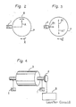
- a component A (Fig. 2) of unbalance exists in a balancing plane P.
- vibration B occurs in the direction perpendicular to the direction of the component A of unbalance.
- the vibration B can be detected by a pickup 1, which is angularly away by 90 o from the direction of the component A of unbalance.
- the vibration B1 caused by such torsional excitation occurs, e.g., in the positive direction (i.e., in the direction which allows the balancing plane P to recede from the pickup 1) and, when the balancing plane P is subjected to torsional excitation in a direction just as a left handed screw is threaded into a tapped hole, the vibration B1 caused by such torsional excitation occurs, e.g., in the negative direction (i.e., in the direction which allows the balancing plane P to come close to the pickup 1).
- the vibration B1 caused by such torsional excitation occurs, e.g., in the negative direction (i.e., in the direction which allows the balancing plane P to come close to the pickup 1).
- an encoder 4 is directly attached to a rotor 3 to be subjected to torsional excitation and is connected to a counter circuit 5.
- the construction of this circuit is such that pulse signals outputted from the encoder 4 cause the counter to read up when the rotor 3 is subjected to excitation in a direction just as a right handed screw is threaded into a tapped hole as viewed from the side of the encoder 4, and cause the counter to count down when the rotor 3 is subjected to excitation in the opposite direction.
- the point at which a zero output is taken from the pickup 1 is the angular position of unbalance measured by the pickup 1 as existing in the rotor 3.
- the following description is based on the assumption that the excitation frequency is lower than the resonance frequency of the rotor.
- the component A1 or A1′ of unbalance detected by the pickup 1 and assumed to have a direction perpendicular to the vibration B1 merely represents one of two component vectors into which an unbalance vector A o (Fig. 6) existing in the balancing plane P can be resolved. This is because the pickup 1 is not always disposed in an angular position which is exactly away from the unbalance vector A o by 90 o but is disposed in an arbitrary angular position.
- vibration B1 and B2 caused by torsional excitation are detected by means of pickups 1 and 2 disposed in arbitrary angular positions (which are preferably away from each other by 90 o ) as shown in Fig. 6. Then, components A1 and A2 of the unbalance, which correspond to the vibration B1 and B2 respectively, are found and combined vectorially with each other to yield the unbalance vector A o in the balancing plane P.
- the present invention can be applied to either of the horizontal and vertical type dynamic balancing machines.
- the rotor may be directly driven by a driving motor.
- driving torque developed by the driving motor may be transmitted to the rotor through a belt transmission.
- the means for holding a rotor may be capable of vibrating the rotor only in a single direction so as to allow the rotor to have only one degree of freedom.
- the means for holding a rotor may be capable of vibrating the rotor in two directions so as to allow the rotor to have two degrees of freedom.
- vibration has only to be detected in a single direction by means of at least one pickup.
- vibration has only to be detected in two directions by means of at least two pickups.
- a feature common to all cases where the present invention is applied to a known type of dynamic balancing machines is that a means, such as an encoder, for detecting the angle of rotation is attached to a journal of the rotor and that the driving motor is capable of subjecting the rotor to torsional excitation. Reference to the construction embodying this feature will be made later.
- Fig. 7 is a perspective view of a horizontal type dynamic balancing machine embodying the present invention.
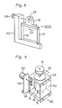
- Fig. 8 is a perspective view of a measuring stand used therein.
- the horizontal type dynamic balancing machine 10 includes two measuring stands 12 and 13 disposed on a machine base 11. Both ends of a rotor 14 are held by the measuring stands 12 and 13, and the measurement of unbalance can be carried out in two balancing planes of the rotor 14.
- the space between the measuring stands 12 and 13 is adjustable so as to adapt the measuring stands 12 and 13 for various rotors 14 different in length from each other.
- the adjustability of the space is attained if at least one of the measuring stands 12 and 13 is made movable along the machine base 11.
- the machine base 11 carries a mount 15 for a driving motor 16.
- the rotating shaft of the driving motor 16 is coupled with a journal of the rotor 14 through a joint 17.
- the direction in which the driving torque of the driving motor 16 is exerted on the rotor 14 is periodically changed so as to subject the rotor 14 to torsional excitation at a prescribed amplitude.
- An encoder 18 attached to the rotating shaft of the driving motor 16 generates a pulse every time the rotating shaft has rotated by a very small prescribed angle.
- the angle at which the rotor 14 has been subjected to torsional excitation is detected on the basis of the number of pulses generated by the encoder 18 and fed to an up-down counter.
- the measuring stands 12 and 13 are identical in construction. As shown in Fig. 8, each of them includes a bearing member 19 having a hole 25 for receiving a journal of the rotor 14, a pair of flat springs 21 holding the bearing member 19 in such a manner that the bearing member 19 is adapted to vibrate only in a single direction 20 so as to have only one degree of freedom, and a vibration pickup 24 mounted on a supporting member 23 and adapted to detect vibration when the bearing member 19 vibrates in the direction 20.
- Each journal of the rotor may be supported by a pair of rollers instead of being supported by the bearing member 19 having the hole 25.
- Fig. 9 is a perspective view of a vertical type dynamic balancing machine embodying the present invention.
- the vertical type dynamic balancing machine 30 includes a pair of flat springs 32 extending vertically from a machine base 31 and holding a vibrating frame 34, which is thereby adapted to vibrate only in a single direction 35 so as to have only one degree of freedom.
- the driving motor 16 is mounted on the undersurface of the vibrating frame 34. A portion of the rotating shaft of the driving motor 16 projects upwardly from the upper surface of the vibrating frame 34.
- the rotor 14 mounted on the above-mentioned portion of the rotating shaft is directly driven by the driving motor 16.
- the direction in which the driving torque of the driving motor 16 is exerted on the rotor 14 is periodically changed so as to subject the rotor 14 to torsional excitation at a prescribed amplitude.
- An encoder 18 attached to the lower portion of the rotating shaft of the driving motor 16 generates a pulse every time the rotating shaft has rotated by a very small prescribed angle.
- a vibration pickup 24 mounted on a supporting member 38 is adapted to detect vibration when the frame 34 vibrates.
- Fig. 10 is a schematic illustration to help explain the contruction of another horizontal type dynamic balancing machine embodying the present invention.
- the rotor 14 mounted on the horizontal type dynamic balancing machine 40 is not directly driven by the driving motor 16, but the driving torque of the driving motor 16 is transmitted to an intermediate shaft 43 through a belt 42.
- the rotor 14, which is coupled with the intermediate shaft 43 through a joint 44, is indirectly driven.
- the encoder 18 is attached to the intermediate shaft 43.
- Fig. 11 is a perspective view of another vertical type dynamic balancing machine embodying the present invention.
- the rotor 14 mounted on the vertical type dynamic balancing machine 45 is not directly driven by the driving motor 16, but the driving torque of the driving motor 16 is transmitted to a spindle unit 46 through a belt 48.
- the rotor 14 mounted on the spindle unit 46 is indirectly driven thereby.
- a pair of flat springs 49 hold the spindle unit 46, which is thereby adapted to vibrate only in a single direction 54 so as to have only one degree of freedom.
- the vibration of the spindle unit 46 is detected by the vibration pickup 24.
- the encoder 18 is attached to the spindle unit 46.
- Fig. 12 is a perspective view of a measuring stand used in another horizontal type dynamic balancing machine embodying the present invention.
- the measuring stand 60 which can take the place, e.g., of the measuring stands 12 and 13 shown in Fig. 7, includes a pair of flat springs 61 and another pair of flat springs 62. These two pairs of flat springs form a pair of doglegged spring assemblies, which hold the bearing member 19 in such a manner that the bearing member 19 is adapted to vibrate in two directions 20 and 65 so as to have two degrees of freedom. Vibration in the direction 20 is detected by a vibration pickup 24a, while vibration in the direction 65 is detected by a vibration pickup 24b.
- Fig. 13 is a view illustrating another example of a measuring stand which also allows the bearing member to have two degrees of freedom.
- the measuring stand 66 includes a pair of compression springs 68 and another pair of compression springs 69. These two pairs of compression springs 68 and 69 are angularly disposed away from each other so as to hold a bearing member 67 in such a manner that the bearing member 67 is adapted to vibrate in two directions 72 and 73 so as to have two degrees of freedom.
- the lower ends of the compression springs 68 and 69 are secured to base members 70 and 71 respectively. Vibration in the direction 72 is detected by a vibration pickup 24a disposed between the compression springs 68, while vibration in the direction 73 is detected by a vibration pickup 24b disposed between the compression springs 69.
- Fig. 14 is a perspective view of another vertical type dynamic balancing machine embodying the present invention.
- the vibrating frame and the intermediate frame of the vertical type dynamic balancing machine 75 are adapted to vibrate in their respective directions 76 and 77 so as to have two degrees of freedom altogether. Vibration in the direction 76 is detected by a vibration pickup 24a, while vibration in the direction 77 is detected by a vibration pickup 24b.
- a pair of flat springs 79 extend vertically from a machine base 78 and hold the intermediate frame 80, which is thereby adapted to vibrate in the direction 77.
- Another pair of flat springs 81 disposed perpendicularly to the flat springs 79 extend vertically from the intermediate frame 80 and hold the vibrating frame 82, which is thereby adapted to vibrate in the direction 76.
- the driving motor 16 is mounted on the undersurface of the vibrating frame 82.
- An encoder 18 is attached to the lower portion of the rotating shaft of the driving motor 16. A portion of the rotating shaft of the driving motor 16 projects upwardly from the upper surface of the vibrating frame 82.
- the rotor 14 is mounted on the above-mentioned portion of the rotating shaft so as to be subjected to torsional excitation by the driving motor 16.
- Fig. 15 is a perspective view of another vertical type dynamic balancing machine embodying the present invention.
- the vibrating frame of the vertical type dynamic balancing machine 85 is adapted to vibrate in two directions 86 and 87 so as to have two degrees of freedom.
- the vibrating frame 88 is substantially square with four corners supported by four compression springs 89 in such a manner that the vibrating frame 88 is adapted to vibrate.
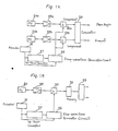
- Fig. 1A is a diagrammatic view of an unbalance measuring circuit for a dynamic balancing machine which allows the rotor to have two degrees of freedom
- Fig. 18 is a diagrammatic view of an unbalance measuring circuit for a dynamic balancing machine which allows the rotor to have only one degree of freedom.
- the output taken from the vibration pickup 24a is amplified in an amplification circuit 55a and fed to a multiplication circuit 56a.
- the output taken from the vibration pickup 24b is amplified in an amplification circuit 55b and fed to a multiplication circuit 56b.
- Output pulses generated by the encoder 18 are fed to an up-down counter 57.
- the encoder 18 is capable of producing the outputs with three phases. Outputs in phases A and B consist respectively of, e.g., 360 pulses per revolution. The encoder 18 is further capable of producing an output with phase Z, in which a pulse per revolution is outputted. Output pulses in phase A have a phase difference of 90 o to those in phase B. This phase difference gives a clue to the discrimination between RRC and RLC of the encoder 18.
- Output pulses from the encoder 18 cause the up-down counter 57 to read up or count down.
- the up-down counter 57 reads up in case of RRC of the encoder 18 and counts down in case of RLC of the encoder 18.
- the direction of rotation of the encoder 18 is detected on the basis of the phase difference between output pulses in phase A and those in phase B. Since the encoder 18 is alternately subjected to RRC and RLC, the number of pulses counted by the up-down counter 57 periodically increases and decreases to a maximum value and a minimum value respectively.
- the output taken from the up-down counter 57 is fed to a sine-wave generator circuit 58, in which a sine wave conforming closely to the excitation frequency of the rotor 14 is formed on the basis of the number of pulses counted by the up-down counter 57.
- the output taken from the sine-wave generator circuit 58 is fed to the multiplication circuits 56a and 56b, in which the outputs taken respectively from the vibration pickups 24a and 24b are multiplied by the sine wave formed in the sine-wave generator circuit 58.
- the outputs taken from the multiplication circuits 56a and 56b represent the components A1 and A2 (Fig. 6) of the unbalance respectively.
- the unbalance vector A o existing in the balancing plane is calculated from these two components, and two signals respectively representing the amount and angular position of unbalance are outputted.
- the unbalance measuring circuit for the dynamic balancing machine which allows the rotor to have only one degree of freedom has a substantially identical construction with the unbalance measuring circuit for the dynamic balancing machine which allows the rotor to have two degrees of freedom.
- the measurement of vibration by the use of a circuit designed for one degree of freedom makes it necessary to subject the rotor 14 to the first torsional excitation in a certain angular position, revolve the rotor 14 by a certain angle of rotation (by 90 o from an ideal viewpoint), and subject the rotor 14 to the second torsional excitation.
- the circuit shown in Fig. 18 is such that the output taken from the multiplication circuit 56 is temporarily stored in a memory circuit 39.
- circuits shown in Figs. 1A and 1B can not only be used in case where unbalance is measured on the basis of vibration caused by torsional excitation, but also be used in case where unbalance is measured by the conventional method, i.e., on the basis of vibration caused by the revolution of the rotor.
- the encoder 18 generates pulses in phase Z, which can be fed to the sine-wave generator circuit 58 so that a sine wave may be formed on the basis of these pulses.
- the output taken from the vibration pickup 24 (or 24a, 24b) is multiplied by the above-mentioned sine wave formed on the basis of pulses in phase Z.
- the product obtained from this multiplication allows the angular position of unbalance to be drawn therefrom.
- the rotor may be subjected to torsional excitation in addition to being revolved as is the case with the conventional method of a dynamic balance test.
- unbalance vibration is caused by revolution combined vectorially with torsional excitation.
- the amount and angular position of unbalance can be obtained from the analysis of this unbalance vibration.
- Fig. 16 is a diagrammatic view of a control circuit for periodically changing the direction in which the driving torque of the driving motor 16 is exerted on the rotor.
- the driving motor 16 is driven by a driver unit 91, which in turn is under the control of a servo unit 92.
- Angles such as ⁇ 1 o , ⁇ 2 o and ⁇ 3 o , at which the rotor is to be subjected to torsional excitation, are stored in a memory 93 and are ready for being supplied to the servo unit 92.
- the servo unit 92 On receipt of an instruction about an excitation frequency, the servo unit 92 controls the driver unit 91 on the basis of the excitation frequency.
- the memory 93 On receipt of an instruction about an angle at which the rotor is to be subjected to torsional excitation, the memory 93 recalls a pertinent one of the pieces of information stored therein and supplies it to the servo unit 92.
- the servo unit 92 sinusoidally changes its output voltage with the lapse of time t as shown in Fig. 17.
- the driver unit 91 excites the driving motor 16 in such a manner that the driving torque of the driving motor 16 changes in accordance with a sinusoidal change in the output voltage of the servo unit 92.
- this output voltage may take the form of a chopping wave or a saw-tooth wave instead of taking the form of a sine wave.
- the encoder 18 is connected to the driving motor 16. Output pulses generated by the encoder 18 are fed back to the driver unit 91 and the servo unit 92 so that excitation may be effected by the driving motor 16 at a prescribed frequency and amplitude.
- a means for driving the rotor 14 for the concomitant purpose of subjecting it to torsional excitation may be of such construction as shown in Fig. 18, in which the driving motor 16 may be an AC motor, DC motor or hydraulic motor.
- the driving torque of the driving motor 16 is transmitted to an intermediate shaft 100, with which the rotor 14 is coupled.
- the transmission of driving torque is effected through a transmitting means, which includes a first cam disk 101 fixedly connected to the rotating shaft of the driving motor 16, a second cam disk 102 fixedly connected to the intermediate shaft 100, and a coupling rod 103 by which the first cam disk is connected to the second cam disk in such a manner that she distance from the center of revolution of the first cam disk 101 to the point at which one end of the coupling rod 103 is pivotally connected to the first cam disk 101 is shorter than the distance from the center of revolution of the second cam disk 102 to the point at which the other end of the coupling rod 103 is pivotally connected to the second cam disk 102.
- the shapes of the first and second cam disks 101 and 102 may be varied or altered.
Landscapes
- Physics & Mathematics (AREA)
- General Physics & Mathematics (AREA)
- Testing Of Balance (AREA)
Applications Claiming Priority (2)
| Application Number | Priority Date | Filing Date | Title |
|---|---|---|---|
| JP197372/89 | 1989-07-28 | ||
| JP1197372A JP2892383B2 (ja) | 1989-07-28 | 1989-07-28 | ねじり加振を利用した動釣合い試験機 |
Publications (2)
| Publication Number | Publication Date |
|---|---|
| EP0410331A2 true EP0410331A2 (de) | 1991-01-30 |
| EP0410331A3 EP0410331A3 (en) | 1992-07-01 |
Family
ID=16373407
Family Applications (1)
| Application Number | Title | Priority Date | Filing Date |
|---|---|---|---|
| EP19900114001 Withdrawn EP0410331A3 (en) | 1989-07-28 | 1990-07-21 | Dynamic balancing machine utilizing torsional vibration |
Country Status (2)
| Country | Link |
|---|---|
| EP (1) | EP0410331A3 (de) |
| JP (1) | JP2892383B2 (de) |
Cited By (4)
| Publication number | Priority date | Publication date | Assignee | Title |
|---|---|---|---|---|
| EP0629847A3 (de) * | 1993-06-18 | 1995-02-22 | Lucas Automation & Control | Unwuchtmessvorrichtung und -verfahren. |
| EP1936347A3 (de) * | 2006-12-18 | 2010-01-13 | Schenck RoTec GmbH | Vorrichtung zur Lagerung von Rotoren, insbesondere Gelenkwellen, in einer Auswuchtmaschine |
| EP2428788A1 (de) | 2010-09-09 | 2012-03-14 | Hofmann Maschinen- und Anlagenbau GmbH | Vorrichtung zur Drehlagerung eines auszuwuchtenden Rotors |
| US20240192048A1 (en) * | 2022-12-09 | 2024-06-13 | Abb Schweiz Ag | Method and An Arrangement for Identification of Lateral Vibration Characteristics of An Electric Machine |
Families Citing this family (3)
| Publication number | Priority date | Publication date | Assignee | Title |
|---|---|---|---|---|
| CN100387958C (zh) * | 2004-07-13 | 2008-05-14 | 浙江大学 | 动平衡测量仪 |
| JP5897835B2 (ja) * | 2011-07-21 | 2016-03-30 | 株式会社テクノオーミ | 計測装置 |
| JP6371668B2 (ja) * | 2014-10-21 | 2018-08-08 | Nok株式会社 | 回転アンバランス測定装置 |
Family Cites Families (2)
| Publication number | Priority date | Publication date | Assignee | Title |
|---|---|---|---|---|
| FR1305632A (fr) * | 1960-09-13 | 1962-10-05 | Schenck Gmbh Carl | Procédé d'équilibrage dynamique et machine utilisable pour sa mise en oeuvre |
| US4283957A (en) * | 1979-06-25 | 1981-08-18 | Zonic Corporation | Torsional exciter for a rotating structure |
-
1989
- 1989-07-28 JP JP1197372A patent/JP2892383B2/ja not_active Expired - Fee Related
-
1990
- 1990-07-21 EP EP19900114001 patent/EP0410331A3/en not_active Withdrawn
Cited By (8)
| Publication number | Priority date | Publication date | Assignee | Title |
|---|---|---|---|---|
| EP0629847A3 (de) * | 1993-06-18 | 1995-02-22 | Lucas Automation & Control | Unwuchtmessvorrichtung und -verfahren. |
| EP1936347A3 (de) * | 2006-12-18 | 2010-01-13 | Schenck RoTec GmbH | Vorrichtung zur Lagerung von Rotoren, insbesondere Gelenkwellen, in einer Auswuchtmaschine |
| CN101231206B (zh) * | 2006-12-18 | 2010-12-15 | 申克罗泰克有限责任公司 | 支承平衡机中的转子,尤其万向轴的装置 |
| US7946172B2 (en) | 2006-12-18 | 2011-05-24 | Schenck Rotec Gmbh | Device for mounting rotors, in particular articulated shafts, in a balancing machine |
| EP2428788A1 (de) | 2010-09-09 | 2012-03-14 | Hofmann Maschinen- und Anlagenbau GmbH | Vorrichtung zur Drehlagerung eines auszuwuchtenden Rotors |
| DE102010044849A1 (de) | 2010-09-09 | 2012-03-15 | Hofmann Maschinen- Und Anlagenbau Gmbh | Vorrichtung zur Drehlagerung eines auszuwuchtenden Rotors |
| US8875572B2 (en) | 2010-09-09 | 2014-11-04 | Hofmann Maschinen-Und Anlagenbau Gmbh | Apparatus for rotatably mounting a rotor to be balanced |
| US20240192048A1 (en) * | 2022-12-09 | 2024-06-13 | Abb Schweiz Ag | Method and An Arrangement for Identification of Lateral Vibration Characteristics of An Electric Machine |
Also Published As
| Publication number | Publication date |
|---|---|
| EP0410331A3 (en) | 1992-07-01 |
| JP2892383B2 (ja) | 1999-05-17 |
| JPH0359432A (ja) | 1991-03-14 |
Similar Documents
| Publication | Publication Date | Title |
|---|---|---|
| EP0740141B1 (de) | Rotierende elektromagnetische Vibration für rotierenden Körper und Dämpfer unter Verwendung des betreffenden rotierenden Körpers | |
| EP0410331A2 (de) | Dynamische Auswuchtmaschine mit Torsionsschwingungen | |
| JPS59100839A (ja) | 遠心分離機のドラムの固体負荷を測定する方法と測定装置 | |
| US3922922A (en) | Device for balancing unbalanced rotors in which the rotor can swing between horizontal and vertical positions | |
| US5033302A (en) | Rotary balancing machine mounting assembly with integral calibration device | |
| JP3083242B2 (ja) | 回転体の静止場での振動評価方法 | |
| US3090237A (en) | Lathe balancing support stands | |
| KR100905397B1 (ko) | 주기적 회전진동을 이용한 동적 발란싱 장치 및 방법 | |
| US5691477A (en) | Torsional vibrator | |
| RU96121141A (ru) | Способ определения пространственной угловой ориентации подвижного объекта и лазерный измерительный блок | |
| JP4098429B2 (ja) | 釣合い試験機及び釣合い試験方法 | |
| RU2382999C1 (ru) | Способ динамической балансировки ротора | |
| RU2077035C1 (ru) | Способ динамической балансировки роторов и колебательная система балансировочного станка для его осуществления | |
| SU1144015A1 (ru) | Балансировочный станок | |
| RU2845170C1 (ru) | Способ динамического управления вектором вынуждающего усилия в вибромашинах на основе инерционных виброприводов и устройство для его реализации | |
| US6742400B2 (en) | Device and method for measuring cross-inertia-moment in limited angular rotary axis | |
| US3079801A (en) | Method and machine for determining unbalance of rotating workpieces | |
| SU1585821A1 (ru) | Лабораторна установка дл исследовани характеристик приводных устройств и нагрузочных механизмов | |
| JPS6147660B2 (de) | ||
| SU1728703A1 (ru) | Ротационный испытательный стенд | |
| JPH0572970B2 (de) | ||
| SU637755A1 (ru) | Способ определени динамических характеристик опор турбоагрегатов | |
| SU870453A1 (ru) | Способ управлени внутренними напр жени ми детали | |
| SU896434A1 (ru) | Устройство дл балансировки роторов | |
| RU1827555C (ru) | Способ динамических испытаний роторов |
Legal Events
| Date | Code | Title | Description |
|---|---|---|---|
| PUAI | Public reference made under article 153(3) epc to a published international application that has entered the european phase |
Free format text: ORIGINAL CODE: 0009012 |
|
| AK | Designated contracting states |
Kind code of ref document: A2 Designated state(s): DE FR GB |
|
| PUAL | Search report despatched |
Free format text: ORIGINAL CODE: 0009013 |
|
| AK | Designated contracting states |
Kind code of ref document: A3 Designated state(s): DE FR GB |
|
| STAA | Information on the status of an ep patent application or granted ep patent |
Free format text: STATUS: THE APPLICATION IS DEEMED TO BE WITHDRAWN |
|
| 18D | Application deemed to be withdrawn |
Effective date: 19930105 |