EP0410441A2 - Verrouillage d'engrenage différentiel pour automobiles - Google Patents
Verrouillage d'engrenage différentiel pour automobiles Download PDFInfo
- Publication number
- EP0410441A2 EP0410441A2 EP90114323A EP90114323A EP0410441A2 EP 0410441 A2 EP0410441 A2 EP 0410441A2 EP 90114323 A EP90114323 A EP 90114323A EP 90114323 A EP90114323 A EP 90114323A EP 0410441 A2 EP0410441 A2 EP 0410441A2
- Authority
- EP
- European Patent Office
- Prior art keywords
- differential
- lock
- differential lock
- shafts
- control unit
- Prior art date
- Legal status (The legal status is an assumption and is not a legal conclusion. Google has not performed a legal analysis and makes no representation as to the accuracy of the status listed.)
- Granted
Links
- 238000001514 detection method Methods 0.000 claims abstract description 3
- 230000008878 coupling Effects 0.000 claims description 8
- 238000010168 coupling process Methods 0.000 claims description 8
- 238000005859 coupling reaction Methods 0.000 claims description 8
- 230000005540 biological transmission Effects 0.000 description 2
- 210000000078 claw Anatomy 0.000 description 2
- 238000010276 construction Methods 0.000 description 1
- 238000010586 diagram Methods 0.000 description 1
- 238000002347 injection Methods 0.000 description 1
- 239000007924 injection Substances 0.000 description 1
- 238000005259 measurement Methods 0.000 description 1
- 230000035939 shock Effects 0.000 description 1
Images

Classifications
-
- B—PERFORMING OPERATIONS; TRANSPORTING
- B60—VEHICLES IN GENERAL
- B60K—ARRANGEMENT OR MOUNTING OF PROPULSION UNITS OR OF TRANSMISSIONS IN VEHICLES; ARRANGEMENT OR MOUNTING OF PLURAL DIVERSE PRIME-MOVERS IN VEHICLES; AUXILIARY DRIVES FOR VEHICLES; INSTRUMENTATION OR DASHBOARDS FOR VEHICLES; ARRANGEMENTS IN CONNECTION WITH COOLING, AIR INTAKE, GAS EXHAUST OR FUEL SUPPLY OF PROPULSION UNITS IN VEHICLES
- B60K17/00—Arrangement or mounting of transmissions in vehicles
- B60K17/34—Arrangement or mounting of transmissions in vehicles for driving both front and rear wheels, e.g. four wheel drive vehicles
- B60K17/344—Arrangement or mounting of transmissions in vehicles for driving both front and rear wheels, e.g. four wheel drive vehicles having a transfer gear
- B60K17/346—Arrangement or mounting of transmissions in vehicles for driving both front and rear wheels, e.g. four wheel drive vehicles having a transfer gear the transfer gear being a differential gear
- B60K17/3462—Arrangement or mounting of transmissions in vehicles for driving both front and rear wheels, e.g. four wheel drive vehicles having a transfer gear the transfer gear being a differential gear with means for changing distribution of torque between front and rear wheels
-
- B—PERFORMING OPERATIONS; TRANSPORTING
- B60—VEHICLES IN GENERAL
- B60K—ARRANGEMENT OR MOUNTING OF PROPULSION UNITS OR OF TRANSMISSIONS IN VEHICLES; ARRANGEMENT OR MOUNTING OF PLURAL DIVERSE PRIME-MOVERS IN VEHICLES; AUXILIARY DRIVES FOR VEHICLES; INSTRUMENTATION OR DASHBOARDS FOR VEHICLES; ARRANGEMENTS IN CONNECTION WITH COOLING, AIR INTAKE, GAS EXHAUST OR FUEL SUPPLY OF PROPULSION UNITS IN VEHICLES
- B60K23/00—Arrangement or mounting of control devices for vehicle transmissions, or parts thereof, not otherwise provided for
- B60K23/08—Arrangement or mounting of control devices for vehicle transmissions, or parts thereof, not otherwise provided for for changing number of driven wheels, for switching from driving one axle to driving two or more axles
- B60K23/0808—Arrangement or mounting of control devices for vehicle transmissions, or parts thereof, not otherwise provided for for changing number of driven wheels, for switching from driving one axle to driving two or more axles for varying torque distribution between driven axles, e.g. by transfer clutch
Definitions
- the invention relates to a differential lock for motor vehicles, which can be actuated automatically, the differential having a drive shaft and two output shafts and an electronic control device is provided, the operating data of at least two of the shafts are entered.
- the lock or the clutch In order to recognize when the necessary adhesion of all wheels on the road is again given, the lock or the clutch must be opened again and again at comparatively short intervals in order to measure the respective speed differences of the wheels and, depending on them, to re-engage the lock or leave open.
- the invention is therefore based on the object to remedy these shortcomings and to provide a differential lock of the type described which can be engaged and disengaged independently without having to carry out a frequently recurring release of the clutch for the respective measurement of the wheel speed differences in the locked state.
- the invention solves this problem in that sensors for the current torque detection are attached to the shafts arranges and a torque limit value for switching on and the ratio of two torques for switching off the differential lock is stored in the control unit in the control lever position and the selected gear of the motor vehicle.
- the control unit compares that one of the measured torques reaches or falls below the associated torque limit value despite the actuation of the foot pedal and considering the selected transmission gear when the drive clutch is closed, the control unit delivers a signal to the actuating device of the differential lock, which is naturally present, and the lock with Switched on with the help of the actuator.
- the control unit continuously compares the entered measured torques or the torque calculated from them with the system-specific release condition for the differential lock, which release condition by the ratio of two torques is defined in their size. Once equality has been achieved, the control unit sends a pulse to the actuating device of the differential lock in the release direction.
- the differential lock is in a known manner as a positive Coupling designed and determined in particular for a differential gear of a transfer case, the control unit then delivers a pulse for changing the torque in the drive train or in a drive train of the differential gear when reaching the torque ratio to switch off the differential lock.
- the differential lock Since the differential lock is designed as a positive coupling, a complete locking effect is achieved despite the comparatively small dimensions. Nevertheless, there are no difficulties in disengaging the lock due to any tension, because the control unit provides, in addition to the impulse to the actuating device of the differential lock or the clutch, another pulse for changing the torque in the drive train or in a drive train of the differential, and thereby any tension between the interlocking coupling elements.
- the impulse for changing the torque can consist in that one of the drive and output lines is braked briefly or the drive line is briefly accelerated, which is hardly noticeable during driving.
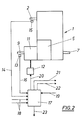
- a transfer case 1 arranged between the front and rear axles of an all-wheel drive motor vehicle, wherein the transmission drive shaft 2 is connected to the motor of the motor vehicle via the drive clutch, not shown.
- the drive shaft 2 drives the planet gear carrier 4 of a differential gear, designated 5 overall, via an intermediate gear 3.
- the ring gear 6 of this differential 5 is non-rotatably connected to the output shaft 7 leading to the rear axle, whereas the sun gear 8 drives the output shaft 9 leading to the front axle.
- the sliding sleeve 10 of a claw coupling 11 is rotatably mounted, by means of which the planet carrier 4 and the output shaft 9 can be rigidly coupled, so that this clutch 11 results in a differential lock.
- a device 12 which is only indicated schematically and which works, for example, with compressed air against spring force, serves to move the sleeve 10, that is to say to actuate the coupling 11, that is to say to engage and release the differential lock.
- a force measuring pin 13 is mounted as an axis for the corresponding planet gear, the values supplied by the force measuring pin 13 being transmitted inductively into the line 16, so that the torque of the output shaft 9 is continuously detected.
- a suitable sensor 15 (FIG. 2) is also provided for the torque occurring on the drive shaft 2.
- the torque values detected by the sensor 15 and by the force measuring bolt 13, which also acts as a sensor, are input via lines 14 and 16 to a control unit 17 which also receives signals via lines 18 as to whether the differential lock 11 is in the disengaged or engaged state. Furthermore, the electronic control can be switched to manual actuation of the differential lock 11 via the line 19.
- a line 20 leads from the control unit 17 to the actuating device 12 of the differential lock 11 and a further line 21 for controlling the brake of a vehicle wheel in order to enable the lock to be released by a short load change. Instead of or together with the control of the brake, the control rod of the injection pump of the motor vehicle engine could also be adjusted via line 22.
- the line 23 leads to a display device in order to make it clear to the driver whether the differential lock 11 is engaged or not.
Landscapes
- Engineering & Computer Science (AREA)
- Chemical & Material Sciences (AREA)
- Combustion & Propulsion (AREA)
- Transportation (AREA)
- Mechanical Engineering (AREA)
- Retarders (AREA)
- Arrangement And Mounting Of Devices That Control Transmission Of Motive Force (AREA)
Applications Claiming Priority (2)
| Application Number | Priority Date | Filing Date | Title |
|---|---|---|---|
| AT182389A AT398056B (de) | 1989-07-28 | 1989-07-28 | Ausgleichgetriebesperre für kraftfahrzeuge |
| AT1823/89 | 1989-07-28 |
Publications (3)
| Publication Number | Publication Date |
|---|---|
| EP0410441A2 true EP0410441A2 (fr) | 1991-01-30 |
| EP0410441A3 EP0410441A3 (en) | 1991-04-03 |
| EP0410441B1 EP0410441B1 (fr) | 1993-05-26 |
Family
ID=3521765
Family Applications (1)
| Application Number | Title | Priority Date | Filing Date |
|---|---|---|---|
| EP19900114323 Expired - Lifetime EP0410441B1 (fr) | 1989-07-28 | 1990-07-26 | Verrouillage d'engrenage différentiel pour automobiles |
Country Status (4)
| Country | Link |
|---|---|
| EP (1) | EP0410441B1 (fr) |
| AT (1) | AT398056B (fr) |
| DE (1) | DE59001541D1 (fr) |
| ES (1) | ES2040533T3 (fr) |
Cited By (7)
| Publication number | Priority date | Publication date | Assignee | Title |
|---|---|---|---|---|
| EP0510457A1 (fr) * | 1991-04-22 | 1992-10-28 | Steyr-Daimler-Puch Aktiengesellschaft | Accouplement à liaison de forme pour la boîte de transfert et le différentiel d'un véhicule à moteur, boîte de transfert et différentiel pourvus dudit accouplement, et sa méthode d'operation |
| EP0521275A1 (fr) * | 1991-06-29 | 1993-01-07 | Jean Walterscheid Gesellschaft mit beschränkter Haftung | Procédé et dispositif pour la mise en oeuvre d'un procédé de commande d'enclenchement et de désenclenchement de la propulsion des quatre roues d'un véhicule, en particulier d'un tracteur |
| EP0563619A1 (fr) * | 1992-04-01 | 1993-10-06 | Robert Bosch Gmbh | Véhicule tracteur |
| EP1253040A2 (fr) | 2001-04-25 | 2002-10-30 | ZF FRIEDRICHSHAFEN Aktiengesellschaft | Procédé et dispositif pour le blocage du différentiel dans des véhicules à toutes roues motrices |
| DE102004037196A1 (de) * | 2004-07-30 | 2006-03-23 | Zf Friedrichshafen Ag | Verfahren zur automatischen Betätigung von Längssperren bei allradgetriebenen Fahrzeugen, insbesondere bei Arbeitsmaschinen und Einsatzfahrzeugen |
| DE102011109340A1 (de) * | 2011-08-03 | 2013-02-07 | Daimler Ag | Verfahren zum Ausrücken einer Formschlusskupplung in einem Kraftfahrzeugantriebsstrang |
| DE102019217322A1 (de) * | 2019-11-08 | 2021-05-12 | Zf Friedrichshafen Ag | Verfahren zum Betreiben eines Antriebsstrangs mit wenigstens einem Differenzial |
Family Cites Families (9)
| Publication number | Priority date | Publication date | Assignee | Title |
|---|---|---|---|---|
| JPS56101443A (en) * | 1980-01-16 | 1981-08-14 | Fuji Heavy Ind Ltd | Differential restricting device |
| DE3313823A1 (de) * | 1983-04-16 | 1984-10-18 | Faun-Werke Kommunalfahrzeuge und Lastkraftwagen Karl Schmidt, 8500 Nürnberg | Antrieb fuer ein kraftfahrzeug, insbesondere ein nutzfahrzeug, mit wenigstens einem sperrdifferential |
| DE3425691A1 (de) * | 1984-07-12 | 1986-01-23 | Klöckner-Humboldt-Deutz AG, 5000 Köln | Vorrichtung zum form- oder kraftschluessigen einschalten einer differentialsperre |
| US4702341A (en) * | 1985-12-13 | 1987-10-27 | Toyota Jidosha Kabushiki Kaisha | Four wheel drive vehicle slippage control device and method limiting center differential action according to input torque supplied thereto |
| US4805721A (en) * | 1986-02-26 | 1989-02-21 | Fuji Jukogyo Kabushiki Kaisha | Power transmitting system for a four-wheel drive vehicle |
| US4805472A (en) * | 1986-09-30 | 1989-02-21 | Aisin Seiki Kabushiki Kaisha | Rotary torque transmission apparatus for four-wheel drive vehicles |
| DE3636260A1 (de) * | 1986-10-24 | 1988-05-05 | Opel Adam Ag | Kraftfahrzeug mit zumindest einer permanent angetriebenen achse sowie einer antriebsmaessig zuschaltbaren achse |
| JPH0788141B2 (ja) * | 1986-10-24 | 1995-09-27 | トヨタ自動車株式会社 | 差動制御装置 |
| JPS63203422A (ja) * | 1987-02-19 | 1988-08-23 | Fuji Heavy Ind Ltd | 4輪駆動装置 |
-
1989
- 1989-07-28 AT AT182389A patent/AT398056B/de not_active IP Right Cessation
-
1990
- 1990-07-26 ES ES90114323T patent/ES2040533T3/es not_active Expired - Lifetime
- 1990-07-26 DE DE9090114323T patent/DE59001541D1/de not_active Expired - Fee Related
- 1990-07-26 EP EP19900114323 patent/EP0410441B1/fr not_active Expired - Lifetime
Cited By (9)
| Publication number | Priority date | Publication date | Assignee | Title |
|---|---|---|---|---|
| EP0510457A1 (fr) * | 1991-04-22 | 1992-10-28 | Steyr-Daimler-Puch Aktiengesellschaft | Accouplement à liaison de forme pour la boîte de transfert et le différentiel d'un véhicule à moteur, boîte de transfert et différentiel pourvus dudit accouplement, et sa méthode d'operation |
| EP0521275A1 (fr) * | 1991-06-29 | 1993-01-07 | Jean Walterscheid Gesellschaft mit beschränkter Haftung | Procédé et dispositif pour la mise en oeuvre d'un procédé de commande d'enclenchement et de désenclenchement de la propulsion des quatre roues d'un véhicule, en particulier d'un tracteur |
| EP0563619A1 (fr) * | 1992-04-01 | 1993-10-06 | Robert Bosch Gmbh | Véhicule tracteur |
| EP1253040A2 (fr) | 2001-04-25 | 2002-10-30 | ZF FRIEDRICHSHAFEN Aktiengesellschaft | Procédé et dispositif pour le blocage du différentiel dans des véhicules à toutes roues motrices |
| DE10120221A1 (de) * | 2001-04-25 | 2003-01-02 | Zahnradfabrik Friedrichshafen | Verfahren und Einrichtung zur automatischen Betätigung von Differentialsperren bei allradgetriebenen Fahrzeugen |
| DE102004037196A1 (de) * | 2004-07-30 | 2006-03-23 | Zf Friedrichshafen Ag | Verfahren zur automatischen Betätigung von Längssperren bei allradgetriebenen Fahrzeugen, insbesondere bei Arbeitsmaschinen und Einsatzfahrzeugen |
| US7613559B2 (en) | 2004-07-30 | 2009-11-03 | Zf Friedrichshafen Ag | Method for automatically actuating longitudinal blocks in four wheel drive vehicles, in particular in working machines and service vehicles |
| DE102011109340A1 (de) * | 2011-08-03 | 2013-02-07 | Daimler Ag | Verfahren zum Ausrücken einer Formschlusskupplung in einem Kraftfahrzeugantriebsstrang |
| DE102019217322A1 (de) * | 2019-11-08 | 2021-05-12 | Zf Friedrichshafen Ag | Verfahren zum Betreiben eines Antriebsstrangs mit wenigstens einem Differenzial |
Also Published As
| Publication number | Publication date |
|---|---|
| DE59001541D1 (de) | 1993-07-01 |
| EP0410441B1 (fr) | 1993-05-26 |
| AT398056B (de) | 1994-09-26 |
| ATA182389A (de) | 1994-01-15 |
| ES2040533T3 (es) | 1993-10-16 |
| EP0410441A3 (en) | 1991-04-03 |
Similar Documents
| Publication | Publication Date | Title |
|---|---|---|
| DE3643831C2 (fr) | ||
| EP0128477B1 (fr) | Système de contrôle pour bloquer le différentiel | |
| DE102011056820B4 (de) | Antriebsstrang für ein Kraftfahrzeug | |
| DE3313823A1 (de) | Antrieb fuer ein kraftfahrzeug, insbesondere ein nutzfahrzeug, mit wenigstens einem sperrdifferential | |
| DE3703234C2 (fr) | ||
| DE19709419A1 (de) | Kraftfahrzeug und ein Verfahren zum Betrieb desselben | |
| DE2623138A1 (de) | Achsantrieb, insbesondere fuer kraftfahrzeuge | |
| DE102020114933B4 (de) | Betätigungsaktuator für eine Parksperre sowie Parksperre, Parksperrenvorrichtung, Getriebe und Antriebsstrang mit einem solchen | |
| DE4025697A1 (de) | Lenkeinrichtung | |
| DE19850977B4 (de) | Verfahren zum Prüfen einer automatisierten Kupplungseinrichtung | |
| WO2000075536A1 (fr) | Procede pour faire fonctionner une unite d'actionnement d'une boite de vitesse automatisee | |
| DE10051589A1 (de) | Betätigungsvorrichtung für eine Kupplungsvorrichtung | |
| EP0410441B1 (fr) | Verrouillage d'engrenage différentiel pour automobiles | |
| DE69000431T2 (de) | Gestaenge zur kraftuebertragung fuer kraftfahrzeuge. | |
| EP1556242B1 (fr) | Systeme d'entrainement pour un vehicule utilitaire tout-terrain | |
| DE1034988B (de) | Schleppzugantrieb | |
| EP0168775B1 (fr) | Dispositif pour l'enclenchement, soit par forme, soit par force, d'un verrouillage de différentiel | |
| DE3902082A1 (de) | Fahrzeug mit einer vorder- und einer hinterachse | |
| DE102017117079A1 (de) | Kraftfahrzeug-Immobilisierungsverfahren und Doppelkupplungsgetriebe | |
| DE3334721C2 (de) | Voll- oder teilautomatische Gangschaltung | |
| EP0424932B1 (fr) | Boîte de transfert pour véhicule | |
| DE102020205026A1 (de) | Schaltvorrichtung für einen Fahrzeuganhänger, Fahrzeuganhänger mit einer derartigen Schaltvorrichtung sowie Verfahren zum Schalten eines Getriebes eines Fahrzeuganhängers | |
| AT395566B (de) | Kraftfahrzeug mit einem mehrstufigen schaltgetriebe und zwei getriebenen achsen | |
| DE3536682A1 (de) | Vierrad-antriebsanordnung fuer fahrzeuge, insbesondere kraftfahrzeuge | |
| DE10120221A1 (de) | Verfahren und Einrichtung zur automatischen Betätigung von Differentialsperren bei allradgetriebenen Fahrzeugen |
Legal Events
| Date | Code | Title | Description |
|---|---|---|---|
| PUAI | Public reference made under article 153(3) epc to a published international application that has entered the european phase |
Free format text: ORIGINAL CODE: 0009012 |
|
| AK | Designated contracting states |
Kind code of ref document: A2 Designated state(s): DE ES FR GB IT NL SE |
|
| PUAL | Search report despatched |
Free format text: ORIGINAL CODE: 0009013 |
|
| RHK1 | Main classification (correction) |
Ipc: B60K 23/08 |
|
| AK | Designated contracting states |
Kind code of ref document: A3 Designated state(s): DE ES FR GB IT NL SE |
|
| 17P | Request for examination filed |
Effective date: 19910906 |
|
| 17Q | First examination report despatched |
Effective date: 19920708 |
|
| GRAA | (expected) grant |
Free format text: ORIGINAL CODE: 0009210 |
|
| ITF | It: translation for a ep patent filed | ||
| AK | Designated contracting states |
Kind code of ref document: B1 Designated state(s): DE ES FR GB IT NL SE |
|
| REF | Corresponds to: |
Ref document number: 59001541 Country of ref document: DE Date of ref document: 19930701 |
|
| GBT | Gb: translation of ep patent filed (gb section 77(6)(a)/1977) |
Effective date: 19930608 |
|
| ET | Fr: translation filed | ||
| REG | Reference to a national code |
Ref country code: ES Ref legal event code: FG2A Ref document number: 2040533 Country of ref document: ES Kind code of ref document: T3 |
|
| PLBE | No opposition filed within time limit |
Free format text: ORIGINAL CODE: 0009261 |
|
| STAA | Information on the status of an ep patent application or granted ep patent |
Free format text: STATUS: NO OPPOSITION FILED WITHIN TIME LIMIT |
|
| 26N | No opposition filed | ||
| PGFP | Annual fee paid to national office [announced via postgrant information from national office to epo] |
Ref country code: GB Payment date: 19940613 Year of fee payment: 5 |
|
| PGFP | Annual fee paid to national office [announced via postgrant information from national office to epo] |
Ref country code: NL Payment date: 19940731 Year of fee payment: 5 |
|
| EAL | Se: european patent in force in sweden |
Ref document number: 90114323.0 |
|
| PG25 | Lapsed in a contracting state [announced via postgrant information from national office to epo] |
Ref country code: GB Effective date: 19950726 |
|
| PG25 | Lapsed in a contracting state [announced via postgrant information from national office to epo] |
Ref country code: NL Effective date: 19960201 |
|
| GBPC | Gb: european patent ceased through non-payment of renewal fee |
Effective date: 19950726 |
|
| NLV4 | Nl: lapsed or anulled due to non-payment of the annual fee |
Effective date: 19960201 |
|
| REG | Reference to a national code |
Ref country code: FR Ref legal event code: TP |
|
| PGFP | Annual fee paid to national office [announced via postgrant information from national office to epo] |
Ref country code: FR Payment date: 20050708 Year of fee payment: 16 |
|
| PG25 | Lapsed in a contracting state [announced via postgrant information from national office to epo] |
Ref country code: IT Free format text: LAPSE BECAUSE OF NON-PAYMENT OF DUE FEES;WARNING: LAPSES OF ITALIAN PATENTS WITH EFFECTIVE DATE BEFORE 2007 MAY HAVE OCCURRED AT ANY TIME BEFORE 2007. THE CORRECT EFFECTIVE DATE MAY BE DIFFERENT FROM THE ONE RECORDED. Effective date: 20050726 |
|
| PGFP | Annual fee paid to national office [announced via postgrant information from national office to epo] |
Ref country code: ES Payment date: 20050818 Year of fee payment: 16 |
|
| REG | Reference to a national code |
Ref country code: FR Ref legal event code: ST Effective date: 20070330 |
|
| PGFP | Annual fee paid to national office [announced via postgrant information from national office to epo] |
Ref country code: DE Payment date: 20070719 Year of fee payment: 18 |
|
| REG | Reference to a national code |
Ref country code: ES Ref legal event code: FD2A Effective date: 20060727 |
|
| PG25 | Lapsed in a contracting state [announced via postgrant information from national office to epo] |
Ref country code: ES Free format text: LAPSE BECAUSE OF NON-PAYMENT OF DUE FEES Effective date: 20060727 |
|
| PGFP | Annual fee paid to national office [announced via postgrant information from national office to epo] |
Ref country code: SE Payment date: 20070704 Year of fee payment: 18 |
|
| PG25 | Lapsed in a contracting state [announced via postgrant information from national office to epo] |
Ref country code: FR Free format text: LAPSE BECAUSE OF NON-PAYMENT OF DUE FEES Effective date: 20060731 |
|
| EUG | Se: european patent has lapsed | ||
| PG25 | Lapsed in a contracting state [announced via postgrant information from national office to epo] |
Ref country code: DE Free format text: LAPSE BECAUSE OF NON-PAYMENT OF DUE FEES Effective date: 20090203 |
|
| PG25 | Lapsed in a contracting state [announced via postgrant information from national office to epo] |
Ref country code: SE Free format text: LAPSE BECAUSE OF NON-PAYMENT OF DUE FEES Effective date: 20080727 |