EP0410532A1 - Verfahren zum Synchronisieren durch Korrelation - Google Patents
Verfahren zum Synchronisieren durch Korrelation Download PDFInfo
- Publication number
- EP0410532A1 EP0410532A1 EP90202008A EP90202008A EP0410532A1 EP 0410532 A1 EP0410532 A1 EP 0410532A1 EP 90202008 A EP90202008 A EP 90202008A EP 90202008 A EP90202008 A EP 90202008A EP 0410532 A1 EP0410532 A1 EP 0410532A1
- Authority
- EP
- European Patent Office
- Prior art keywords
- synchronization
- correlation
- data
- correlations
- value
- Prior art date
- Legal status (The legal status is an assumption and is not a legal conclusion. Google has not performed a legal analysis and makes no representation as to the accuracy of the status listed.)
- Granted
Links
Images


Classifications
-
- H—ELECTRICITY
- H04—ELECTRIC COMMUNICATION TECHNIQUE
- H04L—TRANSMISSION OF DIGITAL INFORMATION, e.g. TELEGRAPHIC COMMUNICATION
- H04L27/00—Modulated-carrier systems
- H04L27/18—Phase-modulated carrier systems, i.e. using phase-shift keying
- H04L27/22—Demodulator circuits; Receiver circuits
- H04L27/227—Demodulator circuits; Receiver circuits using coherent demodulation
- H04L27/2271—Demodulator circuits; Receiver circuits using coherent demodulation wherein the carrier recovery circuit uses only the demodulated signals
-
- H—ELECTRICITY
- H04—ELECTRIC COMMUNICATION TECHNIQUE
- H04L—TRANSMISSION OF DIGITAL INFORMATION, e.g. TELEGRAPHIC COMMUNICATION
- H04L7/00—Arrangements for synchronising receiver with transmitter
- H04L7/04—Speed or phase control by synchronisation signals
- H04L7/041—Speed or phase control by synchronisation signals using special codes as synchronising signal
- H04L7/042—Detectors therefor, e.g. correlators, state machines
Definitions
- the present invention relates to a correlation synchronization method, a method involving a first step during which synchronization data representing a synchronization sequence is received, centered around a carrier frequency, from a second partial correlation step in which correlates the received data with parts of the locally generated synchronization sequence, a third step to provide an error indication on the carrier frequency received from the partial correlations and a fourth step to provide the usage with a peak correlation.
- the invention finds important applications especially in the field of data transmission by radio channel where the constraints are severe due to the strong disturbances to which these channels are subjected.
- French Patent No. 2,525,055 describes such a process which satisfies all the requirements as regards the precision of synchronization. However, it turned out that the computational load was too high for certain applications.
- the invention provides a method which involves fewer calculations so that when the implementation of the method is carried out by a microprocessor assembly, the latter can be assigned to additional tasks.
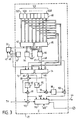
- the reference 1 indicates an antenna which receives data transmitted in the hf range, that is to say in a range ranging between 1 MHz and 30 MHz for example.
- the data used for synchronization are bivalent, a first value is represented by a 0 degree phase of a subcarrier at 1800 Hz and a second by a 180 degree phase of this same carrier. In other words, the data have values at the start: +1 and -1.
- the receiver shown in FIG. 1 supplies the output terminal 5 with data free, as far as possible, of these fluctuations and this interpenetration.
- FIG. 2 there is shown schematically a frame of received data. So the synchronization data are represented by an SQ sequence; after this sequence, the useful data DU. Only this DU data appears on terminal 5. In FIG. 7, a signal appears indicating that a sequence of synchronization data has been received.
- the reference 8 indicates the reception part of the receiver.
- An analog-digital converter 10 provides digital sub-samples at a rate N times faster than the data transmission. That is to say that for a transmitted data, there will be N subsamples. For the rest of the presentation, N will be taken equal to 4.
- a microprocessor assembly 12 performs processing on these samples to provide the information useful at terminals 5 and 7. For reasons of clarity, this assembly is shown in the form of a block diagram, but it is obvious to a person skilled in the art of transform this diagram into functional blocks interpretable by a microprocessor.
- the samples at the output of the converter 10 are first demolded at the nominal frequency of the subcarrier at 1800 Hz. For this, two multiplication members 14 and 15 are used followed by two low-pass filters 16 and 17 of so that when they are output, the transmitted data appears real and imaginary respectively, in baseband.
- the member 14 multiplies the samples by cos 2 ⁇ Ft and the member 15 by sin 2 ⁇ Ft where F is the frequency of the subcarrier.
- phase-shifting member 20 which phase-shifts it according to a quantity applied to its phase-shift control input 21.
- the samples, real part and imaginary part, at the output of the member 20 are systematically stored at the four successive positions (corresponding to the value N) of a buffer memory 22 with circular addressing.
- This memory can contain a hundred data. This memory will be read for the processing which will be described by a symbol number "ns" which defines the data and an index number "i" which defines the position of the subsample.
- sub-samples contained in this memory 22 can be selected selectively by an equalizer input member 25, on the one hand, and by a synchronization member 27, on the other hand.
- the output of member 25 is connected to the input of an equalizer 29 followed by a decision member 31 to supply the data to terminal 5.
- the synchronization unit 27 not only supplies the terminal 7 indicating the peak that a sequence of synchronization data has been received, as has been said, but also provides: - on an output 40, an index value, accompanied by the number, symbol to indicate the number of the sub-sample to be considered by the member 25, - on an output 42, another index value, accompanied by the symbol number for its own processing, and - On an output 44, a phase error to be used either by the member 25 via a switch 45, or by a filter 46. The output of this filter 46 is connected to the member 20 via a switch 47.
- This error phase represents the difference between the nominal value of the subcarrier and the value of the received subcarrier, this error can be due to Doppler effects or to frequency differences between the carriers.
- the equalizer input member 25 is formed of a phase shift member 50 followed by a normalization member 52 which centers the values of the data so that the equalization can be carried out under the best possible conditions.
- a mode is said to be the standby mode during which synchronization is obtained, which places the receiver in traffic mode. Both modes transmit useful data.
- Block 60 represents the sequence of data S (k) of the synchronization code SQ having for example 80 values this code is divided into 8 parts SQ1, SQ2, ..., SQ8 of 10 values each.
- the data received, taken from memory 22 by means of an addressing member 61 are correlated by means of a member represented by a block 62 to these different parts of blocks and according to one aspect of the invention, these correlations do not are performed only on parts SQ1 to SQ4.
- a selection member 64 determines among the correlations made for each of the four sub-samples and for each of these parts which gives the best result.
- f ( ⁇ ) K.exp (10. ⁇ ) where K is a constant. From this value of ⁇ we can derive a vector presenting a plurality of components V (k) by applying the value of ⁇ to a table 70 as shown in FIG. 4.
- V (k) exp (-j (k-1) ⁇ ) k ⁇ [1,80] The value ⁇ appears at output 67 and the vector at exit 68.
- Two blocks 72 and 74 perform a total correlation by operating on two halves of the SQ code.
- Each of these blocks comprises, as shown in FIG. 5, a phase shift member 80 followed by a correlation member 82 proper; the member 80 has its phase shift control connected to the output 68 to phase shift the data taken from the memory 22.
- this correlation will be carried out under good conditions since the frequency difference is already corrected.
- the correlations made by blocks 72 and 74 are respectively CORT (iopt, 1) and CORT (iopt, 2) given by The total CORTOTAL correlation performed on all the values S (k) of the synchronization code is given by the sum of the correlations executed by blocks 72 and 74.
- CORTOTAL CORT (iopt, 1) + CORT (iopt, 2) This sum is made by the adder 89.
- the following quantity is also evaluated using an element 95 to determine the combined value of CORT (iopt, 1) and a multiplier 96. [CORT5 (iopt, 1)] *. CORT (iopt, 2)
- This quantity gives, after treatment in an organ 98, a phase which added to that (output 67) previously calculated in block 66, by means of an adder 100 improves the latter in a significant manner.
- a final block 110 processes the information at the output of the element 91 and also that provided by a comparator 112 to take certain measures when a correlation peak has been determined by the member 112 which compares the value of the modulus of CORTOTAL with a TH threshold value previously established.
- One of these measures consists in defining the value "ns" for which synchronization has been detected.
- Another measurement consists in memorizing the phase value calculated at the output of the adder 100 and "iopt".
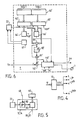
- the synchronization code is divided into two parts SQQ1 and SQQ2 in a block 60 ′.
- a block 62 ′ the correlations for all the indices "i" developed by the addressing member 61 ′ with the part of code SQQ1 are evaluated, a member 64 ′ determines, as in standby mode, the value "iopt" so that a block 65 ′ computes the correlation for this "iopt" of the data with the half-sequence SQQ2. From these two correlations, a phase error value is determined by means of a member 66 by taking the conjugate of the correlation given by 62 ′ and the correlation by 65 ′.
- the total correlation is calculated by adding those obtained by the organs 62 ′ and 66 ′.
- the square of the module is obtained, as in standby mode by means of elements 89 ′, 90 ′ and 91 ′ similar to elements 89, 90 and 91 described in FIG. 3.
- Synchronization is detected by the comparator 112 ′ and the final block 110 ′ has the same function as block 110.
- the phase error considered is only that provided by the member 66 ′ from the conjugate of the correlation provided by block 62 ′ and that of the block 65 ′.
- FIG. 7 it is shown how the switches 45 and 47 can be operated.
- the switch 47 When in standby, the switch 47 is put in a position such that the phase shift member 20 does not provide any phase correction, while the switch 45 is put in a position which allows the phase shift member 50 to already receive the first value found Ferr. Then in a following period, we are in traffic mode, the switches 45 and 47 are inverted so that the filtered phase error values Ferr, Ferr ′ are applied to the member 20 at each period and no more errors phase is not applied to the member 50. Thus, corrected data has been supplied to the equalizer 29.
Landscapes
- Engineering & Computer Science (AREA)
- Computer Networks & Wireless Communication (AREA)
- Signal Processing (AREA)
- Synchronisation In Digital Transmission Systems (AREA)
- Radio Transmission System (AREA)
Applications Claiming Priority (2)
| Application Number | Priority Date | Filing Date | Title |
|---|---|---|---|
| FR8910188A FR2650456A1 (fr) | 1989-07-28 | 1989-07-28 | Procede de synchronisation par correlation |
| FR8910188 | 1989-07-28 |
Publications (2)
| Publication Number | Publication Date |
|---|---|
| EP0410532A1 true EP0410532A1 (de) | 1991-01-30 |
| EP0410532B1 EP0410532B1 (de) | 1995-03-29 |
Family
ID=9384236
Family Applications (1)
| Application Number | Title | Priority Date | Filing Date |
|---|---|---|---|
| EP90202008A Expired - Lifetime EP0410532B1 (de) | 1989-07-28 | 1990-07-23 | Verfahren zum Synchronisieren durch Korrelation |
Country Status (7)
| Country | Link |
|---|---|
| US (1) | US5090028A (de) |
| EP (1) | EP0410532B1 (de) |
| JP (1) | JPH0370231A (de) |
| CA (1) | CA2021974A1 (de) |
| DE (1) | DE69018149D1 (de) |
| FI (1) | FI903726A7 (de) |
| FR (1) | FR2650456A1 (de) |
Cited By (3)
| Publication number | Priority date | Publication date | Assignee | Title |
|---|---|---|---|---|
| EP0711049A1 (de) * | 1994-11-07 | 1996-05-08 | Alcatel Telspace | Verfahren zur Referenzsymboldetektion in einem Emfängen für Digitaldaten |
| EP0734136A1 (de) * | 1995-03-22 | 1996-09-25 | Sagem Sa | Verfahren zur Übertragung digitaler Daten und Empfänger zur Durchführung des Verfahrens |
| SG85064A1 (en) * | 1992-05-29 | 2001-12-19 | Motorola Inc | Data communication receiver having burst error protected data synchronization |
Families Citing this family (20)
| Publication number | Priority date | Publication date | Assignee | Title |
|---|---|---|---|---|
| SE469678B (sv) * | 1992-01-13 | 1993-08-16 | Ericsson Telefon Ab L M | Saett foer synkronisering och kanalestimering i tdma- radiosystem |
| US6226336B1 (en) * | 1998-02-20 | 2001-05-01 | Telefonaktiebolaget Lm Ericsson (Publ) | Method and apparatus for detecting a frequency synchronization signal |
| US6421371B1 (en) * | 1998-11-17 | 2002-07-16 | Ericsson Inc. | Modulation sequence synchronization methods and apparatus employing partial sequence correlation |
| GB2347831B (en) * | 1999-03-06 | 2004-07-07 | Nec Technologies | Sychronisation in digital data transmission systems |
| US9020756B2 (en) * | 1999-04-23 | 2015-04-28 | Global Locate, Inc. | Method and apparatus for processing satellite positioning system signals |
| US6606346B2 (en) * | 2001-05-18 | 2003-08-12 | Global Locate, Inc. | Method and apparatus for computing signal correlation |
| US6704348B2 (en) | 2001-05-18 | 2004-03-09 | Global Locate, Inc. | Method and apparatus for computing signal correlation at multiple resolutions |
| DE19953350A1 (de) * | 1999-11-05 | 2001-05-23 | Infineon Technologies Ag | Vorrichtung zur Feinsynchronisation von Codesignalen |
| US6891880B2 (en) * | 2001-05-18 | 2005-05-10 | Global Locate, Inc. | Method and apparatus for performing signal correlation |
| US6819707B2 (en) | 2001-05-18 | 2004-11-16 | Global Locate, Inc. | Method and apparatus for performing signal correlation using historical correlation data |
| US7995682B2 (en) * | 2001-05-18 | 2011-08-09 | Broadcom Corporation | Method and apparatus for performing signal processing using historical correlation data |
| US7006556B2 (en) * | 2001-05-18 | 2006-02-28 | Global Locate, Inc. | Method and apparatus for performing signal correlation at multiple resolutions to mitigate multipath interference |
| US7190712B2 (en) * | 2001-05-18 | 2007-03-13 | Global Locate, Inc | Method and apparatus for performing signal correlation |
| US7567636B2 (en) | 2001-05-18 | 2009-07-28 | Global Locate, Inc. | Method and apparatus for performing signal correlation using historical correlation data |
| US7769076B2 (en) * | 2001-05-18 | 2010-08-03 | Broadcom Corporation | Method and apparatus for performing frequency synchronization |
| US8098716B2 (en) * | 2001-05-18 | 2012-01-17 | Broadcom Corporation | Method and apparatus for providing an energy-based signal tracking loop |
| US7064466B2 (en) * | 2001-11-27 | 2006-06-20 | Denso Corporation | Brushless rotary electric machine having tandem rotary cores |
| SG108874A1 (en) * | 2002-09-17 | 2005-02-28 | Sony Corp | Channel equalisation |
| DE102004059958B4 (de) * | 2004-12-13 | 2007-10-04 | Fraunhofer-Gesellschaft zur Förderung der angewandten Forschung e.V. | Vorrichtung und Verfahren zum Bestimmen eines Korrelationswertes |
| DE102004059957A1 (de) * | 2004-12-13 | 2006-06-14 | Fraunhofer-Gesellschaft zur Förderung der angewandten Forschung e.V. | Synchronisationsvorrichtung und Vorrichtung zum Erzeugen eines Synchronisationssignals |
Citations (2)
| Publication number | Priority date | Publication date | Assignee | Title |
|---|---|---|---|---|
| US4238739A (en) * | 1979-02-26 | 1980-12-09 | E-Systems, Inc. | Preset network for a phase lock loop |
| EP0091167A1 (de) * | 1982-04-09 | 1983-10-12 | Telecommunications Radioelectriques Et Telephoniques T.R.T. | Verfahren zur Frequenzkorrektur des lokalen Trägers im Empfänger eines Datenübertragungssystems und Empfänger unter Verwendung dieses Verfahrens |
Family Cites Families (7)
| Publication number | Priority date | Publication date | Assignee | Title |
|---|---|---|---|---|
| US4203071A (en) * | 1978-08-08 | 1980-05-13 | The Charles Stark Draper Laboratory, Inc. | Pseudo-random-number-code-detection and tracking system |
| US4485477A (en) * | 1982-07-19 | 1984-11-27 | Rca Corporation | Fast frequency/code search |
| US4621365A (en) * | 1984-11-16 | 1986-11-04 | Hughes Aircraft Company | Synchronization preamble correlation detector and frequency estimator |
| US4649543A (en) * | 1985-08-30 | 1987-03-10 | Motorola, Inc. | Synchronization sequence decoder for a digital radiotelephone system |
| GB2206267B (en) * | 1987-06-24 | 1991-09-25 | Plessey Co Plc | Novel correlator for synchronisation detection |
| US4847869A (en) * | 1987-12-04 | 1989-07-11 | Motorla, Inc. | Rapid reference acquisition and phase error compensation for radio transmission of data |
| US4829543A (en) * | 1987-12-04 | 1989-05-09 | Motorola, Inc. | Phase-coherent TDMA quadrature receiver for multipath fading channels |
-
1989
- 1989-07-28 FR FR8910188A patent/FR2650456A1/fr active Granted
-
1990
- 1990-07-23 DE DE69018149T patent/DE69018149D1/de not_active Expired - Lifetime
- 1990-07-23 EP EP90202008A patent/EP0410532B1/de not_active Expired - Lifetime
- 1990-07-25 JP JP2197566A patent/JPH0370231A/ja active Pending
- 1990-07-25 CA CA002021974A patent/CA2021974A1/en not_active Abandoned
- 1990-07-25 FI FI903726A patent/FI903726A7/fi not_active IP Right Cessation
- 1990-07-27 US US07/558,715 patent/US5090028A/en not_active Expired - Fee Related
Patent Citations (2)
| Publication number | Priority date | Publication date | Assignee | Title |
|---|---|---|---|---|
| US4238739A (en) * | 1979-02-26 | 1980-12-09 | E-Systems, Inc. | Preset network for a phase lock loop |
| EP0091167A1 (de) * | 1982-04-09 | 1983-10-12 | Telecommunications Radioelectriques Et Telephoniques T.R.T. | Verfahren zur Frequenzkorrektur des lokalen Trägers im Empfänger eines Datenübertragungssystems und Empfänger unter Verwendung dieses Verfahrens |
Cited By (6)
| Publication number | Priority date | Publication date | Assignee | Title |
|---|---|---|---|---|
| SG85064A1 (en) * | 1992-05-29 | 2001-12-19 | Motorola Inc | Data communication receiver having burst error protected data synchronization |
| EP0711049A1 (de) * | 1994-11-07 | 1996-05-08 | Alcatel Telspace | Verfahren zur Referenzsymboldetektion in einem Emfängen für Digitaldaten |
| FR2726711A1 (fr) * | 1994-11-07 | 1996-05-10 | Alcatel Telspace | Procede de detection de symboles de reference pour recepteur de donnees numeriques |
| US5732114A (en) * | 1994-11-07 | 1998-03-24 | Alcatel Telspace | Method of detecting reference symbols for a digital data receiver |
| EP0734136A1 (de) * | 1995-03-22 | 1996-09-25 | Sagem Sa | Verfahren zur Übertragung digitaler Daten und Empfänger zur Durchführung des Verfahrens |
| FR2732176A1 (fr) * | 1995-03-22 | 1996-09-27 | Sagem | Procede de transmission de donnees numeriques et recepteur pour la mise en oeuvre du procede |
Also Published As
| Publication number | Publication date |
|---|---|
| US5090028A (en) | 1992-02-18 |
| DE69018149D1 (de) | 1995-05-04 |
| FR2650456B1 (de) | 1994-07-13 |
| CA2021974A1 (en) | 1991-01-29 |
| FI903726A0 (fi) | 1990-07-25 |
| JPH0370231A (ja) | 1991-03-26 |
| EP0410532B1 (de) | 1995-03-29 |
| FR2650456A1 (fr) | 1991-02-01 |
| FI903726A7 (fi) | 1991-01-29 |
Similar Documents
| Publication | Publication Date | Title |
|---|---|---|
| EP0410532B1 (de) | Verfahren zum Synchronisieren durch Korrelation | |
| CA2187122C (fr) | Recepteur large bande a mesure de distance par signaux de code pseudo-aleatoire | |
| EP0091167B1 (de) | Verfahren zur Frequenzkorrektur des lokalen Trägers im Empfänger eines Datenübertragungssystems und Empfänger unter Verwendung dieses Verfahrens | |
| EP0451232B1 (de) | Kodeerfassungsverfahren und schaltung für spreizspektrumsignalempfänger | |
| FR2550030A1 (fr) | Procede et dispositif pour la demodulation de la modulation de frequence | |
| FR2739938A1 (fr) | Recepteur de determination d'une position a partir de reseaux de satellites | |
| EP0291979A1 (de) | Verfahren zur Demodulation von digital modulierten Signalen und Vorrichtung zur Durchführung des Verfahrens | |
| FR2770700A1 (fr) | Dispositif et procede pour synchroniser des oscillateurs dans un systeme de communication de donnees | |
| EP0004822A1 (de) | Verfahren und Anordnung zur Demodulation eines in Differenzphasenumtastung dargestellten Signals | |
| CA2412136A1 (fr) | Procede et dispositif de calcul de la fonction discriminante de signaux modules avec une ou plusieurs sous-porteuse | |
| FR2479629A1 (fr) | Procede de demodulation d'un signal module en amplitude, demodulateur mettant en oeuvre ce procede et systeme de television comportant un tel dispositif | |
| EP2095150B1 (de) | Verfahren und vorrichtung zum empfangen eines boc-modulierten funknavigationssignals | |
| EP0029376B1 (de) | Verfahren zur Demodulation eines frequenzmodulierten Signals und Demodulator zur Durchführung des Verfahrens | |
| EP3116182B1 (de) | Quadratur-demodulator für rfid-empfänger mit sehr hohem durchsatz | |
| EP0059138B1 (de) | Verfahren zur Radio-Lokalisierung mittels Bestimmung von Phasen elektromagnetischer Wellen und Empfängergerät zum Durchführen des Verfahrens | |
| EP0080544A1 (de) | Verfahren zum Empfangen eines Datensignals mit Doppelseitenbandmodulation und Quadraturträgern | |
| EP0061377B1 (de) | Digitaler Signaldemodulator und einen derartigen Demodulator enthaltender Farbfernsehempfänger oder -system | |
| EP0737868B1 (de) | Verzögerungsregelschleife für GPS Empfänger | |
| EP0097754A1 (de) | Tondetektor und Mehrfrequenzempfänger mit diesem Detektor | |
| FR3044104B1 (fr) | Recepteur pour systeme de positionnement par satellites et procede de traitement de signaux satellites | |
| EP1142147B1 (de) | Verfahren zum empfangen von spreizspektrumsignalen mit korrektur des frequenzversatzes | |
| EP4165441A2 (de) | Empfänger von funknavigationssignalen mit einem rechner eines korrelationsleistungsindikators | |
| EP0831626B1 (de) | Verfahren und Vorrichtung zum Ermitteln eines Trägerfrequenz-Fehlers | |
| FR2816142A1 (fr) | Procede et appareil d'identification d'un groupe de codes et de synchronisation pour un systeme ds-cdma | |
| EP0201946A1 (de) | Anordnung zur Messung des Geschwindigkeitsverlaufs einer Fläche |
Legal Events
| Date | Code | Title | Description |
|---|---|---|---|
| PUAI | Public reference made under article 153(3) epc to a published international application that has entered the european phase |
Free format text: ORIGINAL CODE: 0009012 |
|
| AK | Designated contracting states |
Kind code of ref document: A1 Designated state(s): DE FR GB IT SE |
|
| 17P | Request for examination filed |
Effective date: 19910725 |
|
| 17Q | First examination report despatched |
Effective date: 19930907 |
|
| GRAA | (expected) grant |
Free format text: ORIGINAL CODE: 0009210 |
|
| AK | Designated contracting states |
Kind code of ref document: B1 Designated state(s): DE FR GB IT SE |
|
| PG25 | Lapsed in a contracting state [announced via postgrant information from national office to epo] |
Ref country code: IT Free format text: LAPSE BECAUSE OF FAILURE TO SUBMIT A TRANSLATION OF THE DESCRIPTION OR TO PAY THE FEE WITHIN THE PRE;WARNING: LAPSES OF ITALIAN PATENTS WITH EFFECTIVE DATE BEFORE 2007 MAY HAVE OCCURRED AT ANY TIME BEFORE 2007. THE CORRECT EFFECTIVE DATE MAY BE DIFFERENT FROM THE ONE RECORDED.SCRIBED TIME-LIMIT Effective date: 19950329 Ref country code: GB Effective date: 19950329 |
|
| REF | Corresponds to: |
Ref document number: 69018149 Country of ref document: DE Date of ref document: 19950504 |
|
| PG25 | Lapsed in a contracting state [announced via postgrant information from national office to epo] |
Ref country code: SE Effective date: 19950629 |
|
| PG25 | Lapsed in a contracting state [announced via postgrant information from national office to epo] |
Ref country code: DE Effective date: 19950630 |
|
| PGFP | Annual fee paid to national office [announced via postgrant information from national office to epo] |
Ref country code: FR Payment date: 19950725 Year of fee payment: 6 |
|
| GBV | Gb: ep patent (uk) treated as always having been void in accordance with gb section 77(7)/1977 [no translation filed] |
Effective date: 19950329 |
|
| PLBE | No opposition filed within time limit |
Free format text: ORIGINAL CODE: 0009261 |
|
| STAA | Information on the status of an ep patent application or granted ep patent |
Free format text: STATUS: NO OPPOSITION FILED WITHIN TIME LIMIT |
|
| 26N | No opposition filed | ||
| PG25 | Lapsed in a contracting state [announced via postgrant information from national office to epo] |
Ref country code: FR Effective date: 19970328 |
|
| REG | Reference to a national code |
Ref country code: FR Ref legal event code: ST |