EP0410640A2 - Konfigurierbare Tastatur - Google Patents
Konfigurierbare Tastatur Download PDFInfo
- Publication number
- EP0410640A2 EP0410640A2 EP90307872A EP90307872A EP0410640A2 EP 0410640 A2 EP0410640 A2 EP 0410640A2 EP 90307872 A EP90307872 A EP 90307872A EP 90307872 A EP90307872 A EP 90307872A EP 0410640 A2 EP0410640 A2 EP 0410640A2
- Authority
- EP
- European Patent Office
- Prior art keywords
- key
- keyboard according
- display
- illumination
- keyboard
- Prior art date
- Legal status (The legal status is an assumption and is not a legal conclusion. Google has not performed a legal analysis and makes no representation as to the accuracy of the status listed.)
- Granted
Links
Images




Classifications
-
- H—ELECTRICITY
- H01—ELECTRIC ELEMENTS
- H01H—ELECTRIC SWITCHES; RELAYS; SELECTORS; EMERGENCY PROTECTIVE DEVICES
- H01H13/00—Switches having rectilinearly-movable operating part or parts adapted for pushing or pulling in one direction only, e.g. push-button switch
- H01H13/70—Switches having rectilinearly-movable operating part or parts adapted for pushing or pulling in one direction only, e.g. push-button switch having a plurality of operating members associated with different sets of contacts, e.g. keyboard
-
- G—PHYSICS
- G06—COMPUTING OR CALCULATING; COUNTING
- G06F—ELECTRIC DIGITAL DATA PROCESSING
- G06F3/00—Input arrangements for transferring data to be processed into a form capable of being handled by the computer; Output arrangements for transferring data from processing unit to output unit, e.g. interface arrangements
- G06F3/01—Input arrangements or combined input and output arrangements for interaction between user and computer
- G06F3/02—Input arrangements using manually operated switches, e.g. using keyboards or dials
- G06F3/023—Arrangements for converting discrete items of information into a coded form, e.g. arrangements for interpreting keyboard generated codes as alphanumeric codes, operand codes or instruction codes
- G06F3/0238—Programmable keyboards
-
- H—ELECTRICITY
- H01—ELECTRIC ELEMENTS
- H01H—ELECTRIC SWITCHES; RELAYS; SELECTORS; EMERGENCY PROTECTIVE DEVICES
- H01H2219/00—Legends
- H01H2219/002—Legends replaceable; adaptable
-
- H—ELECTRICITY
- H01—ELECTRIC ELEMENTS
- H01H—ELECTRIC SWITCHES; RELAYS; SELECTORS; EMERGENCY PROTECTIVE DEVICES
- H01H2219/00—Legends
- H01H2219/054—Optical elements
- H01H2219/06—Reflector
-
- H—ELECTRICITY
- H01—ELECTRIC ELEMENTS
- H01H—ELECTRIC SWITCHES; RELAYS; SELECTORS; EMERGENCY PROTECTIVE DEVICES
- H01H2221/00—Actuators
- H01H2221/07—Actuators transparent
-
- Y—GENERAL TAGGING OF NEW TECHNOLOGICAL DEVELOPMENTS; GENERAL TAGGING OF CROSS-SECTIONAL TECHNOLOGIES SPANNING OVER SEVERAL SECTIONS OF THE IPC; TECHNICAL SUBJECTS COVERED BY FORMER USPC CROSS-REFERENCE ART COLLECTIONS [XRACs] AND DIGESTS
- Y10—TECHNICAL SUBJECTS COVERED BY FORMER USPC
- Y10S—TECHNICAL SUBJECTS COVERED BY FORMER USPC CROSS-REFERENCE ART COLLECTIONS [XRACs] AND DIGESTS
- Y10S200/00—Electricity: circuit makers and breakers
- Y10S200/47—Light guides for switch indicators, e.g. prisms, reflectors or cables
Definitions
- the present invention relates to keyboards generally and more particularly to selectably configurable keyboards.
- U.S. Patent 4,431,988 describes a microprocessor-based keyboard/display unit for configuring control instruments which incorporates a configurable keyboard but does not provide means for indicating the key definitions on the keyboard.
- each key comprises a microchip device and one or more liquid crystal displays to indicate the programmed function of the key.
- U.S. Patent 4,385,366 describes a configurable keyboard wherein the key definition appears on a display below a transparent key and is viewed therethrough.
- U.S. Patent 4,333,090 illustrates a similar structure.
- U.S. Patent 4,633,227 describes a programmable keyboard for a typewriter or similar article wherein the key definition is displayed at a window location adjacent each key.
- the display information is provided by mechanically movable symbol bearing strips or by LCD displays located below the key definition display locations. This structure provides a very small key definition display.
- U.S. Patent 4,481,508 describes a programmable keyboard wherein the functions of the keys are displayed in a dot matrix display disposed thereabove.
- U.S. Patent 4,441,001 describes a keyboard for inputting plural letters or symbols which is similar to that described in U.S. Patent 4,633,227.
- the present invention seeks to provide an improved configurable keyboard which is relatively simple and of low cost.
- a keyboard comprising a plurality of key operated switches, each including a key having a manually engagable key surface, means for connecting the key operated switches to key operated utilization apparatus, means for selectably determining the function produced by operation of each of the key operated switches, and display means for displaying on each key its current function, as determined by the means for selectably determining, the means for displaying including means for providing a sensible output indication corresponding to the current function of each key at a location alongside each key.
- each of the keys includes means for redirecting light received from the sensible output indication to impinge on the manually engagable key surface, for providing a display of the current function of that key.
- the display of the current function of a key is formed on the manually engagable key surface.
- the manually engagable key surface comprises a transparent surface or a translucent surface.
- the keyboard also comprises at least one illumination source.
- the display means also comprises magnifying or reducing lens means.
- the display means comprises a double sided mirror disposed within each key or a plurality of mirrors.
- the double sided mirror includes a first reflecting surface and the means for providing a sensible output indication includes a selectably configurable mask associated with each key, the double sided mirror being operative to reflect illumination from a source of illumination located below the key and to direct the illumination to an adjacent key via a selectably configurable mask which displays the current function of the adjacent key.
- the double sided mirror includes a second reflecting surface and the means for providing a sensible output indication includes a selectably configurable mask associated with each key, the second reflecting surface being arranged to receive illumination via a selectably configurable mask disposed adjacent thereto and to direct the illumination onto a manually engagable surface for display thereat of the current function of the corresponding key.
- the selectably configurable mask comprises a liquid crystal display.
- the display means also comprises lens means having optical power.
- the output indication of each key is viewed through the manually engageable key surface.
- the means for redirecting light comprises reflecting surfaces having optical power.
- the display means comprises an upwardly facing reflecting surface disposed interiorly of each of the keys.
- the keyboard also comprises at least one downwardly facing reflecting surface disposed within each key.
- the upwardly facing reflecting surface and the downwardly facing reflecting surface are the two sides of a double sided mirror.
- the means for providing a sensible output indication comprises a selectably configurable mask and/or a replaceable template.
- the downwardly facing reflecting surfaces are operative to reflect illumination from a source of illumination located below the key and to direct the illumination to adjacent keys via a selectably configurable mask which displays the current function of the adjacent keys.
- the upwardly facing reflecting surface is arranged to receive illumination via a selectably configurable mask disposed adjacent thereto and to direct the illumination onto a manually engageable surface for display thereat of the current function of the corresponding key.
- the purpose of the present invention is to provide an economical and ergonometric multi-use keyboard, wherein the symbol associated with each key during each given mode of operation is displayed on the key and is readily seen by the operator.
- Figs. 1A and 1B illustrate a keyboard constructed and operative in accordance with a preferred embodiment of the present invention.
- the keyboard typically comprises a standard conventional keyboard 10, such as a commercially available keyboard for an IBM PC computer having modifications as described hereinbelow.
- the array 12 is interposed adjacent horizontal rows of symbol keys 16 in symbol display relationship therewith.
- An additional array 18 of display strips 20 may also be interposed adjacent vertical columns of function keys 22 in function display relationship therewith.
- the display strips provide a selectable optical mask, which defines an optical image when light is caused to pass therethrough.
- the display strips 14 and 20 may comprise cardboard or plastic templates bearing the symbols corresponding to each key.
- the symbols corresponding to each key may be changed by manually replacing the arrays 12 and 18 of display strips 14 and 20.
- the display strips could be replaced simultaneously with replacement of the font ball.
- the display strips could be replaced simultaneously with replacement of the daisy-wheel of the printer.
- the keys 16 and 22 are modified to provide a desired light path there through as will be described hereinbelow with reference to Figs. 2A - 6.
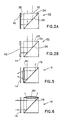
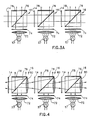
- Figs. 2A and 2B illustrate two alternative key function indication arrangements constructed and operative in accordance with a preferred embodiment of the present invention.
- ambient light is received through the top face 30 of a generally transparent key 32 and is reflected by the top facing reflecting surface 34 of a diagonally disposed mirror 36 disposed in key 32, through the key and via a portion 38 of a display strip, which is associated with a reflective surface 40.
- key 32 may comprise a prism.
- Mirror 36 is a mirror in the broad sense of the word, namely a generally light reflective surface, such as a polished plastic surface.
- the light is reflected by the reflective surface via portion 38 of the display strip, back through the key 32 and off surface 34 to the eye of an operator, thereby bearing an indication provided by the display strip, indicating the key function.
- a generally flat light source 42 such as an electroluminescent lamp commercially available from Loctite Luminescent Systems, Inc. of Riverside, New Hampshire, is disposed behind a display strip 44.
- Light from the light source 42 passes through the display strip 44, which defines an optical image.
- the light then is reflected by surface 34 and passes through the key 32 to the eyes of the viewer, providing a visual indication of the key function, as indicated on the display strip.
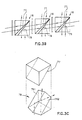
- FIG. 3A and 3B illustrate two alternative typical structures of keyboards constructed and operative in accordance with a preferred embodiment of the present invention.
- each key 16 there is associated with each key 16 a source of illumination such as a LED 57, which is preferably disposed below. Light from each LED 57 passes through a collimating lens 72 and via a color filter 74 into the key 16.
- a source of illumination such as a LED 57, which is preferably disposed below.
- Light from each LED 57 passes through a collimating lens 72 and via a color filter 74 into the key 16.
- the keys 16 are designed to be generally transparent but preferably to include a double sided mirror 76, the bottom facing surface, of which is operative to reflect light from the LED 57 underlying that key, sideways through a display strip 14 and into impingement with the top facing surface of a double sided mirror 76 of an adjacent key and thence upwardly through the generally transparent top surface 78 of the key 16 to the viewer.
- the viewer is thus presented with an image of a symbol or group of symbols which appears on otherwise transparent display strip 14, for each key, indicating the selectable key function.
- Fig. 3B it is seen that instead of a two sided mirror, as in the embodiment of Fig. 3A, alternatively, two separate mirrors 77 and 79 may be employed inside each key 16, without otherwise changing the system. This arrangement enhances illumination of the keys, particularly when the keys are transversely oriented relative to the horizontal.
- Fig. 3C is an exploded view of a key 16.
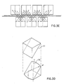
- top and bottom facing mirrors 77 and 79 are provided, but in this embodiment, the bottom facing mirror 79 comprises two angled surfaces 791 and 792, so as to direct the incoming light in two different directions.
- Fig. 3D illustrates an embodiment similar to Fig. 3C but wherein the bottom facing mirror 79 is concave so as to redirect the light in different directions.
- Fig. 3E is a top view of a portion of two adjacent rows of keys where each key redirects the light to two adjacent keys by means of bottom facing mirrors of the type illustrated in Figs. 3C.
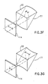
- Fig. 3F shows a detailed view of the top part of a key in which the top facing mirror 77 is seen to be concave, thereby reducing the size of the image of mask 14 formed on the translucent top surface 30 of the key.
- Fig. 3G shows a detailed view of the top portion of a key, in which the top facing mirror 77 is seen to be convex, thereby magnifying the image of mask 14 formed on the translucent top surface 30 of the key.
- Fig. 4 illustrates a structure similar to that of Fig. 3A except that additional lenses 80, comprising either magnification lenses or reduction lenses, are provided in association with each key to provide an enlarged or reduced, as desired, image of the symbol appearing on display strip 14 to the user.
- additional lenses 80 comprising either magnification lenses or reduction lenses
- the remaining elements of the structure of Fig. 4 are essentially similar to those shown in Fig. 3A and are indicated by identical reference numerals.
- FIGs. 5 and 6 illustrate two alternative embodiments of the key configuration employed in the embodiment of Fig. 4.
- a magnifying or reducing lens 80 is located at the surface of the key adjacent the display strip 14, while in Fig. 6, the magnifying or reducing lens 80 is located at the top of the key 16.
- FIG. 7 there is seen a general block diagram of the electrical circuitry employed in accordance with a preferred embodiment of the present invention.
- the invention is described hereinbelow in the context of a personal computer, it being understood, however, that the invention is not at all limited to use with a given computer, type of computer or type of machine.
- the invention may be useful, for example, with electronic typewriters which do not include computing capabilities.
- the invention is seen associated with a general purpose computer 130 such as an IBM PC, XT or AT, which may have graphics hardware and software associated therewith. The provision of graphics hardware and software is not necessary however.
- the computer 130 is typically associated with a conventional CRT display 132.
- a keyboard system 140 constructed and operative in accordance with a preferred embodiment of the invention, is operatively associated with computer 130 and display 132.
- the keyboard system 140 comprises a parallel keyboard interface 142, which is coupled to a parallel port of the computer.
- Circuitry 142 is typically located in the keyboard.
- a serial interface 146 may be provided to communicate with the computer 130, typically via an RS 232 computer port.
- the keyboard circuitry 140 typically comprises a controller 150, based on a CPU module 152 such as an Intel 8031, 8085 or 8086.
- the CPU module 152 interfaces with computer 130 via either of parallel or serial interfaces 142 and 146.
- Parallel interface 142 typically comprises a MC 68488 or a MC 6822 chip from Motorola.
- Serial interface 146 typically comprises a Motorola MC 6850 chip or an Intel 8251 chip and may include RS 232 adapter circuitry 153, such as Motorola 1488 and 1489 chips.
- the controller 150 also interfaces with font &/or graphic ROM/EPROM circuitry 156 typically comprising a graphic EPROM 158, such as an Intel 2732 chip, which stores graphic pixel locations for display strip array 12 (Fig. 1A).
- font &/or graphic ROM/EPROM circuitry 156 typically comprising a graphic EPROM 158, such as an Intel 2732 chip, which stores graphic pixel locations for display strip array 12 (Fig. 1A).
- Chip select instructions to controller 150 are provided by logic circuitry 110, which is illustrated in Fig. 9 and typically is based on a pair of multiplexers such as National 74LS138 chips.
- circuitry 156 is supplied to the display strip array 12 associated with the keyboard 10 via logic circuitry 108, which is illustrated in detail in Fig. 10.
- the logic circuitry 108 comprises a buffer such as a National 74LS373 chip.
- Fig. 10 also illustrates in detail keyboard operation circuitry 266 and LCD driver circuitry 268, which is operative to drive LCD strips 270, which are employed in a preferred embodiment as the display strips 14 (Fig. 1A).
Landscapes
- Engineering & Computer Science (AREA)
- General Engineering & Computer Science (AREA)
- Theoretical Computer Science (AREA)
- Human Computer Interaction (AREA)
- Physics & Mathematics (AREA)
- General Physics & Mathematics (AREA)
- Input From Keyboards Or The Like (AREA)
- Push-Button Switches (AREA)
Applications Claiming Priority (2)
| Application Number | Priority Date | Filing Date | Title |
|---|---|---|---|
| IL91076 | 1989-07-23 | ||
| IL91076A IL91076A (en) | 1989-07-23 | 1989-07-23 | Configurable keyboard |
Publications (3)
| Publication Number | Publication Date |
|---|---|
| EP0410640A2 true EP0410640A2 (de) | 1991-01-30 |
| EP0410640A3 EP0410640A3 (en) | 1991-06-05 |
| EP0410640B1 EP0410640B1 (de) | 1996-05-01 |
Family
ID=11060206
Family Applications (1)
| Application Number | Title | Priority Date | Filing Date |
|---|---|---|---|
| EP90307872A Expired - Lifetime EP0410640B1 (de) | 1989-07-23 | 1990-07-18 | Konfigurierbare Tastatur |
Country Status (11)
| Country | Link |
|---|---|
| US (1) | US5164723A (de) |
| EP (1) | EP0410640B1 (de) |
| JP (1) | JP2780859B2 (de) |
| AT (1) | ATE137594T1 (de) |
| CA (1) | CA2021204C (de) |
| DE (1) | DE69026770T2 (de) |
| DK (1) | DK0410640T3 (de) |
| ES (1) | ES2088974T3 (de) |
| GR (1) | GR3020683T3 (de) |
| IL (1) | IL91076A (de) |
| UA (1) | UA32510A1 (de) |
Cited By (5)
| Publication number | Priority date | Publication date | Assignee | Title |
|---|---|---|---|---|
| WO2003017080A3 (en) * | 2001-08-17 | 2004-02-19 | Danger Inc | A method of dynamically lighting keyboard glyphs |
| WO2004021156A3 (en) * | 2002-08-29 | 2004-12-02 | Clever Stuff Internat Ltd | Method and device for providing direct access to a particular internet website |
| AU781596B2 (en) * | 1999-11-02 | 2005-06-02 | Canal+ Societe Anonyme | Data entry in a GUI |
| WO2007096650A3 (en) * | 2006-02-24 | 2008-05-29 | Innoput Technologies Ltd | Improved computer input device |
| WO2012175087A1 (en) * | 2011-06-24 | 2012-12-27 | Danmarks Tekniske Universitet | Input device with a display configured for dynamic display of key |
Families Citing this family (43)
| Publication number | Priority date | Publication date | Assignee | Title |
|---|---|---|---|---|
| KR950001730B1 (ko) * | 1991-06-08 | 1995-02-28 | 주식회사 일진 | 옵티컬 인텔리젠트 키보드 구조체 |
| KR970004189B1 (ko) * | 1993-02-27 | 1997-03-25 | 삼성전자 주식회사 | 숫자키를 이용한 세트 '온'방법 |
| AU6018494A (en) * | 1993-05-21 | 1994-12-20 | Arthur D. Little Enterprises, Inc. | User-configurable control device |
| US5644303A (en) * | 1993-06-01 | 1997-07-01 | Sony Corporation | Specialized shaped universal remote commander |
| WO1998001876A1 (en) * | 1996-07-03 | 1998-01-15 | Philips Electronics N.V. | Keyboard with multifunction keys and apparatus including such a keyboard |
| US5664896A (en) * | 1996-08-29 | 1997-09-09 | Blumberg; Marvin R. | Speed typing apparatus and method |
| US6169789B1 (en) | 1996-12-16 | 2001-01-02 | Sanjay K. Rao | Intelligent keyboard system |
| US8183998B2 (en) | 1996-12-16 | 2012-05-22 | Ip Holdings, Inc. | System for seamless and secure networking of implantable medical devices, electronic patch devices and wearable devices |
| GB2323331B (en) | 1997-03-21 | 2000-11-22 | Simon Richard Daniel | Collapsible keyboard |
| WO1999024963A1 (en) | 1997-11-12 | 1999-05-20 | Think Outside | Collapsible keyboard |
| KR100477126B1 (ko) | 1997-12-24 | 2005-07-18 | 삼성전자주식회사 | 광다이얼기능을가진컴퓨터 |
| US6004049A (en) * | 1998-10-29 | 1999-12-21 | Sun Microsystems, Inc. | Method and apparatus for dynamic configuration of an input device |
| US6770572B1 (en) | 1999-01-26 | 2004-08-03 | Alliedsignal Inc. | Use of multifunctional si-based oligomer/polymer for the surface modification of nanoporous silica films |
| US6734809B1 (en) | 1999-04-02 | 2004-05-11 | Think Outside, Inc. | Foldable keyboard |
| US6649225B2 (en) * | 1999-04-07 | 2003-11-18 | Board Of Trustees Of Michigan State University | Process for the treatment of a fiber |
| US10728381B2 (en) * | 1999-06-04 | 2020-07-28 | Raman K. Rao | Reconfigurable mobile device interfaces supporting authenticated high quality video, audio, TV and multimedia services |
| US7318019B1 (en) * | 2000-11-17 | 2008-01-08 | Semantic Compaction Systems | Word output device and matrix keyboard for use therein |
| US6781077B2 (en) | 2000-12-14 | 2004-08-24 | Think Outside, Inc. | Keyswitch and actuator structure |
| US6797902B2 (en) | 2001-06-27 | 2004-09-28 | Sotai Ltd. | Illuminable computer keyboard |
| JP2004094898A (ja) * | 2002-08-31 | 2004-03-25 | Tamagawa Seiki Co Ltd | 表示機能内蔵トラックボールおよび表示システム |
| US20040075647A1 (en) * | 2002-10-17 | 2004-04-22 | Bean James J. | Keyboard reconfiguration method and device |
| US7027037B2 (en) * | 2003-04-08 | 2006-04-11 | Intermec Ip Corp. | Conditionally illuminated keypad legends |
| US10140514B1 (en) | 2004-01-30 | 2018-11-27 | Ip Holdings, Inc. | Capturing and sharing images with mobile device users including for a limited duration of time |
| US8965460B1 (en) | 2004-01-30 | 2015-02-24 | Ip Holdings, Inc. | Image and augmented reality based networks using mobile devices and intelligent electronic glasses |
| US11455799B2 (en) | 2004-01-30 | 2022-09-27 | Airspace Reality | Image networks for mobile communication |
| US7872642B2 (en) * | 2004-03-12 | 2011-01-18 | Universal Electronics Inc. | Controlling device having multiple user interfaces |
| US20060007169A1 (en) * | 2004-06-04 | 2006-01-12 | Robbins Michael S | Self-encoding control interface bezel system |
| US20060007168A1 (en) * | 2004-06-04 | 2006-01-12 | Robbins Michael S | Control interface bezel system |
| US20060033720A1 (en) * | 2004-06-04 | 2006-02-16 | Robbins Michael S | Control interface bezel |
| US7629547B2 (en) * | 2006-04-24 | 2009-12-08 | Nokia Corporation | Illuminating of an electrical device |
| US7978179B2 (en) * | 2006-12-06 | 2011-07-12 | International Business Machines Corporation | System and method for configuring a computer keyboard |
| US7622783B2 (en) * | 2007-02-14 | 2009-11-24 | Innovative Micro Technology | MEMS thermal actuator and method of manufacture |
| US7531764B1 (en) | 2008-01-25 | 2009-05-12 | Hewlett-Packard Development Company, L.P. | Keyboard illumination system |
| WO2010030279A1 (en) * | 2008-09-12 | 2010-03-18 | Hewlett-Packard Development Company, L.P. | Keyboard with transparent key pads |
| DE102009044606B4 (de) * | 2009-11-20 | 2015-02-19 | Jean Marc, Diplom-Betriebswirt (BA) Trobrillant | Tastatur |
| US20110248922A1 (en) * | 2010-04-09 | 2011-10-13 | Microsoft Corporation | Adaptive keyboard light pillar |
| DE102011000899A1 (de) | 2011-02-23 | 2012-08-23 | Jean Marc Trobrillant | Eingabevorrichtung |
| US10142496B1 (en) | 2013-01-26 | 2018-11-27 | Ip Holdings, Inc. | Mobile device image capture and image modification including filters, superimposing and geofenced comments in augmented reality |
| US9300645B1 (en) | 2013-03-14 | 2016-03-29 | Ip Holdings, Inc. | Mobile IO input and output for smartphones, tablet, and wireless devices including touch screen, voice, pen, and gestures |
| US11474617B2 (en) * | 2016-06-03 | 2022-10-18 | Key Lights, LLC | Computer keyboard with electronically changeable keycaps |
| US10620715B2 (en) * | 2017-03-20 | 2020-04-14 | International Business Machines Corporation | Programmatic, pluggable keyboard |
| US10963067B2 (en) * | 2019-02-25 | 2021-03-30 | Microsoft Technology Licensing, Llc | Multilayout keyboard |
| US11467676B2 (en) * | 2020-02-06 | 2022-10-11 | Key Ovation, Llc | Computer keyboard with electronically changeable keycaps |
Family Cites Families (19)
| Publication number | Priority date | Publication date | Assignee | Title |
|---|---|---|---|---|
| US1823319A (en) * | 1927-10-11 | 1931-09-15 | Dickinson William Noble | Responsive signal system |
| US2265124A (en) * | 1939-03-20 | 1941-12-09 | Automatic Instr Company | Indexed control apparatus |
| US3611359A (en) * | 1967-12-07 | 1971-10-05 | Maria Panerai | Compact component device for the visible display of letters, digits, symbols and figures |
| DE1941671B2 (de) * | 1969-08-16 | 1970-11-19 | Licentia Gmbh | Programmierbares Tastenfeld |
| US3934243A (en) * | 1973-11-05 | 1976-01-20 | Chevron Research Company | Alphanumeric display means for computer-linked typewriter consoles using a plurality of gaseous glow indicator tube means containing an ionizable gas |
| US3879722A (en) * | 1973-12-10 | 1975-04-22 | Bell Telephone Labor Inc | Interactive input-output computer terminal with automatic relabeling of keyboard |
| GB1524373A (en) * | 1975-02-11 | 1978-09-13 | Lucas Electrical Co Ltd | Electrical switch |
| US4078257A (en) * | 1976-08-23 | 1978-03-07 | Hewlett-Packard Company | Calculator apparatus with electronically alterable key symbols |
| US4163883A (en) * | 1977-12-30 | 1979-08-07 | Texas Instruments Incorporated | Keyboard with illuminated keys |
| US4280121A (en) * | 1978-06-05 | 1981-07-21 | Crask Geoffrey J | Keyboard assembly with controllable key legends |
| FR2488708A2 (fr) * | 1979-09-11 | 1982-02-19 | Rabeisen Andre | Systeme de communication televisuelle permettant une creation graphique |
| US4334210A (en) * | 1980-11-03 | 1982-06-08 | Texas Instruments Incorporated | Thermostatic switch and method of making |
| JPS6089228A (ja) * | 1983-10-19 | 1985-05-20 | Matsushita Electric Ind Co Ltd | キ−ボ−ド |
| US4633227A (en) * | 1983-12-07 | 1986-12-30 | Itt Corporation | Programmable keyboard for a typewriter or similar article |
| GB2181283A (en) * | 1984-09-17 | 1987-04-15 | Janet Braende | Electronically reconfigurable keyboard |
| SU1363176A1 (ru) * | 1985-05-15 | 1987-12-30 | Предприятие П/Я А-3327 | Клавиатура |
| EP0226392A3 (de) * | 1985-12-04 | 1990-04-11 | Henry C. Meadow | Taste und Tastatur mit Anzeige |
| JPS63201685A (ja) * | 1987-02-18 | 1988-08-19 | 鄭 江明 | 透過光と反射光兼用画像板 |
| JPH0731963B2 (ja) * | 1988-04-16 | 1995-04-10 | 東芝ライテック株式会社 | スイッチ装置 |
-
1989
- 1989-07-23 IL IL91076A patent/IL91076A/xx not_active IP Right Cessation
-
1990
- 1990-07-13 CA CA002021204A patent/CA2021204C/en not_active Expired - Fee Related
- 1990-07-17 US US07/553,424 patent/US5164723A/en not_active Expired - Lifetime
- 1990-07-18 ES ES90307872T patent/ES2088974T3/es not_active Expired - Lifetime
- 1990-07-18 DK DK90307872.3T patent/DK0410640T3/da active
- 1990-07-18 EP EP90307872A patent/EP0410640B1/de not_active Expired - Lifetime
- 1990-07-18 AT AT90307872T patent/ATE137594T1/de not_active IP Right Cessation
- 1990-07-18 DE DE69026770T patent/DE69026770T2/de not_active Expired - Fee Related
- 1990-07-20 UA UA4830699A patent/UA32510A1/uk unknown
- 1990-07-23 JP JP2194673A patent/JP2780859B2/ja not_active Expired - Fee Related
-
1996
- 1996-07-31 GR GR960402041T patent/GR3020683T3/el unknown
Cited By (9)
| Publication number | Priority date | Publication date | Assignee | Title |
|---|---|---|---|---|
| AU781596B2 (en) * | 1999-11-02 | 2005-06-02 | Canal+ Societe Anonyme | Data entry in a GUI |
| WO2003017080A3 (en) * | 2001-08-17 | 2004-02-19 | Danger Inc | A method of dynamically lighting keyboard glyphs |
| WO2004021156A3 (en) * | 2002-08-29 | 2004-12-02 | Clever Stuff Internat Ltd | Method and device for providing direct access to a particular internet website |
| WO2007096650A3 (en) * | 2006-02-24 | 2008-05-29 | Innoput Technologies Ltd | Improved computer input device |
| WO2012175087A1 (en) * | 2011-06-24 | 2012-12-27 | Danmarks Tekniske Universitet | Input device with a display configured for dynamic display of key |
| WO2012175086A1 (en) * | 2011-06-24 | 2012-12-27 | Danmarks Tekniske Universitet | Input device with a display configured for dynamic display of key labels |
| CN103765351A (zh) * | 2011-06-24 | 2014-04-30 | 丹麦科技大学 | 具有构造成用于键标记的动态显示的显示器的输入装置 |
| US9239630B2 (en) | 2011-06-24 | 2016-01-19 | Danmarks Tekniske Universitet | Input device with a display configured for dynamic display of key labels |
| CN103765351B (zh) * | 2011-06-24 | 2017-02-22 | 丹麦科技大学 | 具有构造成用于键标记的动态显示的显示器的输入装置 |
Also Published As
| Publication number | Publication date |
|---|---|
| EP0410640A3 (en) | 1991-06-05 |
| DK0410640T3 (da) | 1996-08-12 |
| UA32510A1 (uk) | 2001-02-15 |
| JP2780859B2 (ja) | 1998-07-30 |
| CA2021204C (en) | 2000-01-18 |
| JPH0370018A (ja) | 1991-03-26 |
| ATE137594T1 (de) | 1996-05-15 |
| CA2021204A1 (en) | 1991-01-24 |
| GR3020683T3 (en) | 1996-10-31 |
| IL91076A0 (en) | 1990-03-19 |
| US5164723A (en) | 1992-11-17 |
| DE69026770D1 (de) | 1996-06-05 |
| DE69026770T2 (de) | 1996-11-07 |
| EP0410640B1 (de) | 1996-05-01 |
| ES2088974T3 (es) | 1996-10-01 |
| IL91076A (en) | 1993-02-21 |
Similar Documents
| Publication | Publication Date | Title |
|---|---|---|
| US5164723A (en) | Configurable keyboard | |
| US8959441B2 (en) | Variably displayable mobile device keyboard | |
| US6899273B2 (en) | Optical reader comprising soft key including permanent graphic indicia | |
| US20030001018A1 (en) | Optical reader comprising good read indicator | |
| US5034602A (en) | Optically activated keyboard for digital system having character back lighting | |
| KR100762425B1 (ko) | 디스플레이 유닛 | |
| US5920365A (en) | Display device | |
| US4257041A (en) | Electro optical display device | |
| US4803463A (en) | Key input means with changeable display means for displaying key functions | |
| US5973607A (en) | Hand-held programmable sign | |
| JP2006277013A (ja) | キーボード装置 | |
| KR100527264B1 (ko) | 키보드 장치 및 키보드 키들의 색상을 선정하는 방법 | |
| KR20220014785A (ko) | 포터블 거래 모듈 | |
| EP0226392A2 (de) | Taste und Tastatur mit Anzeige | |
| EP0535401A1 (de) | Kompakte Scheinbild-Anzeige | |
| ES2192656T3 (es) | Terminal de autoservicio. | |
| US20020196198A1 (en) | Active projection screen | |
| GB2241474A (en) | Multifunctional keyboards with changeable keytop indicia | |
| GB2167218A (en) | Computer key and keyboard | |
| WO1999039259A1 (en) | Reconfigurable keyboard | |
| JP4728035B2 (ja) | 表示装置 | |
| JPH075842A (ja) | ネームプレート | |
| JPH0863271A (ja) | キーボード | |
| JP2549380B2 (ja) | 教育学習用拡大投影装置 | |
| JP3523370B2 (ja) | データシンボル読み取り装置 |
Legal Events
| Date | Code | Title | Description |
|---|---|---|---|
| PUAI | Public reference made under article 153(3) epc to a published international application that has entered the european phase |
Free format text: ORIGINAL CODE: 0009012 |
|
| AK | Designated contracting states |
Kind code of ref document: A2 Designated state(s): AT BE CH DE DK ES FR GB GR IT LI LU NL SE |
|
| PUAL | Search report despatched |
Free format text: ORIGINAL CODE: 0009013 |
|
| AK | Designated contracting states |
Kind code of ref document: A3 Designated state(s): AT BE CH DE DK ES FR GB GR IT LI LU NL SE |
|
| 17P | Request for examination filed |
Effective date: 19910717 |
|
| 17Q | First examination report despatched |
Effective date: 19940310 |
|
| GRAH | Despatch of communication of intention to grant a patent |
Free format text: ORIGINAL CODE: EPIDOS IGRA |
|
| GRAA | (expected) grant |
Free format text: ORIGINAL CODE: 0009210 |
|
| AK | Designated contracting states |
Kind code of ref document: B1 Designated state(s): AT BE CH DE DK ES FR GB GR IT LI LU NL SE |
|
| REF | Corresponds to: |
Ref document number: 137594 Country of ref document: AT Date of ref document: 19960515 Kind code of ref document: T |
|
| REF | Corresponds to: |
Ref document number: 69026770 Country of ref document: DE Date of ref document: 19960605 |
|
| ITF | It: translation for a ep patent filed | ||
| REG | Reference to a national code |
Ref country code: DK Ref legal event code: T3 |
|
| REG | Reference to a national code |
Ref country code: CH Ref legal event code: NV Representative=s name: BOVARD AG PATENTANWAELTE |
|
| ET | Fr: translation filed | ||
| REG | Reference to a national code |
Ref country code: GR Ref legal event code: FG4A Free format text: 3020683 |
|
| REG | Reference to a national code |
Ref country code: ES Ref legal event code: FG2A Ref document number: 2088974 Country of ref document: ES Kind code of ref document: T3 |
|
| REG | Reference to a national code |
Ref country code: ES Ref legal event code: FG2A Ref document number: 2088974 Country of ref document: ES Kind code of ref document: T3 |
|
| PLBE | No opposition filed within time limit |
Free format text: ORIGINAL CODE: 0009261 |
|
| STAA | Information on the status of an ep patent application or granted ep patent |
Free format text: STATUS: NO OPPOSITION FILED WITHIN TIME LIMIT |
|
| 26N | No opposition filed | ||
| PGFP | Annual fee paid to national office [announced via postgrant information from national office to epo] |
Ref country code: AT Payment date: 20000712 Year of fee payment: 11 |
|
| REG | Reference to a national code |
Ref country code: GB Ref legal event code: IF02 |
|
| PGFP | Annual fee paid to national office [announced via postgrant information from national office to epo] |
Ref country code: SE Payment date: 20020107 Year of fee payment: 12 |
|
| PGFP | Annual fee paid to national office [announced via postgrant information from national office to epo] |
Ref country code: DK Payment date: 20020108 Year of fee payment: 12 Ref country code: CH Payment date: 20020108 Year of fee payment: 12 |
|
| PGFP | Annual fee paid to national office [announced via postgrant information from national office to epo] |
Ref country code: BE Payment date: 20020109 Year of fee payment: 12 |
|
| PGFP | Annual fee paid to national office [announced via postgrant information from national office to epo] |
Ref country code: LU Payment date: 20020110 Year of fee payment: 12 |
|
| PGFP | Annual fee paid to national office [announced via postgrant information from national office to epo] |
Ref country code: GR Payment date: 20020116 Year of fee payment: 12 |
|
| PGFP | Annual fee paid to national office [announced via postgrant information from national office to epo] |
Ref country code: ES Payment date: 20020125 Year of fee payment: 12 |
|
| PGFP | Annual fee paid to national office [announced via postgrant information from national office to epo] |
Ref country code: DE Payment date: 20020128 Year of fee payment: 12 |
|
| PGFP | Annual fee paid to national office [announced via postgrant information from national office to epo] |
Ref country code: NL Payment date: 20020131 Year of fee payment: 12 |
|
| PG25 | Lapsed in a contracting state [announced via postgrant information from national office to epo] |
Ref country code: LU Free format text: LAPSE BECAUSE OF NON-PAYMENT OF DUE FEES Effective date: 20020718 Ref country code: AT Free format text: LAPSE BECAUSE OF NON-PAYMENT OF DUE FEES Effective date: 20020718 |
|
| PG25 | Lapsed in a contracting state [announced via postgrant information from national office to epo] |
Ref country code: SE Free format text: LAPSE BECAUSE OF NON-PAYMENT OF DUE FEES Effective date: 20020719 Ref country code: ES Free format text: LAPSE BECAUSE OF NON-PAYMENT OF DUE FEES Effective date: 20020719 |
|
| PG25 | Lapsed in a contracting state [announced via postgrant information from national office to epo] |
Ref country code: LI Free format text: LAPSE BECAUSE OF NON-PAYMENT OF DUE FEES Effective date: 20020731 Ref country code: DK Free format text: LAPSE BECAUSE OF NON-PAYMENT OF DUE FEES Effective date: 20020731 Ref country code: CH Free format text: LAPSE BECAUSE OF NON-PAYMENT OF DUE FEES Effective date: 20020731 Ref country code: BE Free format text: LAPSE BECAUSE OF NON-PAYMENT OF DUE FEES Effective date: 20020731 |
|
| BERE | Be: lapsed |
Owner name: *NEBENZAHL ISRAEL D. Effective date: 20020731 |
|
| PG25 | Lapsed in a contracting state [announced via postgrant information from national office to epo] |
Ref country code: NL Free format text: LAPSE BECAUSE OF NON-PAYMENT OF DUE FEES Effective date: 20030201 Ref country code: DE Free format text: LAPSE BECAUSE OF NON-PAYMENT OF DUE FEES Effective date: 20030201 |
|
| PG25 | Lapsed in a contracting state [announced via postgrant information from national office to epo] |
Ref country code: GR Free format text: LAPSE BECAUSE OF NON-PAYMENT OF DUE FEES Effective date: 20030206 |
|
| REG | Reference to a national code |
Ref country code: DK Ref legal event code: EBP |
|
| EUG | Se: european patent has lapsed | ||
| REG | Reference to a national code |
Ref country code: CH Ref legal event code: PL |
|
| NLV4 | Nl: lapsed or anulled due to non-payment of the annual fee |
Effective date: 20030201 |
|
| PGFP | Annual fee paid to national office [announced via postgrant information from national office to epo] |
Ref country code: GB Payment date: 20030716 Year of fee payment: 14 |
|
| PGFP | Annual fee paid to national office [announced via postgrant information from national office to epo] |
Ref country code: FR Payment date: 20030725 Year of fee payment: 14 |
|
| REG | Reference to a national code |
Ref country code: ES Ref legal event code: FD2A Effective date: 20030811 |
|
| PG25 | Lapsed in a contracting state [announced via postgrant information from national office to epo] |
Ref country code: GB Free format text: LAPSE BECAUSE OF NON-PAYMENT OF DUE FEES Effective date: 20040718 |
|
| GBPC | Gb: european patent ceased through non-payment of renewal fee |
Effective date: 20040718 |
|
| PG25 | Lapsed in a contracting state [announced via postgrant information from national office to epo] |
Ref country code: FR Free format text: LAPSE BECAUSE OF NON-PAYMENT OF DUE FEES Effective date: 20050331 |
|
| REG | Reference to a national code |
Ref country code: FR Ref legal event code: ST |
|
| PG25 | Lapsed in a contracting state [announced via postgrant information from national office to epo] |
Ref country code: IT Free format text: LAPSE BECAUSE OF NON-PAYMENT OF DUE FEES;WARNING: LAPSES OF ITALIAN PATENTS WITH EFFECTIVE DATE BEFORE 2007 MAY HAVE OCCURRED AT ANY TIME BEFORE 2007. THE CORRECT EFFECTIVE DATE MAY BE DIFFERENT FROM THE ONE RECORDED. Effective date: 20050718 |