EP0410735A2 - Elektrische und optische Freileitungsübertragungssysteme - Google Patents
Elektrische und optische Freileitungsübertragungssysteme Download PDFInfo
- Publication number
- EP0410735A2 EP0410735A2 EP90308173A EP90308173A EP0410735A2 EP 0410735 A2 EP0410735 A2 EP 0410735A2 EP 90308173 A EP90308173 A EP 90308173A EP 90308173 A EP90308173 A EP 90308173A EP 0410735 A2 EP0410735 A2 EP 0410735A2
- Authority
- EP
- European Patent Office
- Prior art keywords
- conductor
- bore
- optical
- passage
- length
- Prior art date
- Legal status (The legal status is an assumption and is not a legal conclusion. Google has not performed a legal analysis and makes no representation as to the accuracy of the status listed.)
- Ceased
Links
- 230000003287 optical effect Effects 0.000 title claims description 70
- 230000005540 biological transmission Effects 0.000 title claims description 21
- 239000004020 conductor Substances 0.000 claims abstract description 141
- 239000013307 optical fiber Substances 0.000 claims abstract description 47
- 238000000034 method Methods 0.000 claims abstract description 26
- 239000012530 fluid Substances 0.000 claims abstract description 6
- 239000002131 composite material Substances 0.000 claims description 14
- 229910052751 metal Inorganic materials 0.000 claims description 6
- 239000002184 metal Substances 0.000 claims description 6
- 229910001092 metal group alloy Inorganic materials 0.000 claims description 6
- 230000000694 effects Effects 0.000 claims description 4
- 230000006835 compression Effects 0.000 claims description 3
- 238000007906 compression Methods 0.000 claims description 3
- 230000002939 deleterious effect Effects 0.000 claims description 2
- 239000004411 aluminium Substances 0.000 description 6
- 229910052782 aluminium Inorganic materials 0.000 description 6
- XAGFODPZIPBFFR-UHFFFAOYSA-N aluminium Chemical compound [Al] XAGFODPZIPBFFR-UHFFFAOYSA-N 0.000 description 6
- 238000004519 manufacturing process Methods 0.000 description 3
- 238000013459 approach Methods 0.000 description 1
- 238000003780 insertion Methods 0.000 description 1
- 230000037431 insertion Effects 0.000 description 1
- 239000000463 material Substances 0.000 description 1
- 229920003023 plastic Polymers 0.000 description 1
- 230000000007 visual effect Effects 0.000 description 1
Images
Classifications
-
- G—PHYSICS
- G02—OPTICS
- G02B—OPTICAL ELEMENTS, SYSTEMS OR APPARATUS
- G02B6/00—Light guides; Structural details of arrangements comprising light guides and other optical elements, e.g. couplings
- G02B6/46—Processes or apparatus adapted for installing or repairing optical fibres or optical cables
- G02B6/50—Underground or underwater installation; Installation through tubing, conduits or ducts
- G02B6/52—Underground or underwater installation; Installation through tubing, conduits or ducts using fluid, e.g. air
-
- G—PHYSICS
- G02—OPTICS
- G02B—OPTICAL ELEMENTS, SYSTEMS OR APPARATUS
- G02B6/00—Light guides; Structural details of arrangements comprising light guides and other optical elements, e.g. couplings
- G02B6/44—Mechanical structures for providing tensile strength and external protection for fibres, e.g. optical transmission cables
- G02B6/4401—Optical cables
- G02B6/4415—Cables for special applications
- G02B6/4416—Heterogeneous cables
-
- G—PHYSICS
- G02—OPTICS
- G02B—OPTICAL ELEMENTS, SYSTEMS OR APPARATUS
- G02B6/00—Light guides; Structural details of arrangements comprising light guides and other optical elements, e.g. couplings
- G02B6/44—Mechanical structures for providing tensile strength and external protection for fibres, e.g. optical transmission cables
- G02B6/4401—Optical cables
- G02B6/4415—Cables for special applications
- G02B6/4416—Heterogeneous cables
- G02B6/4422—Heterogeneous cables of the overhead type
Definitions
- This invention relates to an overhead electric and optical transmission system comprising at least one flexible electric conductor incorporating at least one optical fibre suspended freely in long lengths between towers or other upstanding supports mutually spaced along the route of the system.
- the route of an overhead electric transmission system can extend for several kilometres and, when suspending a flexible overhead electric conductor between mutually spaced towers or other upstanding supports of the system it is necessary to interconnect end-to-end, both electrically and mechanically, several individual lengths of flexible conductor because the length of any one of these conductors is limited by the amount of conductor that can be readily wound on a cable drum without damaging the conductor. Thus, in suspending a conductor along the entire route of an overhead electric transmission system, many conductor joints have to be effected.
- one or more than one optical fibre splice or joint must also be effected, depending upon the number of optical fibres in the conductor, thereby substantially increasing the time spent in and hence the cost of suspending the composite conductor in the system.
- an optical fibre can be manufactured and wound on a drum or reel, without any splices or joints in the optical fibre, in a length of many kilometres and, in most circumstances, in a length substantially greater than the length of the route of an overhead electric and optical transmission system.
- adjacent lengths of conductor are so electrically and mechanically connected end-to-end that the bores or other passages of said interconnected conductor lengths are substantially smoothly continuous and, after the conductor comprising said interconnected conductor lengths is suspended between a plurality of towers or other upstanding supports mutually spaced along the route of the system, at least one length of flexible optical guide comprising at least one optical fibre is accommodated throughout the length of at least one substantially smoothly continuous bore or other passage within the suspended conductor by introducing a leading end of the length of optical guide into an end of the bore or passage and by propelling the optical guide along the bore or passage of the suspended conductor by fluid drag of a gaseous medium which will have no deleterious effect on the optical guide or on the conductor and which is passed through the bore or passage in the desired direction of advance at such a pressure that the length of optical guide is carried along the bore or passage until the length of optical guide is loosely housed in and throughout the length of said bore or passage of the suspended conductor.
- the length of optical guide is so accommodated in the substantially smoothly continuous bore or other passage of the suspended conductor that it will substantially exceed the length of the bore or passage so that there is an excess length of optical guide within the bore or passage.
- substantially smoothly continuous as used to describe the bore or other passage within the suspended conductor is meant a bore or other passage having no step or other abutment protruding into the bore or other passage at the position of a conductor joint or elsewhere in the length of conductor which might inhibit or restrict carriage of a flexible optical guide along the bore or other passage by the gaseous medium flowing along the bore or passage.
- Adjacent lengths of conductor may be electrically and mechanically connected end-to-end after each conductor length has been strung between towers or other upstanding supports of the overhead electric and optical transmission system but, preferably, said adjacent lengths of conductor are electrically and mechanically connected end-to-end before the conductor comprising said interconnected conductor lengths is strung between the towers or other upstanding supports of the system.
- Individual lengths of conductor having within and extending throughout the length of conductor at least one bore or other passage may be electrically or mechanically connected end-to-end by any method which will ensure that the bores or other passages of the interconnected conductor lengths are substantially smoothly continuous.
- each conductor length comprises one or more than one layer of bare elongate elements of metal or metal alloy helically wound around a substantially circumferentially rigid central core having at least one bore or other passage within and extending throughout the length of the core, two such conductor lengths are preferably electrically and mechanically connected end-to-end by means of a sleeve of metal or metal alloy which overlies adjacent end parts of the conductor lengths - that have been so aligned that the axes of the bores or other passages of the conductor lengths are co-linear - and which is compression jointed or otherwise permanently secured to said neighbouring end parts of the conductor lengths.
- Stringing of the conductor consisting of said two or more interconnected conductor lengths between a plurality of towers or other upstanding supports mutually spaced along the route of the system can be effected by any known technique.
- the or each flexible optical guide is propelled along the bore or other passage of the suspended conductor by fluid drag of the gaseous medium using the method and apparatus as described and claimed in our British Patent No: 2179471B, which method comprises rotatably mounting within a substantially fluid-tight housing a reel or spool on which said length of flexible optical guide is wound and feeding the leading end of the optical guide through an outlet of the housing into one end of said bore or other passage within the suspended conductor; directly or indirectly connecting the outlet of the housing to said end of the bore or other passage in such a way as to effect a fluid-tight seal; unwinding the optical guide from the reel or spool by a driving mechanism; and continuously introducing the gaseous medium into the fluid-tight housing, the rate at which the optical guide is unwound from the reel or spool by said driving mechanism and the pressure and rate at which the gaseous medium is continuously introduced into the fluid-tight housing being such that the optical guide is carried along said bore or other passage by a combination of said drive and
- the or each flexible optical guide to be accommodated in said at least one substantially smoothly continuous bore or other passage within the suspended conductor may be a separate optical fibre or it may be an optical fibre element comprising two or more optical fibres assembled together such as, for example, an optical fibre ribbon comprising a plurality of optical fibres extending side by side with their axes lying in a substantially common plane.
- an optical fibre ribbon structure which is especially suitable for use in the improved method of the present invention is described and claimed in the specification of our British Patent No: 2141558B.
- the invention further includes an overhead electric and optical transmission system comprising at least one composite flexible electric and optical conductor suspended freely in long lengths between towers or other upstanding supports mutually spaced along the route of the system, which conductor has within and extending throughout the length of the conductor at least one bore or other passage in which at least one optical fibre is loosely housed, wherein the composite conductor comprises at least two lengths of flexible electric conductor electrically and mechanically connected end to end in such a way that the bores or other passages of interconnected conductor lengths are substantially smoothly continuous and wherein the number of optical fibre splices or joints in the or each optical fibre loosely housed in said at least one smoothly continuous bore or other passage of the interconnected conductor lengths of the suspended conductor is less than the number of electrical and mechanical connections between said conductor lengths.
- the or each optical fibre loosely housed in said at least one smoothly continuous bore or other passage of the interconnected conductor lengths of the suspended conductor has no optical fibre splice or joint therein.
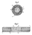
- the composite conductor 1 shown in Figure 1 comprises a seamless central tubular core 2 of aluminium having a bore 3 in which is loosely housed an optical fibre ribbon 4 comprising a plurality of optical fibres extending side by side with their axes lying in a substantially common plane, the length of the optical fibre ribbon being substantially greater than the length of the bore.
- the central core 2 is surrounded by two stranded layers 5 and 6 of round bare wires of aluminium, the directions of lay of the stranded layers being of opposite hand.
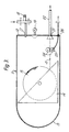
- the aluminium tube 8 has a length such that the ends of the exposed lengths of the central cores 2 abut, has an internal diameter such that the exposed lengths of the central cores are a substantially tight fit in the bore of the tube and has an outer diameter substantially equal to the overall diameters of the conductors 1.
- the tube 8 serves to maintain the exposed lengths of the central cores 2 in substantially axial alignment with their end faces abutting and with their bores 3 substantially smoothly continuous.
- the ferrule 9 is then arranged to overlie the aluminium tube 8 and adjacent parts of the conductors 1 and the ferrule is compression jointed to the conductors and to the tube to effect a mechanical and electrical joint between the conductors.
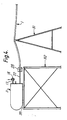
- the preferred apparatus shown in Figure 3 comprises a substantially fluid-tight housing 11 of elongate shape having, at one end of the housing, an end wall 12 and, at the other end of the housing, an end wall 13 of hemi-spherical shape.
- a pay-off stand 14 mounted in the housing 11 is a pay-off stand 14 on which can be freely rotatably mounted a reel 15 on which is wound an optical fibre ribbon 4.
- an inlet port 17 through which pressurised air from a source (not shown) can be introduced into the housing, the rate of introduction of the air being controllable by a valve 18.
- a visual indication of the pressure of the air within the housing 11 can be given by a pressure meter 19.
- a pipe 22 of transparent plastics material for insertion into the bore 3 of the central core 2 of the suspended conductor 1 into which optical fibre ribbon 4 from the reel 15 is to be introduced.
- a pair of rubber-coated pinch wheels 24 Positioned within the housing 11 between the reel and the outlet 21 is a pair of rubber-coated pinch wheels 24, one of which can be rotatably driven through a gearbox (not shown) by a 12 v.d.c. electric motor 25, the leads from the motor passing through a fluid-tight seal in an aperture 26 in the end wall 12 via an electro mechanical relay (not shown), controlled by a programmable controller, to a power supply (not shown).
- the housing 11 may have at least one window in its wall and may incorporate an internal lighting system to enable the behaviour of the optical fibre ribbon 4 and the reel 15 to be continuously monitored, thereby giving an indication of any obstruction in the bore 3 of the suspended conductor 1.
- scaffolding 32 supporting a platform 33 is erected adjacent the tower at one end of the system and apparatus as shown in Figure 3, containing a reel 15 on which optical fibre ribbon 4 is wound, is disposed on the platform.
- Individual lengths of flexible electric conductor, each having within and extending along the length of conductor a central tubular core 12 having a bore 3 are electrically and mechanically connected end-to-end by the method as described with reference to and illustrated in Figure 2 in such a way that the bores 3 of interconnected conductor lengths are smoothly continuous.
- the conductor 1 consisting of these interconnected conductor lengths is then strung between the towers 31 mutually spaced along the route of the system by any known technique.
- pipe 22 of the apparatus mounted on the platform 33 is introduced into the bore 3 of the suspended conductor 1 at one end of the conductor and is locked to the conductor by any appropriate locking means 28.
- Optical fibre ribbon 4 is passed from the reel 15 via a guide tube (not shown) between and in contact with the pair of wheels 24, through another guide tube (not shown), through the pipe 22 and, by means of the motor 25, is fed a short distance into the smoothly continuous bore 3 of the suspended conductor 1.
- Air under pressure is then introduced into the housing 11 through the inlet port 17 so that the housing is substantially filled with air at a predetermined pressure, the hemi-spherical end wall 13 of the housing being so shaped as to deflect the air smoothly so that it flows towards and out of the outlet 21 through the pipe 22 and into the smoothly continuous bore 3 of the suspended conductor 1.
- the pair of wheels 24 is rotatably driven by the motor 25 at continuously variable speeds between upper and lower limits to produce a pulsing effect serving to provide an intermittent release of optical fibre ribbon 4 from the reel 15.
- the rate at which the optical fibre ribbon 4 is unwound intermittently from the reel 15 by the pair of wheels 24 and the pressure and rate at which air is continuously introduced into the fluid-tight housing 11 are such that regular pulsed progression of the optical fibre ribbon along the pipe 22 and into the smoothly continuous bore 3 of the suspended conductor 1 is produced by a combination of the continuously varied drive and fluid drag of the air.
- the process is continued until the desired length of optical fibre ribbon 4 is loosely housed in and throughout the length of the smoothly continuous bore 3 of the suspended conductor 1.
- the pressure of air introduced into the housing 11 will depend on the relative transverse dimensions of the bore 3 of the suspended conductor 1 and the optical fibre ribbon 4 and on the length of bore into which the optical fibre ribbon is to be introduced.
- the pressure of air introduced into the housing 11 preferably lies in the range 50 to 150 psi but pressures substantially greater than this can be employed.
- the improved method of the present invention also has the very important advantage that the cost of manufacture of the flexible overhead electric conductor is itself substantially reduced since it is no longer necessary to incorporate the or each flexible optical guide into the conductor during its manufacture.
- the conductor comprises one or more than one layer of bare elongate elements of metal or metal alloy helically wound around a substantially circumferentially rigid central core having a central bore within and extending throughout the length of the core, the central core can be seamless.
- the conductor joint no or very few optical fibre splices or joints are required to be effected in the field, thereby substantially reducing risk of any unsatisfactory optical fibre splices or joints in the overhead optical transmission system that might otherwise be present.
Landscapes
- Physics & Mathematics (AREA)
- General Physics & Mathematics (AREA)
- Optics & Photonics (AREA)
- Communication Cables (AREA)
- Light Guides In General And Applications Therefor (AREA)
- Mechanical Coupling Of Light Guides (AREA)
Applications Claiming Priority (2)
| Application Number | Priority Date | Filing Date | Title |
|---|---|---|---|
| GB8917347 | 1989-07-28 | ||
| GB898917347A GB8917347D0 (en) | 1989-07-28 | 1989-07-28 | Overhead electric and optical transmission systems |
Publications (2)
| Publication Number | Publication Date |
|---|---|
| EP0410735A2 true EP0410735A2 (de) | 1991-01-30 |
| EP0410735A3 EP0410735A3 (en) | 1991-10-02 |
Family
ID=10660816
Family Applications (1)
| Application Number | Title | Priority Date | Filing Date |
|---|---|---|---|
| EP19900308173 Ceased EP0410735A3 (en) | 1989-07-28 | 1990-07-25 | Overhead electric and optical transmission systems |
Country Status (10)
| Country | Link |
|---|---|
| US (1) | US5123075A (de) |
| EP (1) | EP0410735A3 (de) |
| JP (1) | JPH03137603A (de) |
| CN (1) | CN1029443C (de) |
| AR (1) | AR243306A1 (de) |
| AU (1) | AU627608B2 (de) |
| CA (1) | CA2021971A1 (de) |
| GB (2) | GB8917347D0 (de) |
| MY (1) | MY106850A (de) |
| NZ (1) | NZ234654A (de) |
Cited By (10)
| Publication number | Priority date | Publication date | Assignee | Title |
|---|---|---|---|---|
| WO1993017361A1 (en) * | 1992-02-28 | 1993-09-02 | Comm/Scope, Inc. | Method for upgrading a coaxial cable with a fiber optic cable |
| WO1993023779A1 (en) * | 1992-05-09 | 1993-11-25 | Bicc Public Limited Company | Overhead optical transmission system |
| EP0780713A1 (de) * | 1995-12-22 | 1997-06-25 | PIRELLI GENERAL plc | Freileiter für eine faseroptische Einheit |
| DE10005077A1 (de) * | 2000-02-04 | 2001-08-09 | Alcatel Sa | Optisches Kabel |
| EP0746073B2 (de) † | 1995-05-30 | 2002-10-16 | Siemens Aktiengesellschaft | Verfahren zur Installation eines Lichtwellenleiter-Kabels an einer Hochspannungsfreileitung |
| US7106931B2 (en) | 2001-11-19 | 2006-09-12 | Pirelli General Plc | Optical fiber drop cables |
| US7783147B2 (en) | 2001-11-19 | 2010-08-24 | Prysmian Cables & Systems Limited | Optical fibre drop cables |
| WO2016009305A1 (en) * | 2014-07-16 | 2016-01-21 | Tyco Electronics (Shanghai) Co., Ltd | Connection device for optical and electric hybrid cable |
| WO2016016762A1 (en) * | 2014-07-31 | 2016-02-04 | Tyco Electronics (Shanghai) Co. Ltd | Method for connecting first and second optical and electric hybrid cables |
| EP3373057A1 (de) * | 2017-03-07 | 2018-09-12 | Tratos Cavi S.p.A. | Lichtleiterkabel für freileitungen und verfahren zu dessen implementierung |
Families Citing this family (12)
| Publication number | Priority date | Publication date | Assignee | Title |
|---|---|---|---|---|
| GB9006210D0 (en) * | 1990-03-20 | 1990-05-16 | Bicc Plc | Overhead electric and optical conductor manufacture |
| GB9008028D0 (en) * | 1990-04-09 | 1990-06-06 | Metal Manufactures Ltd | Composite electric and optical cable manufacture |
| US5448670A (en) * | 1994-06-10 | 1995-09-05 | Commscope, Inc. | Elliptical aerial self-supporting fiber optic cable and associated apparatus and methods |
| US5503370A (en) * | 1994-07-08 | 1996-04-02 | Ctes, Inc. | Method and apparatus for the injection of cable into coiled tubing |
| US5599004A (en) * | 1994-07-08 | 1997-02-04 | Coiled Tubing Engineering Services, Inc. | Apparatus for the injection of cable into coiled tubing |
| GB9419079D0 (en) * | 1994-09-22 | 1994-11-09 | Bicc Plc | Method and apparatus for installing an optical fibre element in a tube |
| US6012621A (en) | 1997-09-04 | 2000-01-11 | Condux International, Inc. | Cable conveying apparatus |
| ITMI981658A1 (it) | 1998-07-20 | 2000-01-20 | Pirelli Cavi E Sistemi Spa | Cavo ibrido elettrico ed ottico per installazioni aeree |
| US6827076B2 (en) * | 2003-02-07 | 2004-12-07 | Original Ideas Inc. | Quick start barbecue |
| KR101652201B1 (ko) * | 2015-06-30 | 2016-08-30 | 김상철 | 난방배관 내부에 히팅케이블을 주입하기 위한 장치 및 방법 |
| JP7169276B2 (ja) * | 2017-01-05 | 2022-11-10 | リンテック・オヴ・アメリカ,インコーポレイテッド | ナノファイバー糸ディスペンサー |
| US10843891B2 (en) | 2017-01-05 | 2020-11-24 | Lintec Of America, Inc. | Nanofiber yarn dispenser |
Family Cites Families (13)
| Publication number | Priority date | Publication date | Assignee | Title |
|---|---|---|---|---|
| CA1112310A (en) * | 1977-05-13 | 1981-11-10 | Peter Fearns | Overhead electric transmission systems |
| GB1598438A (en) * | 1977-05-13 | 1981-09-23 | Bicc Ltd | Overhead electric transmission systems |
| US4185809A (en) * | 1978-01-27 | 1980-01-29 | Nelson Jonnes | Method and apparatus for pulling lightweight cable |
| CA1217369A (en) * | 1981-06-18 | 1987-02-03 | Peter Harvey | Overhead electric transmission systems |
| GB8309671D0 (en) * | 1982-11-08 | 1983-05-11 | British Telecomm | Optical fibre transmission lines |
| EP0108590B1 (de) * | 1982-11-08 | 1986-11-26 | BRITISH TELECOMMUNICATIONS public limited company | Optische Übertragungsfasern |
| GB8316494D0 (en) * | 1983-06-17 | 1983-07-20 | Bicc Plc | Flexible elongate body |
| DE3329792C2 (de) * | 1983-08-18 | 1987-04-02 | Kabelwerke Brugg AG, Brugg | Dreiadriges Mittelspannungskabel mit Kabelmantel |
| GB8520692D0 (en) * | 1985-08-19 | 1985-09-25 | Bicc Plc | Optical cable element |
| JPS6290602A (ja) * | 1985-10-17 | 1987-04-25 | Sumitomo Electric Ind Ltd | 光フアイバユニツトの引替工法 |
| JPS63188106A (ja) * | 1987-01-30 | 1988-08-03 | Showa Electric Wire & Cable Co Ltd | 光フアイバケ−ブルの架空地線への引き入れ方法 |
| GB8727581D0 (en) * | 1987-11-25 | 1987-12-31 | Optical Fibres | Method and apparatus for blowing optical fibre member |
| GB8823427D0 (en) * | 1988-10-05 | 1988-11-09 | British Telecomm | Gas seal |
-
1989
- 1989-07-28 GB GB898917347A patent/GB8917347D0/en active Pending
-
1990
- 1990-07-24 US US07/556,450 patent/US5123075A/en not_active Expired - Fee Related
- 1990-07-25 CA CA002021971A patent/CA2021971A1/en not_active Abandoned
- 1990-07-25 EP EP19900308173 patent/EP0410735A3/en not_active Ceased
- 1990-07-25 GB GB9016338A patent/GB2235595B/en not_active Expired - Fee Related
- 1990-07-26 NZ NZ234654A patent/NZ234654A/en unknown
- 1990-07-27 AU AU59914/90A patent/AU627608B2/en not_active Ceased
- 1990-07-27 AR AR90317486A patent/AR243306A1/es active
- 1990-07-27 MY MYPI90001267A patent/MY106850A/en unknown
- 1990-07-28 CN CN90107258.3A patent/CN1029443C/zh not_active Expired - Fee Related
- 1990-07-30 JP JP2199343A patent/JPH03137603A/ja active Pending
Cited By (14)
| Publication number | Priority date | Publication date | Assignee | Title |
|---|---|---|---|---|
| US5293678A (en) * | 1992-02-28 | 1994-03-15 | Comm/Scope | Method for upgrading and converting a coaxial cable with a fiber optic cable |
| WO1993017361A1 (en) * | 1992-02-28 | 1993-09-02 | Comm/Scope, Inc. | Method for upgrading a coaxial cable with a fiber optic cable |
| WO1993023779A1 (en) * | 1992-05-09 | 1993-11-25 | Bicc Public Limited Company | Overhead optical transmission system |
| US5513292A (en) * | 1992-05-09 | 1996-04-30 | Bicc Public Ltd. Co. | Overhead optical transmission system |
| EP0746073B2 (de) † | 1995-05-30 | 2002-10-16 | Siemens Aktiengesellschaft | Verfahren zur Installation eines Lichtwellenleiter-Kabels an einer Hochspannungsfreileitung |
| EP0780713A1 (de) * | 1995-12-22 | 1997-06-25 | PIRELLI GENERAL plc | Freileiter für eine faseroptische Einheit |
| US5727106A (en) * | 1995-12-22 | 1998-03-10 | Pirelli General Plc | Suspended line for an optical fibre unit |
| DE10005077A1 (de) * | 2000-02-04 | 2001-08-09 | Alcatel Sa | Optisches Kabel |
| US6608953B2 (en) | 2000-02-04 | 2003-08-19 | Alcatel | Optical cable having a metallic core with a channel containing an optical waveguide |
| US7106931B2 (en) | 2001-11-19 | 2006-09-12 | Pirelli General Plc | Optical fiber drop cables |
| US7783147B2 (en) | 2001-11-19 | 2010-08-24 | Prysmian Cables & Systems Limited | Optical fibre drop cables |
| WO2016009305A1 (en) * | 2014-07-16 | 2016-01-21 | Tyco Electronics (Shanghai) Co., Ltd | Connection device for optical and electric hybrid cable |
| WO2016016762A1 (en) * | 2014-07-31 | 2016-02-04 | Tyco Electronics (Shanghai) Co. Ltd | Method for connecting first and second optical and electric hybrid cables |
| EP3373057A1 (de) * | 2017-03-07 | 2018-09-12 | Tratos Cavi S.p.A. | Lichtleiterkabel für freileitungen und verfahren zu dessen implementierung |
Also Published As
| Publication number | Publication date |
|---|---|
| GB9016338D0 (en) | 1990-09-12 |
| GB2235595A (en) | 1991-03-06 |
| EP0410735A3 (en) | 1991-10-02 |
| JPH03137603A (ja) | 1991-06-12 |
| CN1049916A (zh) | 1991-03-13 |
| CN1029443C (zh) | 1995-08-02 |
| AU627608B2 (en) | 1992-08-27 |
| CA2021971A1 (en) | 1991-01-29 |
| GB8917347D0 (en) | 1989-09-13 |
| US5123075A (en) | 1992-06-16 |
| MY106850A (en) | 1995-08-30 |
| AR243306A1 (es) | 1993-07-30 |
| AU5991490A (en) | 1991-02-21 |
| GB2235595B (en) | 1993-11-03 |
| NZ234654A (en) | 1992-09-25 |
Similar Documents
| Publication | Publication Date | Title |
|---|---|---|
| US5123075A (en) | Overhead electric and optical transmission systems | |
| US4691896A (en) | Optical fibre transmission line | |
| US4796970A (en) | Optical fibre transmission lines | |
| US5645267A (en) | Method and apparatus for installing transmission lines | |
| US4948097A (en) | Method and apparatus for installing transmission lines | |
| JPH02265109A (ja) | 複合ケーブルおよび光ファイバの挿通方法 | |
| KR860000050B1 (ko) | 가요성 연선의 제조방법 및 장치 | |
| EP0410736A2 (de) | Installation von elektrischen Kabeln | |
| US5234198A (en) | Apparatus for installing optical fiber in conduit | |
| US5121901A (en) | Sheathed optical fibres and method of installing such fibres | |
| EP0452088B1 (de) | Herstellung eines elektrisch-optischen Kabels | |
| AU632912B2 (en) | Overhead electric and optical conductor manufacture | |
| CA2038787A1 (en) | Overhead electric and optical conductor manufacture | |
| JPH0980282A (ja) | 光ファイバケーブルの布設方法及び装置 | |
| EP0458607A1 (de) | Freileitungssystem mit elektrischen und optischen Leitern | |
| JPH04161902A (ja) | 光ファイバケーブル及び長尺線材の布設方法 | |
| SE515545C2 (sv) | Förfarande för skarvning av två optiska fiberkablar samt skarv mellan sådana kablar |
Legal Events
| Date | Code | Title | Description |
|---|---|---|---|
| PUAI | Public reference made under article 153(3) epc to a published international application that has entered the european phase |
Free format text: ORIGINAL CODE: 0009012 |
|
| AK | Designated contracting states |
Kind code of ref document: A2 Designated state(s): AT BE CH DE DK ES FR GB GR IT LI LU NL SE |
|
| 17P | Request for examination filed |
Effective date: 19910424 |
|
| PUAL | Search report despatched |
Free format text: ORIGINAL CODE: 0009013 |
|
| AK | Designated contracting states |
Kind code of ref document: A3 Designated state(s): AT BE CH DE DK ES FR GB GR IT LI LU NL SE |
|
| 17Q | First examination report despatched |
Effective date: 19930406 |
|
| STAA | Information on the status of an ep patent application or granted ep patent |
Free format text: STATUS: THE APPLICATION HAS BEEN REFUSED |
|
| 18R | Application refused |
Effective date: 19951209 |