EP0410741A2 - Appareil pour le transport d'un stencil - Google Patents
Appareil pour le transport d'un stencil Download PDFInfo
- Publication number
- EP0410741A2 EP0410741A2 EP90308181A EP90308181A EP0410741A2 EP 0410741 A2 EP0410741 A2 EP 0410741A2 EP 90308181 A EP90308181 A EP 90308181A EP 90308181 A EP90308181 A EP 90308181A EP 0410741 A2 EP0410741 A2 EP 0410741A2
- Authority
- EP
- European Patent Office
- Prior art keywords
- stencil
- rollers
- feed roller
- guide plate
- driven
- Prior art date
- Legal status (The legal status is an assumption and is not a legal conclusion. Google has not performed a legal analysis and makes no representation as to the accuracy of the status listed.)
- Granted
Links
Images

Classifications
-
- B—PERFORMING OPERATIONS; TRANSPORTING
- B41—PRINTING; LINING MACHINES; TYPEWRITERS; STAMPS
- B41L—APPARATUS OR DEVICES FOR MANIFOLDING, DUPLICATING OR PRINTING FOR OFFICE OR OTHER COMMERCIAL PURPOSES; ADDRESSING MACHINES OR LIKE SERIES-PRINTING MACHINES
- B41L31/00—Devices for removing flexible printing formes from forme cylinders
Definitions
- This invention relates to a stencil carrier apparatus, and more particularly to a stencil carrier apparatus which is incorporated into a stencil discharging section of a printing apparatus and transports a used stencil from a printing drum to a predetermined position.
- a printing apparatus such as a mimeo-graphic printing apparatus or an offset printing apparatus
- various types of stencil discharging devices have been heretofore developed so as to automatically remove a used stencil from a printing drum and discharge the same to a pre-determined position.
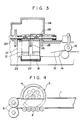
- FIG. 4 of the accompanying drawing shows one of such apparatuses, which is exemplified in Japanese Patent Publication No. 54780/3986.
- a plurality of driven feed rollers 2 are disposed at the bottom of a stencil receiver 1.
- the semi-cylindrical portion of the driving roller 3 is covered with an elastic member 4, through which the driving roller 3 is pressed toward the driven feed rollers 2 when it rotates with its semi-cylindrical portion coming downwards.
- Discharge rollers 5 are disposed downstream of the driving feed roller 3, and discharge used stencils into a box, not shown.
- a stencil carrier apparatus comprising: driven feed rollers, a driving feed roller which is in semi-cylindrical shape and transports a used stencil from a printing drum while holding the used stencil in co-operation with the driven rollers, a pressure guide plate which is pushed toward the driven feed rollers in synchronization with rotation of the driving feed roller so as to have the stencil held between the drive feed roller and the driven feed rollers during transportation of the stencil, and a control cam to be operated in synchronization with the driving feed roller and to keep the pressure guide plate pushed toward the driven rollers while a used stencil is being transported by the driving feed roller.
- the pressure guide plate is made of an elastic material, is disposed downstream of the driving feed roller and has a fixed rear end and a free forward end viewed in the feeding direction of the stencil. Further, the driving feed roller is divided around a groove at the center thereof in the axial direction, and has a part of the pressure guide plate positioned in said groove.
- the stencil carrier apparatus is for use in a stencil discharging apparatus for a mimeographic printing machine.
- a stencil receiver 10 is attached on a side of the printing machine by means of a hinge 12 located at a ceiling 11.
- the stencil receiver 10 can be opened and shut.
- the stencil receiver 10 has an intake port 14 on its front side so as to receive the used stencils, and an outlet port 15 on the right side thereof.
- at the intake port 14 there are disposed intake rollers 16 whose axes are in parallel with the printing drum.
- the intake rollers 16 are arranged so that they can receive the used stencils from the printing drum and transport them to the stencil receiver 10.
- discharge rollers 17 are disposed at the outlet port 15 with their axes come into contact with the intake rollers 16 at right angles, so that the used stencil can be discharged into a box (not shown) located outside the stencil receiver.
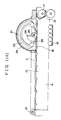
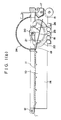
- a plurality of the driven feed rollers 18 are disposed adjacent the discharge rollers 17 as shown in FIGS. 1 and 2.
- Rotary shafts of the driven rollers 18 are in parallel with the rotary shafts of the discharge rollers 17.
- the ceiling 11 is formed with a rectangular opening 19, at which a driving roller 21 is disposed.
- the driving shaft 20 of the driving roller 21 is in parallel with the driving shafts of the rollers 18 and 17.
- the driving roller 21 is sector-shaped and has its semi-cylindrical portion covered with an elastic member 22 having a large frictional resistance.
- the driving roller 21 is divided into two around a groove 23 at the center thereof in the direction of the drive shaft 20.
- a semi-cylindrical cover 24 is disposed on the opening 19 of the ceiling 11 under which the driving roller 21 is positioned. The cover 24 covers the driving roller 21 when its semi-cylindrical portion comes upward with the rotation thereof.
- an elongate pressure guide plate 25 made of an elastic material is disposed at the opening 19.
- the pressure guide plate 25 is as long as the diameter of the driving roller 21, and is positioned horizontally in the gap between the driving roller 21 and the groove 23 , and between the driving roller 21 and the opening 19. Viewed in the stencil feeding direction, the rear end of the guide plate 25 is fixed to the ceiling 11, and the other end of the guide plate 25 is free.
- a control cam 26 for controlling the guide plate 25 is fixedly mounted on the drive shaft 20 of the driving roller 21. As the driving roller 21 rotates to carry the stencil, the control cam 26 pushes the guide plate 25 downwards to have it flexed. As can be seen in FIG. 1(b), when the driving roller 21 engages with the driven rollers 18 at the lowest position, the pressure guide plate 25 is flexed to the maximum extent by the control cam 26.
- the pressure guide plate 25 depresses downwardly the leading edge of the stencil held between the driving and driven rollers 18, 21, thereby enabling the stencil to be carried without being lifted or curled, or without being wound around the driving roller 21 or around the drive shaft 20. Then the stencil is transported toward the outlet port 15 of the stencil receiver 10 by the guide of the guide plate 25, and is finally discharged into the box outside the stencil carrier apparatus.
- the pressure guide plate is designed so as to hold the stencil downwardly in synchronization with the rotation of the driving roller, it is possible to keep the stencil from being lifted or curled, and to transport the stencil reliably to the pre-determined position.
Landscapes
- Delivering By Means Of Belts And Rollers (AREA)
- Supply, Installation And Extraction Of Printed Sheets Or Plates (AREA)
- Separation, Sorting, Adjustment, Or Bending Of Sheets To Be Conveyed (AREA)
Applications Claiming Priority (2)
| Application Number | Priority Date | Filing Date | Title |
|---|---|---|---|
| JP1989086511U JPH081887Y2 (ja) | 1989-07-25 | 1989-07-25 | 原版の搬送装置 |
| JP86511/89U | 1989-07-25 |
Publications (3)
| Publication Number | Publication Date |
|---|---|
| EP0410741A2 true EP0410741A2 (fr) | 1991-01-30 |
| EP0410741A3 EP0410741A3 (en) | 1991-08-28 |
| EP0410741B1 EP0410741B1 (fr) | 1995-03-29 |
Family
ID=13889008
Family Applications (1)
| Application Number | Title | Priority Date | Filing Date |
|---|---|---|---|
| EP90308181A Expired - Lifetime EP0410741B1 (fr) | 1989-07-25 | 1990-07-25 | Appareil pour le transport d'un stencil |
Country Status (4)
| Country | Link |
|---|---|
| US (1) | US5076161A (fr) |
| EP (1) | EP0410741B1 (fr) |
| JP (1) | JPH081887Y2 (fr) |
| DE (1) | DE69018152T2 (fr) |
Families Citing this family (1)
| Publication number | Priority date | Publication date | Assignee | Title |
|---|---|---|---|---|
| JP6842910B2 (ja) * | 2016-12-20 | 2021-03-17 | 三菱重工業株式会社 | 水陸両用車 |
Family Cites Families (12)
| Publication number | Priority date | Publication date | Assignee | Title |
|---|---|---|---|---|
| US2778300A (en) * | 1953-07-29 | 1957-01-22 | Ritzerfeld Wilhelm | Duplicating machine housing structure |
| GB1151587A (en) * | 1966-10-20 | 1969-05-07 | Gestetner Ltd | Improvements in or relating to Clamps |
| US3910184A (en) * | 1971-10-06 | 1975-10-07 | Heyer Inc | Quick coupling for the drum of a duplicating duplicator |
| GB1502522A (en) * | 1976-11-25 | 1978-03-01 | Gestetner Ltd | Stencil ejector on a stencil duplicator |
| JPS593275B2 (ja) * | 1980-02-15 | 1984-01-23 | 理想科学工業株式会社 | 輪転式孔版印刷装置のステンシルシ−ト排出装置 |
| JPS5996983A (ja) * | 1982-11-26 | 1984-06-04 | Riso Kagaku Corp | 孔版式製版印刷装置 |
| JPS59115882A (ja) * | 1982-12-23 | 1984-07-04 | Seiki Kogyo Kk | 謄写印刷機装着原紙の除去装置 |
| JPS6154708A (ja) * | 1984-08-27 | 1986-03-19 | Yokogawa Hokushin Electric Corp | 差動入力回路 |
| JPH0217890Y2 (fr) * | 1984-11-22 | 1990-05-18 | ||
| JPH0217891Y2 (fr) * | 1984-11-22 | 1990-05-18 | ||
| JPS623251U (fr) * | 1985-06-20 | 1987-01-10 | ||
| JPS62109678A (ja) * | 1986-08-29 | 1987-05-20 | Riso Kagaku Corp | 孔版式製版印刷装置 |
-
1989
- 1989-07-25 JP JP1989086511U patent/JPH081887Y2/ja not_active Expired - Lifetime
-
1990
- 1990-07-23 US US07/556,095 patent/US5076161A/en not_active Expired - Lifetime
- 1990-07-25 EP EP90308181A patent/EP0410741B1/fr not_active Expired - Lifetime
- 1990-07-25 DE DE69018152T patent/DE69018152T2/de not_active Expired - Fee Related
Also Published As
| Publication number | Publication date |
|---|---|
| JPH0326572U (fr) | 1991-03-18 |
| JPH081887Y2 (ja) | 1996-01-24 |
| DE69018152T2 (de) | 1995-11-02 |
| EP0410741B1 (fr) | 1995-03-29 |
| EP0410741A3 (en) | 1991-08-28 |
| DE69018152D1 (de) | 1995-05-04 |
| US5076161A (en) | 1991-12-31 |
Similar Documents
| Publication | Publication Date | Title |
|---|---|---|
| US5732623A (en) | Printing press with rectilinear substrate transport and turning devices therefor | |
| US4202542A (en) | Apparatus for handling flexible sheet material of different sizes | |
| EP0017983B1 (fr) | Appareil de transport de feuilles | |
| US5967510A (en) | Sheet transfer system | |
| EP0003372A1 (fr) | Dispositif d'alimentation pour séparer séquentiellement des documents, feuilles, coupons et analogues | |
| GB2297542A (en) | Sheet guiding apparatus | |
| KR950033645A (ko) | 사진감광재료의 공급장치 | |
| US4647032A (en) | Sheet delivering device for business machine | |
| EP0811570B1 (fr) | Dispositif d'alimentation de papier | |
| EP0410741B1 (fr) | Appareil pour le transport d'un stencil | |
| GB2085411A (en) | Apparatus for removing sheets of a material one by one from a stack | |
| GB2072150A (en) | Transferring sheets from copier to sorter apparatus | |
| US5575213A (en) | Feeding unit | |
| GB2278345A (en) | Suction type grippers for a sheet-transfer drum | |
| JPH11130331A (ja) | シートをシートコンパイラの位置合わせエッジに対して押圧する装置とその装置に用いられるブレード | |
| EP0714783A2 (fr) | Dispositif pour retirer un stencil | |
| US4473179A (en) | Pin feed mechanism for transporting continuous stationery | |
| US4601570A (en) | Photographic media accumulator system | |
| JP3293985B2 (ja) | 給紙装置 | |
| KR200217904Y1 (ko) | 복사기용 용지 피딩장치 | |
| EP0211462B1 (fr) | Dispositif pour amener et retirer des originaux en forme de feuilles | |
| JPH03166134A (ja) | 給紙カセット構造 | |
| JPS6273972A (ja) | 印字装置 | |
| EP0371688B1 (fr) | Mécanisme automatique d'alimentation de documents | |
| JP2760252B2 (ja) | リーダストッカおよびリーダストック装置 |
Legal Events
| Date | Code | Title | Description |
|---|---|---|---|
| PUAI | Public reference made under article 153(3) epc to a published international application that has entered the european phase |
Free format text: ORIGINAL CODE: 0009012 |
|
| AK | Designated contracting states |
Kind code of ref document: A2 Designated state(s): DE FR GB |
|
| 17P | Request for examination filed |
Effective date: 19901219 |
|
| PUAL | Search report despatched |
Free format text: ORIGINAL CODE: 0009013 |
|
| AK | Designated contracting states |
Kind code of ref document: A3 Designated state(s): DE FR GB |
|
| 17Q | First examination report despatched |
Effective date: 19930802 |
|
| GRAA | (expected) grant |
Free format text: ORIGINAL CODE: 0009210 |
|
| AK | Designated contracting states |
Kind code of ref document: B1 Designated state(s): DE FR GB |
|
| REF | Corresponds to: |
Ref document number: 69018152 Country of ref document: DE Date of ref document: 19950504 |
|
| ET | Fr: translation filed | ||
| PLBE | No opposition filed within time limit |
Free format text: ORIGINAL CODE: 0009261 |
|
| STAA | Information on the status of an ep patent application or granted ep patent |
Free format text: STATUS: NO OPPOSITION FILED WITHIN TIME LIMIT |
|
| 26N | No opposition filed | ||
| PGFP | Annual fee paid to national office [announced via postgrant information from national office to epo] |
Ref country code: FR Payment date: 20010705 Year of fee payment: 12 |
|
| PGFP | Annual fee paid to national office [announced via postgrant information from national office to epo] |
Ref country code: GB Payment date: 20010718 Year of fee payment: 12 |
|
| PGFP | Annual fee paid to national office [announced via postgrant information from national office to epo] |
Ref country code: DE Payment date: 20010907 Year of fee payment: 12 |
|
| REG | Reference to a national code |
Ref country code: GB Ref legal event code: IF02 |
|
| PG25 | Lapsed in a contracting state [announced via postgrant information from national office to epo] |
Ref country code: GB Free format text: LAPSE BECAUSE OF NON-PAYMENT OF DUE FEES Effective date: 20020725 |
|
| PG25 | Lapsed in a contracting state [announced via postgrant information from national office to epo] |
Ref country code: DE Free format text: LAPSE BECAUSE OF NON-PAYMENT OF DUE FEES Effective date: 20030201 |
|
| GBPC | Gb: european patent ceased through non-payment of renewal fee |
Effective date: 20020725 |
|
| PG25 | Lapsed in a contracting state [announced via postgrant information from national office to epo] |
Ref country code: FR Free format text: LAPSE BECAUSE OF NON-PAYMENT OF DUE FEES Effective date: 20030331 |
|
| REG | Reference to a national code |
Ref country code: FR Ref legal event code: ST |