EP0410812A2 - Système de commande hydraulique avec multiplexage - Google Patents
Système de commande hydraulique avec multiplexage Download PDFInfo
- Publication number
- EP0410812A2 EP0410812A2 EP90308304A EP90308304A EP0410812A2 EP 0410812 A2 EP0410812 A2 EP 0410812A2 EP 90308304 A EP90308304 A EP 90308304A EP 90308304 A EP90308304 A EP 90308304A EP 0410812 A2 EP0410812 A2 EP 0410812A2
- Authority
- EP
- European Patent Office
- Prior art keywords
- hydraulic
- multiplexer
- valve
- control system
- multiplexed
- Prior art date
- Legal status (The legal status is an assumption and is not a legal conclusion. Google has not performed a legal analysis and makes no representation as to the accuracy of the status listed.)
- Withdrawn
Links
Images


Classifications
-
- G—PHYSICS
- G05—CONTROLLING; REGULATING
- G05B—CONTROL OR REGULATING SYSTEMS IN GENERAL; FUNCTIONAL ELEMENTS OF SUCH SYSTEMS; MONITORING OR TESTING ARRANGEMENTS FOR SUCH SYSTEMS OR ELEMENTS
- G05B19/00—Program-control systems
- G05B19/43—Program-control systems fluidic
- G05B19/46—Program-control systems fluidic hydraulic
-
- G—PHYSICS
- G05—CONTROLLING; REGULATING
- G05B—CONTROL OR REGULATING SYSTEMS IN GENERAL; FUNCTIONAL ELEMENTS OF SUCH SYSTEMS; MONITORING OR TESTING ARRANGEMENTS FOR SUCH SYSTEMS OR ELEMENTS
- G05B19/00—Program-control systems
- G05B19/02—Program-control systems electric
- G05B19/18—Numerical control [NC], i.e. automatically operating machines, in particular machine tools, e.g. in a manufacturing environment, so as to execute positioning, movement or co-ordinated operations by means of program data in numerical form
- G05B19/414—Structure of the control system, e.g. common controller or multiprocessor systems, interface to servo, programmable interface controller
- G05B19/4144—Structure of the control system, e.g. common controller or multiprocessor systems, interface to servo, programmable interface controller characterised by using multiplexing for control system
-
- Y—GENERAL TAGGING OF NEW TECHNOLOGICAL DEVELOPMENTS; GENERAL TAGGING OF CROSS-SECTIONAL TECHNOLOGIES SPANNING OVER SEVERAL SECTIONS OF THE IPC; TECHNICAL SUBJECTS COVERED BY FORMER USPC CROSS-REFERENCE ART COLLECTIONS [XRACs] AND DIGESTS
- Y10—TECHNICAL SUBJECTS COVERED BY FORMER USPC
- Y10T—TECHNICAL SUBJECTS COVERED BY FORMER US CLASSIFICATION
- Y10T137/00—Fluid handling
- Y10T137/8593—Systems
- Y10T137/86493—Multi-way valve unit
- Y10T137/86501—Sequential distributor or collector type
Definitions
- This invention relates to hydraulic control systems, and more particularly to such systems in which a plurality of hydraulic actuators are to be precisely positioned in dependence on the magnitude of a similar plurality of electrical control signals.
- each hydraulic actuator was provided with a device to convert an electrical input signal into a mechanical actuator position.
- the torque motor being dedicated to the associated actuator, could be driven for as long as additional actuator movement was desired.
- both torque motors and servo valves are fairly expensive, and both are fairly weighty components, particularly for aircraft applications where weight savings on the order of pounds can translate into substantial operating cost savings over the life of the aircraft.
- Multiplexing of hydraulic circuits is not broadly new. It can be used for example in sharing a single transducer among a number of hydraulic or pneumatic channels, such as illustrated in Moore et al. U.S. patent 3,645,141.
- the opportunity to share a control servo valve among multiple actuators is also suggested in the literature, but on a manually controlled rather than a simultaneous multiplexed real time basis, insofar as applicant is aware.
- control is being maintained over all of the channels, while servicing those channels individually and separately, but with sufficient frequency to maintain the outputs as representative of the inputs in substantially real time.
- the pilot valve has a spool which is rotated for multiplexing and which is positioned vertically by the torque motor to establish control positions.
- the spool and valve would be modified to provide a plurality of outlet ports at different angular positions of the spool such that the vertical control position of the valve combined with a plurality of angular multiplex positions could be used to sequentially deliver hydraulic fluid to a plurality of actuators.
- a position sensor on the rotary multiplexer would be used to coordinate multiplexed electrical signals for the pilot valve with the time slots of the multiplexer.
- a torque motor would be used for controlling the modulation function as has been done in non-multiplexed systems.
- multiplex selections since the system was rotary, in the case where a gear box drive take-off is available, the rotary commutator can simply be driven by the controlled equipment, and that type of drive is usually highly reliable. If no drive take-off from the controlled equipment is available, it may then become necessary to provide a separate dedicated drive motor for the rotary multiplexer. In order to provide good system reliability, it is necessary to choose a highly reliable motor, and even when that is done, the total system can be less reliable than using a gear box drive take-off.
- actuators for the multiplexer which have sufficiently high force margins.
- torque motors or voice coils which can be used to operate the hydraulic modulator might also be applied to the multiplexer.
- actuators which have adequate force to operate the multiplexer under most operating conditions, but which might not be sufficiently powerful to operate the multiplexer under abnormal conditions -- i.e., the actuators might not have an adequate (under all circumstances) force margin.
- a multiplexing valve in the form of a hydraulic valve, typically a hydraulic cylinder having a single input port and multiple output ports individually selectible by an operator of the valve.
- Hydraulically actuated means are mechanically coupled to the operator of the multiplexer valve, and the hydraulically actuated means is supplied with hydraulic fluid by valve means which causes the hydraulically actuated means to oscillate between a pair of end positions.
- a mechanical connection between the hydraulically actuated means and the operator of the multiplexing valve thereupon causes the multiplexer to sequentially connect the inlet port to each of the output ports in turn as the hydraulically actuated means oscillates between its end points.
- the means for controlling the multiplexer means in the form of a hydraulic oscillator, is of simple and reliable configuration while providing force margins which are more than adequate for the multiplexer with which it is used.
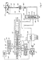
- Fig. 1 shows a multiplexed hydraulic control system exemplifying the principles of the present invention.
- the system includes a multiplexer generally indicated at 20 having a modulated hydraulic input 21 adapted to produce hydraulic flow rates which are distributed by the multiplexer 20 to a plurality of channels 22.
- the multiplexer 20 in the embodiment illustrated in Fig. 1 includes a hydraulic cylinder 25 having a reciprocatable operator 26 therein adapted for reciprocation between a pair of end points defined by ports 27, 28. It will be appreciated upon an understanding of the present disclosure that end points are not intended to be restricted to physical absolute limit of travel points of the hydraulic cylinder, but are simply intended to mean the positions associated with the end serviceable ports in the multiplexer.
- hydraulic oscillator means shown herein as including a double-acting cylinder 30, is provided for driving the multiplexer 25 to connect the modulated input 21 to each of the output channels 22 in a predetermined sequence.
- the double-acting cylinder is associated with driving means 31 for causing the cylinder to reciprocate and connecting means 72 for connecting the reciprocating cylinder 30 to the multiplexer 25.
- the driving means 31 provides hydraulic fluid to the double-acting cylinder 30 causing it to oscillate from end to end of its travel, and the connecting means 72 thereby causes the multiplexer 25 to similarly oscillate from end to end of its travel, thereby sequentially connecting the hydraulic input from modulated source 21 to the output ports 22 in turn.
- a modulated source of hydraulic fluid 21 in the illustrated embodiment such modulated source being provided by a torque motor 32 having an electrical input connection or bus 33 coupled to a controlling microprocessor 34.
- the microprocessor 34 produces a series of signals on its output bus 33 which are in part determined by demand input signals 35 coupled to the microprocessor 34 by external equipment, and in part determined by feedback signals relating to actuator positions to be described below.
- the bus 33 represents a time division multiplexed bus which is coupled to the torque motor 32 for controlling the hydraulic flow from source PC or sump PB through an output port 36 which in turn is coupled to the multiplexer as an input.
- a spool 37 in the control valve 38 will cause the connection of the hydraulic source PC or hydraulic sump PB to the outlet port 36, with the degree of opening of the valve and thus the rate of flow through the valve being dependent upon the magnitude of the signal applied to the torque motor 32.
- the signals applied to the torque motor 32 by way of the bus 33 are representative of the desired positions of the multiplicity of actuators controlled by the multiplexed control system, and the multiplexer 20 serves to couple the signal of appropriate hydraulic magnitude produced by the modulator 21 to the appropriate output channel 22.
- the output connections for one of the channels, namely, the channel connected to output port 41, is illustrated as including a second stage valve 50 having a spool 51 positioned in response to flow rate from the multiplexer valve, and having an outlet port 52 which connects a hydraulic actuator 53 to either the hydraulic source PC or hydraulic sump PB in dependence on the position of the spool 51.
- Feedback means 56 is coupled to the actuator 55 for providing an indication of the actuator position, and also for providing an indication of rate of movement of the actuator which is useful in stabilizing the control system, as will be described below.
- the second stage valve, actuator, and feedback elements associated with the output port 41 are replicated with respect to each of the other output ports and that therefore the modulated fluid source 21 is coupled to appropriate ones of the output channels for controlling the rate of movement and position of the hydraulic actuators (such as actuator 53) in the respective output channels.
- the embodiment illustrated in Fig. 1 demonstrates a first form of hydraulic oscillator means, which includes a hydraulically reversible double-acting cylinder 30 for controlling the position of the multiplexer valve 20.
- the double-acting cylinder 30 has a pair of inputs 57, 58 controllably supplied with hydraulic fluid by driving means 31 which include oscillator control valve 59.
- the oscillator control valve 59 in turn, in the Fig. 1 embodiment, has a position which is controlled by the multiplexer 20.
- the oscillator control valve 59 has the hydraulic source PC and hydraulic sump PB connected to the input ports thereof, and has a pair of output ports 60, 61 coupled to the respective ends of the double-acting hydraulic cylinder 30.
- the control valve 59 When the control valve 59 is positioned in its right-hand operating position as shown in Fig. 1, the hydraulic source PC is connected through the output port 61 to the left-hand chamber of the cylinder 30, the hydraulic sump PB is connected through the output port 60 to the right-hand chamber of the hydraulic cylinder 30, and thereby the hydraulic actuator is driven from the left to the right as illustrated by the solid arrow in Fig. 1.
- a mechanical connection 72 is provided between the hydraulic oscillator 30 and the multiplexer 20 such that as the hydraulic oscillator 30 oscillates, the mechanical connection causes the multiplexer 20 to also oscillate, causing the sequential coupling of the inlet 40 to individual ones of the output ports 27, 41, 42, 43, 28, 43, etc.
- the modulated flow produced in the control channel as a result of signals applied to the torque motor 32 are coupled through the multiplexer to the appropriate second stage valves which control the rate of movement of the output actuators 53 and ultimately the final positions thereof.
- the microprocessor 34 has available to it signals from the actuator transducers 56 (which indicate the actual actuator positions as well as rates of movement), and also has available to it signals from a position sensor 65 associated with the multiplexer 20 which indicates the identity of the channel being serviced at that point in time, such that the modulating signals on the bus 33 are coordinated with the position of the multiplexer 20.
- the embodiments of the invention share the feature of a reciprocatable hydraulically driven multiplexer (having substantial force margins) for selecting the individual channels, but differ in the manner in which the direction and rate of movement of the multiplexer is controlled.
- the multiplexer control is also hydraulic, including the hydraulically operable oscillator control valve 31 which feeds the double-acting cylinder 30 to translate a piston 70 within a cylinder 71 and, by means of the mechanical connection 72, to thereby translate the multiplexer 20 to sequentially connect the single inlet with individual ones of the output ports.
- means are provided for interconnecting selected ones of the hydraulic outputs, particularly the end channels 27, 28 in the illustrated embodiment, with the oscillator control valve 31 for controlling the direction and rate of movement of the multiplexer 20.
- the end ports 27, 28 are connected to the oscillator control valve 59 for causing the reversal of multiplexer movement as the multiplexer 20 reaches its end positions.
- the modulated hydraulic flow introduced into the multiplexer at the input 40 is coupled to the output 28 which in turn is coupled to a chamber 75 of the oscillator control valve 59.
- the torque motor 32 is driven to connect hydraulic sump PB to the modulator output port 36.
- fluid is drained from the control chamber 75 and the spool moves from the right-hand operating position illustrated in Fig.
- the microprocessor 34 drives the torque motor 32 in such a way to couple the high pressure source PC through the output 36 of the modulating valve 21, thereby directing fluid flow into the control chamber 75 of the oscillator control valve 59, and returning that valve to its right-hand operating position to again reverse the direction of multiplexer travel from left to right as illustrated in the drawing.
- the magnitude of the signal applied to the torque motor 32 by the microprocessor 34 at the time of reversing the oscillator control valve 59 determines the amount of fluid pumped into or removed from the control chamber 75 and thus the degree of opening of the oscillator control valve 59.
- the microprocessor 34 by this mechanism has direct control on the rate of multiplexer translation and thus the timing of the multiplexed sequencing between the output ports.
- the invention encompasses multiplexers other than the linear cylinder illustrated in Fig. 1, so long as the multiplexers are driven by hydraulic oscillators.
- a rotary multiple output valve as a multiplexer to sequentially connect a single input to individual outputs.
- Such a drive can be by way of the linear oscillator of Fig. 1 with a modified connecting means linking the oscillator driver and the multiplexer, the modifying connecting means serving to provide a linear to rotary translation.
- Such modified connecting means can, for example, be in the form of a pawl and ratchet drive or a gear and rack arrangement which serves to control the position of a rotary multiplexer in dependence on the linear position of the driving means.
- a rotary hydraulic oscillator can also be utilized.
- the first embodiment of the present invention fulfills the objects thereof by providing a modulated source of hydraulic fluid 21 which is coupled individually and selectively to a plurality of channels 22 by means of a multiplexer valve 20 driven by a hydraulic oscillator.
- the multiplexer valve is preferably of the type which has a reciprocatable spool having an inlet port 40 and a plurality of outlet ports 41-43 to sequentially couple the modulated hydraulic source to the various channels for controlling the appropriate second stage valves 50, coupled actuators 53, and feedback means 56.
- feedback means 65 are provided for detecting the position of the multiplexer 20 and providing a signal on a line 66 to the microprocessor 34.
- the microprocessor 34 senses the position of the multiplexer operator, and in response thereto modulates the input to the torque motor 32 in accordance with the electrical control signal corresponding to the output port of the channel then connected to the output of the multiplexer.
- all that is needed to drive the multiplexed control system is an electrical signal coupled to the torque motor 32 along with position signals derived from the multiplexer for signalling the microprocessor 34 of the channel then being serviced, so that the microprocessor 34 can coordinate the production of the appropriate modulated hydraulic signal while such modulated signal is being coupled to the selected channel.
- the microprocessor 34 produces a time division multiplexed series of signals for coupling onto the bus 33 for controlling the magnitude of the multiplexed hydraulic signal which is then distributed by the multiplexer 20.
- the microprocessor 34 responds to a plurality of electrical control signals which are coupled to it on demand inputs 35 and to feedback signals from the actuators 53 produced by feedback means 56 which signal the microprocessor 34 as to the actual position of the actuator 53 and the rate of travel of the actuator when the actuator is moving. Since the modulated flow produced by the modulator 21 is integrated by the second stage valve 50, and the flow which the second stage valve 50 produces is integrated by the actuator 53, means must be provided for stabilizing the control loop which contains two serially connected integrators.
- the rate feedback provided by feedback means 56 is important in stabilizing such a system as has been described more completely in copending Leeson et al. U.S. application U.S. Serial No. 306,842. That application describes both the feedback means and additional details of the control circuitry and, to the extent necessary, the specification of such application is incorporated herein by reference.
- Fig. 2 illustrates an embodiment of the invention similar to that of Fig. 1 but in which the oscillation of the control system is reversed by mechanical means responsive to the position of the multiplexing valve. More particularly, there is shown a multiplexer valve 100 which, as in the previous embodiment, is driven by a double-acting hydraulic cylinder 101 which is driven to oscillate between a pair of end positions.
- the input for the multiplexer is derived from an electrically actuated hydraulic modulator 102 which is responsive to electrical signals on a time division multiplexed bus 103 for controlling the flow rate through a valve 104, the flow rate serving as an input 105 to the multiplexing valve 100.
- the multiplexing valve 100 has a plurality of output ports 110-1 through 110-5 which are connected to associated channels including second stage valves such as the second stage valve 51 connected to output port 110-2.
- second stage valve 51 drives a hydraulic actuator 53 which has feedback means 56 for signalling position information to the microprocessor 134.
- a signal for purposes of controlling the direction of multiplexer travel, and for reversing such direction, means are provided for coupling a signal, in the illustrated embodiment a mechanical signal, between the multiplexer means and its multiplexer control valve 120.
- a link 109 is provided which is engaged by stop means 111, 112, depending on which limit of multiplexer travel is then being reached, to deflect link 109 in the direction of movement of the engaging stop means 111 or 112.
- the mechanical signal derived from the oscillating multiplexer serves to signal the oscillator control valve 120 to drive its spool 121 either to the left or to the right depending upon the direction of movement of the reciprocating actuator 106 in the multiplexer means 100.
- the multiplexer control valve 120 would be in its left-hand operating position as illustrated in Fig. 2 in order to drive the multiplexer in the stated direction.
- Fluid flow for driving the multiplexer in the right-hand direction is by way of the multiplexer control valve 120, particularly the high pressure hydraulic source PC is coupled through an outlet port 123 to the left-hand chamber 125 of cylinder 101 and sump PB is coupled through outlet port 122 of the valve 120 to the right-hand chamber 124 of the double-acting cylinder 101.
- the multiplexer continues it rightward travel as illustrated by the solid line arrow, it completes the servicing of output ports 110-3, 110-4 and 110-5 following which the stop means 111 engages the control link 109, shifting the spool 121 in the multiplexer control valve 120 to the right.
- the ports 122 and 123 are initially closed then opened to the opposite pressures, outlet port 122 being opened to hydraulic source and output port 123 to hydraulic sump to reverse the direction of multiplexer travel from right to left as illustrated by the dashed arrow.
- the control valve 120 includes hydraulic feedback means for assuring that the translation of the spool 121 which is initiated by engagement of stop means 111 with control link 109 is completed and the spool 121 is fully translated to one of its two operating positions.
- the valve 120 includes a pair of feedback connections 126, 127 operated by the same lands which control the output ports 122, 123.
- the lands open left-hand passage 126 to hydraulic source PC and the right-hand passage 127 to hydraulic sump PB, imposing source pressure on the left-hand end of the spool 121 and sump on its right-hand end, fully translating the spool to the right until it engages a stop member 128.
- the multiplexer 100 also includes feedback means 116 for providing a signal to the microprocessor 134 indicating which channel the microprocessor is servicing so that the appropriate electrical modulating signal can be coupled to the TDM bus 103. It will be appreciated that the position sensor 116 can be utilized in place of the stop members 111, 112 for providing an electrical signal operable on a solenoid or the like for translating the link member 109 to initiate a multiplexer reversal.
- Fig. 3 illustrates a slightly modified embodiment of the invention in which, at the expense of slight additional complexity in the multiplexer control valve 150, the hydraulic multiplexing system is provided the ability to sequence the output channels in a repeating sequence from 1 through n.
- the channels were sequenced from 1 through n and then from n through 1 following which the sequence repeated, thus producing dead times between cycling of particular channels which were different depending on whether the multiplexer was traveling in one direction or the other.
- the dead time between cycling of any particular channel remains the same, and the channels are always sequenced from 1 through n, and the sequence again begun at 1.
- each of the output channels 1-n includes a second stage valve 51 driving a hydraulic actuator 53 which has feedback means 57 producing a signal which is coupled back to the microprocessor 134.
- the modulated source is coupled to the multiplexer by way of the multiplexer control valve 150.
- the operation of control valve 150 is identical to that of control valve 120 of Fig. 2 and the same reference numerals have been used for the corresponding elements.
- the hydraulic valve 150 controls the application of the modulated hydraulic signal produced by source 102 to a pair of inputs 152, 153 of the multiplexer generally indicated at 154. It is seen that the output port 105 of the hydraulic source 102 is coupled to a pair of input ports 155, 156 of the multiplexer control valve 150. In the illustrated left-hand operating position of the control valve 150, the hydraulic source 102 is coupled via port 155 to the multiplexer input 152 which input services the ports 1, 2 and 3. Thus, as the valve actuator 158 is translated to the right as indicated by the solid line arrow, the ports 1, 2 and 3 will be activated in sequence to pass modulated hydraulic flow through the multiplexer input port 152 to those output ports.
- the multiplexer will reach its rightmost end of travel whereupon stop member 111 will engage control link 109 and shift the spool 151 of the control valve 150 to its right-hand operating position.
- hydraulic feedback will assure the spool travels to engage the mechanical stop, and flow to the double-acting cylinder 101 will be reversed to drive the cylinder and its connected multiplexer in the left-hand direction as indicated by the dashed arrow.
- translation of the spool 151 of the control valve 150 to the right-hand position will close the port 155 and open the port 156 to couple the modulated hydraulic source 102 to the second multiplexer input port 153.
- the actuator 154 will have the input 153 open to the outlet port which services channel 4, thereby coupling the modulated hydraulic source 102 to that channel. Further translation of the multiplexer in the left-hand direction as indicated by the dashed arrow will thereupon service the succeeding channels n-1 and n, following which the stop member 112 will engage the control link 109 to drive the spool to the left and re-initiate the sequence.
- Fig. 4 is functionally similar to Fig. 3 in that it produces a repeating sequence for servicing of the output ports from 1 through n.
- the means for accomplishing such repeating sequence is somewhat different than the embodiment of Fig. 3.
- Such difference is primarily in the multiplexing valve 170 which includes not only an operator 171 for sequentially activating the ports, but a second two-position slidable sleeve 172 which assists in achieving the repeating 1 through n sequence.
- the system of Fig. 4 is identical to that of Fig. 2 and the same reference numerals have been used for similar elements.
- the output 105 of the hydraulic modulator 102 is coupled to a manifold 175 within the multiplexer which is associated with the sleeve 172. It is seen that the sleeve 172 for a six input manifold 175 has only three passages 177-179 for interconnecting the input manifold 175 with the multiplexer operator 171. It will be seen that in the illustrated condition the modulated hydraulic flow produced at the output 105 of the modulator 102 is coupled through the passage 178 to output port No. 2. As the multiplexer continues to sequence to the right under the assumed conditions, the port No.
- the ports 4, n-1 and n will be actuated in sequence.
- the multiplexer will have reached its leftmost condition in which the stop 112 will engage the control link 109 to shift the valve 120, and a further stop 112 will engage the sleeve means 172 to return it to the solid line position of Fig. 4 ready to commence a further sequence of cycling the output ports from 1 through n.
- Fig. 5 illustrates a system which is similar to those illustrated in the earlier drawings in its use of a hydraulic oscillator for driving the multiplexer, the oscillator including a double-acting cylinder 101 driven by an oscillator control valve 180. Since it is only the control valve 180 and the elements which drive it which differ from the system of Fig. 2, the reference numerals on the remaining elements of Fig. 5 are the same as used in Fig. 2, and those elements will not be further described here.
- control valve 180 includes a pair of chambers 181, 182 disposed in a valve body 183 at either end of a displaceable spool 184.
- electrical means generally indicated at 185 are associated with the control valve 180 for controlling fluid flow into chambers 181, 182 and thereby the direction and rate of movement of the double-acting cylinder 101.
- control means 185 is configured as an electrically responsive jet pipe including a jet pipe receiver 186 having a pair of channels 187, 188 coupled between the outlet 189 of the jet pipe 190 and the chambers 181, 182 of the valve 180.
- the pressure in chambers 181 and 182 will be controlled. For example, if the jet pipe 190 is deflected to the left, there will be a greater pressure in chamber 181 than in chamber 182, and the spool 184 will be deflected downwardly, connecting the hydraulic source PC to the left-hand side of the piston in double-acting cylinder 101 and sump to the right-hand side.
- the double-acting cylinder 101 will drive its piston to the right, connecting the multiplexer input 105 to the output ports 110-1 through 110-5 in that sequence.
- feedback means 116 produces a signal representative of the position of the multiplexer and couples such signal to the microprocessor 134.
- the microprocessor 134 determines that the multiplexer has reached its rightmost limit, it will produce a signal on an output line 192 which controls the electrical actuator 193 of the electrically responsive assembly 185.
- the actuator 193 will then deflect the jet pipe 190 to the right, producing a higher pressure in chamber 182 than in 181, raising the spool 184 and thus reversing the direction of travel of the double-acting cylinder 101 with connected multiplexer 100.
- the magnitude of the electrical signal coupled by the microprocessor 134 to the electrical actuator 193 will determine the pressure differential between the chambers 181, 182 and thus the rate of travel of the multiplexer. Since the microprocessor 134 can adjust the magnitude of the signal applied to the actuator 193, in dependence upon sensed conditions, the Fig. 5 embodiment demonstrates the advantage of a sequentially operated multiplexer with a travel rate which can be varied during operation to satisfy operating conditions then being encountered.
- Figs. 6 and 7 illustrate further embodiments of the present invention in which, in contrast to the previous figures where the hydraulic oscillator was in the form of a single multiplexing cylinder driven first in one direction and then in the other by an oscillator control valve, the hydraulic oscillator of Figs. 6 and 7 is configured as a pair of hydraulic sequencers cross-coupled for oscillation.
- the hydraulic oscillator of Figs. 6 and 7 is configured as a pair of hydraulic sequencers cross-coupled for oscillation.
- sequencers 301, 302 having cross-coupled connections generally indicated at 303 connecting the hydraulic source PC and sump PB between the sequencers in such a way as to cause the sequencers to oscillate.
- a modulated source of hydraulic fluid 305 is provided as an input to the pair of sequencers and the outlet ports are illustrated at 307, demonstrating that the fluid passed through the sequencers in dependence upon the electrical signals provided to the modulator 305 are distributed to the channels connected to output ports 1-n. It is noted that Figs. 6 and 7 omit certain elements which are peripheral to the multiplexer but which are the same as those illustrated in the prior embodiments.
- a microprocessor for producing electrical signals to control the modulator 305 for producing appropriately modulated hydraulic signals for the respective channels
- feedback means on the sequencers for producing signals indicative of the actuated channels so that the microprocessor can produce the appropriately modulated hydraulic signal for the selected channel
- the channel elements themselves including second stage valves, hydraulic actuators for positioning the elements to be controlled, and feedback means for signalling the microprocessor with position information for the actuators.
- the hydraulic oscilia- tor means utilizes the cross-coupled hydraulic connection 303 to cause the sequencers 310, 311 to operate in opposite directions, with one of the sequencers being stationary while the other is moving in one or the other of its directions.
- hydraulic flow from the port 320 passes through connection 321 to the lower chamber 322 of the sequencer 302 to drive such sequencer upwardly.
- the multiplexed output port 323 sequentially connects the modulated inlet at port 324 to output ports 6, then 5, then 4 (the illustrated position).
- a port 325 is opened to couple the high pressure source PC through a conduit 326 to the upper chamber 327 of the opposite sequencer 301.
- the actuator 328 of the sequencer 301 is driven downwardly, thus sequentially activating, by means of valve land 329 the output ports 1, 2, 3 in that order.
- the control port 330 is opened coupling the high pressure source PC by way of conduit 331 to the upper chamber 332 of sequencer 302, thereby causing the sequencer 302 to be driven in the downward direction.
- the sequencers operate in alternate fashion, first going down, then going up, with the dual sequencers operating in turn such that the modulated input signal provided by source 305 is multiplexed to the channels connected to ports 1-6.
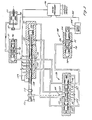
- Fig. 7 illustrates an alternative embodiment similar to Fig. 6 in that a pair of sequencers are utilized, but the pair is cross-coupled in such a way that the output channels are serviced in a continuing repeating sequence from 1 through n.
- a pair of cross-coupled sequencers generally indicated at 350, are provided having an input port 351 fed by a common modulator 352, and a plurality of output ports 355 which have flow controlled by the positions of the sequencers in a fashion similar to that illustrated in connection with Fig. 6.
- the embodiment of Fig. 7 uses a first sequencer 357 which serves to connect the modulated input produced by source 352 from the input port 351 to a series of output ports 361-363.
- the output ports are connected as inputs to the second sequencer 365, and the second sequencer 365 serves to connect the input as passed through the first sequencer individually to one of the output channels 1-6.
- the modulated pressure source coupled to inlet port 351 is coupled through the input manifold to intermediate output port 361, and thence by way of valve portion 367 to output port 3.
- the cross-coupled ports 303 are the same as illustrated in connection with Fig. 6 and will not be further described. Suffice it to note, however, that in the illustrated condition the lower sequencer 365 is at rest and the upper sequencer 357 is being driven to the left by way of hydraulic source coupled through port 370 and conduit 371 to the right chamber 372 of the sequencer 357.
- a port 373 is opened to couple the hydraulic source by way of conduit 374 to the left chamber 375 of lower sequencer 365, thereby shifting the lower sequencer to the right, aligning ports 367, 367 and 367" with output ports 4, 5 and 6, respectively.
- the hydraulic source is coupled via a port 376 and conduit 377 to the left chamber 378 of the upper sequencer 357, causing that sequencer to move to the right, sequentially activating ports 361, 362 and 363.
- the hydraulic ports 4, 5 and 6 are thereupon actuated in sequence.
- a multiplexed hydraulic control system which shares a single modulated source of hydraulic fluid among a plurality of output channels.
- the output channels are selected in a predetermined sequence by a multiplexing hydraulic valve which in turn is driven by a hydraulic oscillator.
- the multiplexing valve may be part of the hydraulic oscillator or simply driven by the hydraulic oscillator, but in either case, the oscillator is the driving means for causing the multiplexer to sequence.
- the substantial force margins provided by the hydraulic oscillator as contrasted with dedicated electrical actuators, provide a substantial margin of reserve actuating force for the multiplexer in systems where such a safety factor is needed or desired.
Landscapes
- Engineering & Computer Science (AREA)
- Physics & Mathematics (AREA)
- General Physics & Mathematics (AREA)
- Automation & Control Theory (AREA)
- Human Computer Interaction (AREA)
- Manufacturing & Machinery (AREA)
- Servomotors (AREA)
- Control Of Throttle Valves Provided In The Intake System Or In The Exhaust System (AREA)
Applications Claiming Priority (2)
| Application Number | Priority Date | Filing Date | Title |
|---|---|---|---|
| US387177 | 1989-07-28 | ||
| US07/387,177 US5048394A (en) | 1989-07-28 | 1989-07-28 | Multiplexed hydraulic control system with oscillator for multiplexer drive |
Publications (2)
| Publication Number | Publication Date |
|---|---|
| EP0410812A2 true EP0410812A2 (fr) | 1991-01-30 |
| EP0410812A3 EP0410812A3 (en) | 1991-06-19 |
Family
ID=23528809
Family Applications (1)
| Application Number | Title | Priority Date | Filing Date |
|---|---|---|---|
| EP19900308304 Withdrawn EP0410812A3 (en) | 1989-07-28 | 1990-07-27 | Multiplexed hydraulic control system |
Country Status (3)
| Country | Link |
|---|---|
| US (1) | US5048394A (fr) |
| EP (1) | EP0410812A3 (fr) |
| JP (1) | JPH0389002A (fr) |
Cited By (1)
| Publication number | Priority date | Publication date | Assignee | Title |
|---|---|---|---|---|
| WO1996012991A1 (fr) * | 1994-10-21 | 1996-05-02 | United Technologies Corporation | Reseau de commande hydraulique de multiplexage avec vannes de verrouillage |
Families Citing this family (14)
| Publication number | Priority date | Publication date | Assignee | Title |
|---|---|---|---|---|
| US5318065A (en) * | 1992-11-20 | 1994-06-07 | Ransburg Corporation | Color valve multiplexer |
| US5546988A (en) * | 1994-09-23 | 1996-08-20 | Alliedsignal Inc. | Servo multiplexing system |
| FR2726344B1 (fr) * | 1994-10-31 | 1998-02-20 | Hr Textron Inc | Servovalves hydrauliques a multiplexage |
| US5533935A (en) * | 1994-12-06 | 1996-07-09 | Kast; Howard B. | Toy motion simulator |
| US5787786A (en) * | 1996-05-09 | 1998-08-04 | Sauer-Sundstrand - Control Concepts | Dual hydraulic oscillator for the reciprocating cutter of an agricultural machine |
| US5922032A (en) * | 1997-12-16 | 1999-07-13 | United Technologies Corporation | Controller and method of controlling a hydraulic control network with latching valve |
| US6158208A (en) * | 1998-12-04 | 2000-12-12 | Woodward Governor Company | Multiplexed fluid control system with pressure transducer feedback |
| US6186045B1 (en) | 1998-12-07 | 2001-02-13 | Woodward Governor Company | Latching valve and a multiplexed hydraulic control system utilizing same |
| US5996464A (en) * | 1998-12-07 | 1999-12-07 | Woodward Governor Company | Fail safe valve and multiplexed fluid control systems incorporating the same |
| US6196248B1 (en) | 1999-08-03 | 2001-03-06 | General Electric Company | Fuel flow control system |
| US7658059B2 (en) * | 2007-06-04 | 2010-02-09 | Crary Industries, Inc. | Synchronous drive for split sickle bars on harvester header |
| GB0722669D0 (en) * | 2007-11-20 | 2007-12-27 | Goodrich Control Sys Ltd | Fuel staging system |
| US10113564B2 (en) | 2016-12-23 | 2018-10-30 | Robert Bosch Gmbh | Hydraulic system and method of operating the same |
| DE102023133936A1 (de) * | 2023-12-05 | 2025-06-05 | Liebherr-Aerospace Lindenberg Gmbh | Steuereinheit, System und Verfahren |
Family Cites Families (19)
| Publication number | Priority date | Publication date | Assignee | Title |
|---|---|---|---|---|
| DE1199619B (de) * | 1959-05-16 | 1965-08-26 | Ludwig Ehrhardt | Hydraulische Folgesteuereinrichtung fuer die Steuerung mehrerer Arbeitsmotoren |
| US3645141A (en) * | 1969-06-27 | 1972-02-29 | Walter J Moore | Random-access pressure multiplexer valving arrangement and system |
| DE2725410C2 (de) * | 1977-06-04 | 1983-09-01 | Bodenseewerk Perkin-Elmer & Co GmbH, 7770 Überlingen | Vorrichtung zur Steuerung einer Druckmittelströmung |
| US4271867A (en) * | 1978-01-30 | 1981-06-09 | Fmc Corporation | Method and apparatus for hydraulically controlling subsea well equipment |
| EP0037746B1 (fr) * | 1979-07-21 | 1986-04-09 | Fmc Corporation | Dispositif de commande rotatif |
| US4325127A (en) * | 1979-11-30 | 1982-04-13 | Emery Major | Flow meter system |
| US4664136A (en) * | 1981-10-01 | 1987-05-12 | South Bend Controls Inc. | Pressure regulating transducer |
| JPS59117903A (ja) * | 1982-12-23 | 1984-07-07 | S G:Kk | 流体圧シリンダを用いた多軸制御装置 |
| JPS608501A (ja) * | 1983-06-25 | 1985-01-17 | Toyota Motor Corp | 油圧制御装置 |
| US4805515A (en) * | 1983-11-18 | 1989-02-21 | General Electric Company | Fail-safe servovalve system |
| DE3347000A1 (de) * | 1983-12-24 | 1985-07-04 | Robert Bosch Gmbh, 7000 Stuttgart | Elektrohydraulische einrichtung zur steuerung eines doppeltwirkenden hydromotors |
| US4549578A (en) * | 1984-03-21 | 1985-10-29 | Exxon Production Research Co. | Coded fluid control system |
| DE3435952A1 (de) * | 1984-09-29 | 1986-04-10 | Gewerkschaft Eisenhütte Westfalia, 4670 Lünen | Ventilvorrichtung fuer hydraulische ausbausystem u.dgl. |
| US4712173A (en) * | 1984-10-01 | 1987-12-08 | Yamatake Honeywell | Multicontrol process control system |
| GB2174824B (en) * | 1985-05-08 | 1989-07-19 | Rolls Royce Plc | Control systems for gas turbine engines |
| US4744218A (en) * | 1986-04-08 | 1988-05-17 | Edwards Thomas L | Power transmission |
| US4838145A (en) * | 1987-06-18 | 1989-06-13 | The United States Of America As Represented By The Secretary Of Commerce | Multiple actuator hydraulic system and rotary control valve therefor |
| CN1017276B (zh) * | 1988-02-17 | 1992-07-01 | 通用电气公司 | 液体多通道转换器 |
| US4913032A (en) * | 1988-12-19 | 1990-04-03 | Woodward Governor Company | Multiplexed hydraulic control systems |
-
1989
- 1989-07-28 US US07/387,177 patent/US5048394A/en not_active Expired - Lifetime
-
1990
- 1990-07-27 EP EP19900308304 patent/EP0410812A3/en not_active Withdrawn
- 1990-07-30 JP JP2202333A patent/JPH0389002A/ja active Pending
Cited By (1)
| Publication number | Priority date | Publication date | Assignee | Title |
|---|---|---|---|---|
| WO1996012991A1 (fr) * | 1994-10-21 | 1996-05-02 | United Technologies Corporation | Reseau de commande hydraulique de multiplexage avec vannes de verrouillage |
Also Published As
| Publication number | Publication date |
|---|---|
| US5048394A (en) | 1991-09-17 |
| JPH0389002A (ja) | 1991-04-15 |
| EP0410812A3 (en) | 1991-06-19 |
Similar Documents
| Publication | Publication Date | Title |
|---|---|---|
| US5048394A (en) | Multiplexed hydraulic control system with oscillator for multiplexer drive | |
| US4913809A (en) | Concentrating apparatus with reverse osmosis membrane | |
| US6205780B1 (en) | Low-loss drive system for a plurality of hydraulic actuators | |
| EP0410811B1 (fr) | Système de commande hydraulique | |
| EP1167778B1 (fr) | Servovalve rotative et dispositif asservi hydraulique de presse a decouper utilisant cette servovalve rotative | |
| KR910003223A (ko) | 주행식 건설기계의 유압펌프 제어회로 | |
| EP0375372B1 (fr) | Système de commande hydraulique avec multiplexage | |
| KR970702452A (ko) | 펄스 폭 변조 비율제어기를 구비하는 연속적인 가변 유체정역학적 트랜스미션(continuously variable hydrostatic transmission including a pulse width modulation ratio controller) | |
| US5088383A (en) | Multiplexed hydraulic control system with multiplexing valve having planar port array | |
| EP0437111B1 (fr) | Système de commande hydraulique multiplexée | |
| RU2134363C1 (ru) | Гидравлическое золотниковое распределительное устройство | |
| US4463656A (en) | Pneumatic motor drive | |
| CA2281066A1 (fr) | Systeme de conduites d'eau a servomoteurs a piston avec detection autonome hydromecanique de pannes | |
| US2237871A (en) | Stoker drive | |
| US6116143A (en) | Controller for a fluid cylinder | |
| EP0644336A1 (fr) | Vanne de multiplexage | |
| DE3773720D1 (de) | Antriebe "steuerung fuer hydraulikzylinder als antriebe fuer kolbenpumpen". | |
| SU1224469A1 (ru) | Гидропривод | |
| WO1986000956A1 (fr) | Unite d'entrainement motorisee et systeme de regulation pour celle-ci | |
| EP4635710A1 (fr) | Système de régulation d'un débit injecté de matière fondue | |
| RU2147346C1 (ru) | Гидропривод синхронизации валов гидромоторов неполноповоротных | |
| USRE25700E (en) | Hydraulic control apparatus | |
| SU1611777A1 (ru) | Объединенна гидравлическа система рулевого управлени и дополнительного потребител дл транспортного средства | |
| SU885641A1 (ru) | Гидропривод | |
| SU1250741A1 (ru) | Система синхронизации движени гидроцилиндров |
Legal Events
| Date | Code | Title | Description |
|---|---|---|---|
| PUAI | Public reference made under article 153(3) epc to a published international application that has entered the european phase |
Free format text: ORIGINAL CODE: 0009012 |
|
| AK | Designated contracting states |
Kind code of ref document: A2 Designated state(s): DE FR GB IT SE |
|
| PUAL | Search report despatched |
Free format text: ORIGINAL CODE: 0009013 |
|
| RHK1 | Main classification (correction) |
Ipc: F15B 13/07 |
|
| AK | Designated contracting states |
Kind code of ref document: A3 Designated state(s): DE FR GB IT SE |
|
| 17P | Request for examination filed |
Effective date: 19911001 |
|
| 17Q | First examination report despatched |
Effective date: 19930405 |
|
| STAA | Information on the status of an ep patent application or granted ep patent |
Free format text: STATUS: THE APPLICATION IS DEEMED TO BE WITHDRAWN |
|
| 18D | Application deemed to be withdrawn |
Effective date: 19931113 |