EP0410905A1 - Verfahren zum Wiederanspinnen von aus Fasern bestehenden Kerngarnen, neuartiges durch dieses Verfahren verwirklichtes Wiederanspinnen und Maschine hierzu - Google Patents
Verfahren zum Wiederanspinnen von aus Fasern bestehenden Kerngarnen, neuartiges durch dieses Verfahren verwirklichtes Wiederanspinnen und Maschine hierzu Download PDFInfo
- Publication number
- EP0410905A1 EP0410905A1 EP90420346A EP90420346A EP0410905A1 EP 0410905 A1 EP0410905 A1 EP 0410905A1 EP 90420346 A EP90420346 A EP 90420346A EP 90420346 A EP90420346 A EP 90420346A EP 0410905 A1 EP0410905 A1 EP 0410905A1
- Authority
- EP
- European Patent Office
- Prior art keywords
- fibers
- wire
- core
- condenser
- yarn
- Prior art date
- Legal status (The legal status is an assumption and is not a legal conclusion. Google has not performed a legal analysis and makes no representation as to the accuracy of the status listed.)
- Withdrawn
Links
- 238000009987 spinning Methods 0.000 title claims abstract description 60
- 238000000034 method Methods 0.000 title claims abstract description 48
- 239000000835 fiber Substances 0.000 claims abstract description 99
- 238000004804 winding Methods 0.000 claims abstract description 20
- 238000003860 storage Methods 0.000 claims abstract description 10
- 238000009826 distribution Methods 0.000 claims abstract description 7
- 238000000605 extraction Methods 0.000 claims abstract description 4
- 230000008569 process Effects 0.000 claims description 20
- 238000011084 recovery Methods 0.000 claims description 20
- 238000004519 manufacturing process Methods 0.000 claims description 12
- 238000012545 processing Methods 0.000 claims description 11
- 239000002699 waste material Substances 0.000 claims description 11
- 238000009434 installation Methods 0.000 claims description 10
- 230000000903 blocking effect Effects 0.000 claims description 9
- 238000000151 deposition Methods 0.000 claims description 8
- 238000011144 upstream manufacturing Methods 0.000 claims description 8
- 238000006073 displacement reaction Methods 0.000 claims description 7
- 230000008021 deposition Effects 0.000 claims description 5
- 230000033001 locomotion Effects 0.000 claims description 5
- 125000006850 spacer group Chemical group 0.000 claims description 5
- 230000000977 initiatory effect Effects 0.000 claims description 4
- 238000005299 abrasion Methods 0.000 claims description 3
- 238000007670 refining Methods 0.000 claims description 3
- 239000007858 starting material Substances 0.000 claims description 3
- 230000009471 action Effects 0.000 claims description 2
- 238000005070 sampling Methods 0.000 claims description 2
- 230000006978 adaptation Effects 0.000 description 8
- 230000033458 reproduction Effects 0.000 description 6
- 230000015572 biosynthetic process Effects 0.000 description 5
- 230000007547 defect Effects 0.000 description 5
- 238000001514 detection method Methods 0.000 description 4
- 238000010586 diagram Methods 0.000 description 3
- 238000006677 Appel reaction Methods 0.000 description 2
- 241000135309 Processus Species 0.000 description 2
- 241001249696 Senna alexandrina Species 0.000 description 2
- 241001080024 Telles Species 0.000 description 2
- 238000005520 cutting process Methods 0.000 description 2
- 230000002093 peripheral effect Effects 0.000 description 2
- 230000000750 progressive effect Effects 0.000 description 2
- 229920000742 Cotton Polymers 0.000 description 1
- 238000004026 adhesive bonding Methods 0.000 description 1
- 238000000429 assembly Methods 0.000 description 1
- 230000000712 assembly Effects 0.000 description 1
- 230000008859 change Effects 0.000 description 1
- 239000000470 constituent Substances 0.000 description 1
- 238000013461 design Methods 0.000 description 1
- 230000006866 deterioration Effects 0.000 description 1
- 235000021183 entrée Nutrition 0.000 description 1
- 230000004907 flux Effects 0.000 description 1
- 235000013305 food Nutrition 0.000 description 1
- 230000006872 improvement Effects 0.000 description 1
- 238000005304 joining Methods 0.000 description 1
- 239000000463 material Substances 0.000 description 1
- 230000004048 modification Effects 0.000 description 1
- 238000012986 modification Methods 0.000 description 1
- 210000000056 organ Anatomy 0.000 description 1
- 230000006641 stabilisation Effects 0.000 description 1
- 238000011105 stabilization Methods 0.000 description 1
- 239000004753 textile Substances 0.000 description 1
- 238000012546 transfer Methods 0.000 description 1
Images







Classifications
-
- D—TEXTILES; PAPER
- D01—NATURAL OR MAN-MADE THREADS OR FIBRES; SPINNING
- D01H—SPINNING OR TWISTING
- D01H15/00—Piecing arrangements ; Automatic end-finding, e.g. by suction and reverse package rotation; Devices for temporarily storing yarn during piecing
Definitions
- the present invention relates to a process making it possible to produce and re-attach yarns of fibers comprising an internal core, yarns which in the following description will be designated by the expression "core yarns"; it also relates to a new type of piecing made using such a method as well as an improved spinning machine enabling it to be implemented.
- the most common is to introduce a multifilament core inside a wick, during the last spinning operation, that is to say on the continuous spinning, said core being introduced upstream of the last pair of wick stretching rollers.
- European patent no. 0206 956 (corresponding to patent US-A-4,757,680) describes an improvement made to such a technique and which in particular makes it possible to automate such machines and to perform in a simple, efficient and precise manner, the recovery operation after breakage of a wire or during any other intervention, or even when replacing a full spool with an empty winding support.
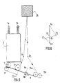
- spinning installations of the aforementioned type comprise, as illustrated in FIGS. 1, 2, 2a and 2b annexed (figures which are reproductions of FIGS. 6 to 9 of the aforementioned European patent no. 0206 956), a plurality of identical working positions arranged side by side on a support frame.
- Each working position essentially comprises, arranged between a source of fiber supply and a set for receiving the finished yarn (elements not shown in FIGS. 1 to 2b for simplification purposes), a treatment set proper, disposed at the outlet.
- a drawing system (designated by the general reference (E)), making it possible to treat two strands of fibers (1a, 1b), the fibers (1a) being intended to form the covering of the yarn while the fibers (1b ) are intended to form the soul.
- Such a spinning block consists essentially of a guide surface (4) or condenser element in the form of a hollow rotary cylinder pierced over its entire periphery with orifices (5). The rotary cylinder is subjected to the action of a suction source.
- a false twist pin (6) is arranged downstream of this condenser guide (4). Upstream of the condenser guide (4), is arranged a second condenser element (7) of a design similar to the condenser (4) and which is associated with a movable roller (8). Thanks to such an assembly, taking into account the twist communicated by the spindle (6) which rises to the nip between the condenser (7) and the roller (8), it is formed using fibers (10 ) from the wick (1b) a core (11).
- the fibers (9) which come from the wick (1a) and which are delivered to the surface of the condenser (4) are deposited against the surface of the core wire (11) and, taking account of the displacement of the latter and of the twisting which goes up, are blocked around this soul forming, in a way a covering.
- the core (7) and cover (4) condensing elements not only ensure the transfer of the fibers from the outlet of the drawing system (E), but also a parallelization of the fibers. elementary (9,10) as well as an additional stretching function of their peripheral speed.
- By adjusting the peripheral speeds of said condensers (4,7) it is possible to modify the composition of the yarn obtained (modification of the proportion of the fibers constituting the core (11) relative to the covering fibers) as well as the final titer.
- the covering condenser element (element 4) and the core condenser element (element 7), the false twist spindle (6) and the yarn calling system (13) ( 14) formed are grouped on a common box designated by the general reference (15) in Figure 2 in the form of a compact assembly. Furthermore, on this box, between the outlet of the stretching system (2,3) and the surface of the condenser (4,7), are arranged separating elements (16,17,18) forming guide channels allowing channel the elementary fibers (9,10) of the wicks (1a, 1b) well, avoiding not only fiber losses, but also any disturbance between the two fibrous flows.
- the recovery and reattachment method according to the invention during a spinning operation on a machine making it possible to produce a yarn of core fibers is characterized in that it comprises the succession of the following operations: - sampling of a length of yarn previously formed from the winding support; - setting aside a length of wire thus taken from inside a storage assembly; - Introduction in the form of a stretched strand of part of the yarn thus set aside inside all of the members allowing the making of the core yarn; - restarting of the winding and clutch assembly of the bodies of the processing blocks, the fibers coming from the drawing system (E) being put into waste; - during the advance of the starter thread on the spinning members: .
- a surface abrasion device allowing a refinement of the end of the launching wire is provided and is implemented when the fibrous flow intended to form the core is initiated.
- the method according to the invention can be implemented both when it is desired to make a connection following a breakage of the wire (either accidental or caused to eliminate a defect) during its production, and possibly when the we want to restart the machine by replacing a full coil with an empty support tube, in which case the latter will then include a few meters of wire previously formed and wound around it.
- the rotary roller (8) and one of the call cylinders of the output deliverer (13), in the present case the call cylinder (13a), are projecting with respect to the other elements of the spinning block (core condenser, cover condenser and false twist spindle); furthermore, the core and cover condensers have a conical front face.
- the storage assembly for the wire reserve is preferably in the form of a suction tube associated with a mobile element, sliding inside the tube, thus making it possible not only to bring the wire to the inside the work plan, but also facilitating the removal of the wire stored inside the reserve and its introduction into the different elements of the processing block.
- the method according to the invention consists, during the reattachment operation (after a breakage or possibly when replacing a full coil with an empty support tube), at: - take a length of wire previously formed from the winding support (in the case where the process would be implemented when restarting the machine by replacing a full spool with an empty support, the latter will include a few meters of thread beforehand trained); store said thread thus taken inside the reserve arranged below the spinning plane between the first condenser and the false twist spindle, the path of the thread from the winding reel to the entry of the reserve being produced so that the portion of wire forms a loop surrounding the rotary roller associated with the core condenser, and the elongated roller of the call deliverer located downstream of the processing block; - Introduce a portion of yarn stretched between these two elongated elements, practically instantaneously inside each of the bodies of the spinning block, this introduction being carried out with the yarn running with its processing speed, starting by placing the yarn in reserve between the core condenser and its pressure roller
- the channels for guiding the fibrous fluxes of core and covering arranged between the outlet of the drawing system and the surface of the condensing elements of core and covering are associated with suction means allowing the waste to be put into the fibers during the preparatory phase for launching, this aspiration being eliminated, according to a programmed sequence and determined during the launching proper, so that the covering fibers are deposited on the recovery wire prior to the deposition of the fibers intended to form the core.
- Additional means can be provided to improve the quality of the piecing, such as for example means making it possible to refine the stimulus wire.
- a working position of a machine comprises a drawing system E, common to the two wicks of fibers (1a, 1b) intended to form the cover and the core of the wire respectively.
- This stretching system is preferably arranged vertically or substantially vertically on the machine frame.
- the spinning block proper is arranged, the various members of which are mounted on a support box not shown for simplification.
- This spinning block comprises, arranged immediately below the last pair of cylinders (2,3) of the stretching system E, a set of separating elements (16,17,18) forming guide channels (19, 20) for the fiber flows leaving the drawing system E.
- the elementary fiber flows (9, 10) forming the cover and core are not shown for simplicity.
- These separating elements (16, 17, 18) and the channels (19) which they define between them are constituted for example by a monobloc machined part which comes to wrap on a part of their periphery the condensing elements (4,7) of the fibers. of cover and soul.
- the entire spinning block is produced in a similar manner to the example illustrated in FIG. 5 of European patent no. 206956, if not, as will be seen in the following description, that the members that compose it are adapted to allow automation of the machine to perform the recovery operations.
- the feeding of the wicks of fibers to be treated (wicks 1a, 1b) and the extraction of the formed wire (14) at the outlet of the deliverer (13) are carried out in the opposite direction in a vertical or substantially vertical plane, while the path of the material inside the spinning block is produced either horizontally, or preferably in a plane slightly inclined in plane P known as the "spinning plane" which passes through the nip between the core condenser (7) and the roller (8), the point of tangency of the wire being formed on the surface of the condenser (4), between the two belts (6a, 6b) of the false twist spindle (6) and the point of contact of the wire with the roller (13a) of the output deliverer (13 ).
- the spinning plane is not a real flat surface, the wire coming slightly into contact with the cover condenser (4) and the surface of the belts (6).
- a storage assembly (20) for a reserve of wire length is arranged below the above-mentioned plane P.
- This storage assembly shown diagrammatically in FIG. 4 consists essentially of a suction tube (21) and is associated with a mobile assembly (22) called "launching cylinder" and which allows, as will be seen in the following description , during launching, the introduction of the yarn inside the different elements constituting the spinning block and, simultaneously, the extraction of the yarn stored inside said reserve.
- This mobile element (22) consists of a sliding tube inside the inlet end of the reserve (20).
- the torsion blocking roller (8) associated with the core condenser (7) as well as the roller (13a) of the output deliverer (13) have a length such that they overflow on the front compared to the other elements of the spinning block.
- the inlet faces of the condensers (7) and (4) are of conical shape and the false twist pin (6) is associated with a ramp (23) which, during the introduction of the wire, brings the latter against the upper belt (6a) of the spindle (6) in order to facilitate its positioning (see FIG. 8).
- each working position comprises, and this is shown only in FIG. 3, suction means (24.25) associated with each condenser (4.7) and which allow the fibers of the wicks (1a) to be disposed of. , 1b) until the normal operating process is implemented.
- Means for refining the stimulus wire can also be associated with the spinning block, these refining means being constituted by an abrasive surface (27) (see FIG. 3) disposed upstream of the nip between the condenser d 'core (7) and the roller (8), and which is constituted for example by a flexible strip.
- This element (27) not only makes it possible to refine the end of the recovery wire during the final phase of the process, and also prevents the free end of the recovery wire after cutting from forming a defect.
- FIGS. 6 and 7 During the stop sequence following a break, the following operations are carried out, illustrated diagrammatically in FIGS. 6 and 7: - after detection of breakage between the output deliverer (13) and the winding system designated by the general reference (25), detection carried out using any known element, the stretching arm (E) is opened as well as the spacing of the two belts (6a, 6b) of the false twist spindle (6) and this, very quickly in order to limit the fouling of the condensers (7,4) and the deterioration of the strips of the spindles; - After opening, the reel (25) of its drive system (26) is then raised or the drive system stops; this lifting is of the order of a few millimeters relative to the engine cylinder (26) and is carried out by means of a device making it possible to have a constant and identical spacing (e) whatever the diameter of the winding (25 ); this operation is carried out very quickly in order to avoid "burying" the end of the wire formed inside the coil (25); the reel being raised, the drawing
- the vacuum can be maintained inside each of the condensers (4,7). Furthermore, the torsion blocking roller (8) remains in abutment on the core condenser (7) as well as the pressure roller (13b) of the call deliverer (13).
- the recovery sequence itself can be started and carried out by a robotic assembly brought in front of the position in question.
- the yarn being set aside it can be introduced in the form of a stretched strand inside all of the bodies of the spinning block.
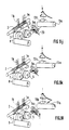
- the wire begins by being introduced between the first condenser (7) and the torsion blocking cylinder (8) and there is a displacement of the portion of the wire held between the blocker (8) and the shaft (13a) in the form of a variable-pitch helix with an exponential movement of the wire which allows rapid introduction of the portion of the tensioned wire inside all the other members of the spinning block, namely on the cover condenser (4) between the two belts (6a, 6b) of the spindle (6) and between the two elements (13a, 13b) of the deliverer (13 ) (phase illustrated in Figures 9h to 9d).
- the wire being thus positioned, all of the elements can be rewired (figure 91) so as to produce the piecing (figures 9m and 9n).
- the stretching system was closed and the wicks (1a, 1b) are, during the stabilization of the fibrous flow (duration: a few seconds), sent to the waste by the suction systems (24,25) .
- a surface abrasion device (27) is disposed upstream of this entry zone inside the spinning block on the one hand, in order to peel the end of the launching yarn and on the other hand, avoid any whiplash which might produce a fault in the piecing.
- the method according to the invention makes it possible to obtain a connection having the structure shown diagrammatically in FIG. 10.
- the piecing process begins at A.
- the thread ( 14) being introduced inside the spinning block: in the zone going from A to C, this launching thread (14) is firstly covered by the covering fibers (1a) then, from point C the distribution of the core fibers (1b) is started, the covering fibers (1a) cover the core fibers (1b) which are distributed; after cutting the launching wire (point E), the end possibly being refined in the zone EF, the core yarn (14) is obtained which must normally be produced on the machine.
- the length L3 of the CE zone is approximately 60% of the total length L of the patch, in order to obtain good resistance.
- the length L4 of the zone EF corresponding to the cut and thinned end of the launching wire (14) (shown in phantom in Figure 6) is, in turn, equal to about 10% of the total length of the patch .
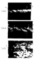
- FIGS. 11a to 11c are photographic reproductions showing the main phases of production of a patch according to the invention as described above.
- FIG. 11a corresponds to the zone of progressive introduction of the covering fibers (1a) onto the launching wire (14) (zone going from point A to point C of FIG. 10).
- FIG. 11b corresponds to the zone in which the progressive introduction of the core fibers (1b) takes place under the covering fibers (1a) to go to a double count of the normal thread count (DE zone of the figure 10).
- Figure 11c illustrates the end of the piecing (area EF) of Figure 10 in which the launch wire (14) is cut.
- Figures 12 and 13 show by way of indication two types of core fiber yarns for which the method according to the invention can be implemented. We can clearly see in these photographs the fibers (1b) forming the core and which are surrounded by the fibers (1a) forming the cover.
Landscapes
- Engineering & Computer Science (AREA)
- Mechanical Engineering (AREA)
- Textile Engineering (AREA)
- Spinning Or Twisting Of Yarns (AREA)
- Yarns And Mechanical Finishing Of Yarns Or Ropes (AREA)
Applications Claiming Priority (4)
| Application Number | Priority Date | Filing Date | Title |
|---|---|---|---|
| FR8910392 | 1989-07-27 | ||
| FR8910393 | 1989-07-27 | ||
| FR8910392A FR2650306B1 (fr) | 1989-07-27 | 1989-07-27 | Machine de filature permettant de realiser des files de fibres et procede de relance automatique sur une telle machine |
| FR8910393A FR2650308B1 (fr) | 1989-07-27 | 1989-07-27 | Procede pour la rattache de files de fibres comportant une ame et nouveau type de rattache ainsi realisee |
Publications (1)
| Publication Number | Publication Date |
|---|---|
| EP0410905A1 true EP0410905A1 (de) | 1991-01-30 |
Family
ID=26227499
Family Applications (1)
| Application Number | Title | Priority Date | Filing Date |
|---|---|---|---|
| EP90420346A Withdrawn EP0410905A1 (de) | 1989-07-27 | 1990-07-19 | Verfahren zum Wiederanspinnen von aus Fasern bestehenden Kerngarnen, neuartiges durch dieses Verfahren verwirklichtes Wiederanspinnen und Maschine hierzu |
Country Status (2)
| Country | Link |
|---|---|
| EP (1) | EP0410905A1 (de) |
| JP (1) | JPH03174037A (de) |
Cited By (1)
| Publication number | Priority date | Publication date | Assignee | Title |
|---|---|---|---|---|
| CN117431673A (zh) * | 2023-10-19 | 2024-01-23 | 兰溪新奥华纺织科技有限公司 | 一种芯层无捻包芯纱、成纱系统及方法 |
Citations (5)
| Publication number | Priority date | Publication date | Assignee | Title |
|---|---|---|---|---|
| FR1542261A (fr) * | 1966-11-04 | 1968-10-11 | Toyo Rayon Co Ltd | Procédé et appareil pour la fabrication de fils à partir de fibres textiles |
| DE2361969A1 (de) * | 1973-12-13 | 1975-06-26 | Zinser Textilmaschinen Gmbh | Fahrbare einrichtung zur selbsttaetigen behebung von fadenbruechen an textilmaschinen |
| GB2059453A (en) * | 1979-09-29 | 1981-04-23 | Schubert & Salzer Maschinen | Thread draw-off apparatus and method for initiating thread draw-off in an open-end spinning apparatus |
| EP0149107A2 (de) * | 1983-12-09 | 1985-07-24 | Schubert & Salzer Maschinenfabrik Aktiengesellschaft | Verfahren zum Bilden einer Fadenreservewicklung |
| WO1987003310A1 (fr) * | 1985-11-21 | 1987-06-04 | Schubert & Salzer Maschinenfabrik Aktiengesellscha | Procede et dispositif de renfilage d'un dispositif a filer pourvu d'un organe tordeur pneumatique |
-
1990
- 1990-07-19 EP EP90420346A patent/EP0410905A1/de not_active Withdrawn
- 1990-07-27 JP JP20107990A patent/JPH03174037A/ja active Pending
Patent Citations (5)
| Publication number | Priority date | Publication date | Assignee | Title |
|---|---|---|---|---|
| FR1542261A (fr) * | 1966-11-04 | 1968-10-11 | Toyo Rayon Co Ltd | Procédé et appareil pour la fabrication de fils à partir de fibres textiles |
| DE2361969A1 (de) * | 1973-12-13 | 1975-06-26 | Zinser Textilmaschinen Gmbh | Fahrbare einrichtung zur selbsttaetigen behebung von fadenbruechen an textilmaschinen |
| GB2059453A (en) * | 1979-09-29 | 1981-04-23 | Schubert & Salzer Maschinen | Thread draw-off apparatus and method for initiating thread draw-off in an open-end spinning apparatus |
| EP0149107A2 (de) * | 1983-12-09 | 1985-07-24 | Schubert & Salzer Maschinenfabrik Aktiengesellschaft | Verfahren zum Bilden einer Fadenreservewicklung |
| WO1987003310A1 (fr) * | 1985-11-21 | 1987-06-04 | Schubert & Salzer Maschinenfabrik Aktiengesellscha | Procede et dispositif de renfilage d'un dispositif a filer pourvu d'un organe tordeur pneumatique |
Non-Patent Citations (2)
| Title |
|---|
| PATENT ABSTRACTS OF JAPAN vol. 9, no. 283 (C-313)(2006) 09 novembre 1985, & JP-A-60 126330 (MURATA KIKAI K.K.) * |
| PATENT ABSTRACTS OF JAPAN vol. 9, no. 71 (C-272)(1794) 30 mars 1985, & JP-A-59 204925 (TOYODA JIDO SHOKKI SEISAKUSHO K.K.) * |
Cited By (1)
| Publication number | Priority date | Publication date | Assignee | Title |
|---|---|---|---|---|
| CN117431673A (zh) * | 2023-10-19 | 2024-01-23 | 兰溪新奥华纺织科技有限公司 | 一种芯层无捻包芯纱、成纱系统及方法 |
Also Published As
| Publication number | Publication date |
|---|---|
| JPH03174037A (ja) | 1991-07-29 |
Similar Documents
| Publication | Publication Date | Title |
|---|---|---|
| EP0085017B1 (de) | Vorrichtung zum Strecken, Verdichten und Zuführen einer Faserlunte während eines Spinnvorganges | |
| EP0085634B1 (de) | Verfahren und Einrichtung zur Herstellung eines Garns | |
| FR2481985A1 (fr) | Dispositif pour la coupe de fils continus, notamment de fils de verre | |
| EP0022421B1 (de) | Verfahren und Vorrichtung zum Herstellen eines Zwirnes mit über seine Länge abwechselnder S- und Z-Drehung | |
| EP0162787B1 (de) | Verfahren zum Herstellen eines umsponnenen Garnes | |
| EP0085635B1 (de) | Verfahren und Vorrichtung zum Herstellen von Coregarn | |
| FR2505370A1 (fr) | Procede et dispositif pour interrompre et commencer le filage dans un poste de filature a fibres liberees | |
| EP0005664A1 (de) | Verfahren zum Führen eines faserförmigen Materials von einer Aufwickelspindel zur anderen sowie Vorrichtung zur Durchführung des Verfahrens | |
| LU81825A1 (fr) | Procede et dispositif de lancement de fils en debut de renvidage | |
| EP0483601B1 (de) | Verfahren und Vorrichtung zum Herstellen eines Vlies aus Mehrfachfäden und Aufwickeln desselben auf einen Kettbaum | |
| EP0410905A1 (de) | Verfahren zum Wiederanspinnen von aus Fasern bestehenden Kerngarnen, neuartiges durch dieses Verfahren verwirklichtes Wiederanspinnen und Maschine hierzu | |
| EP1297204B1 (de) | Vorrichtung und verfahren zum schneiden von filamentlunten aus thermoplastischen material | |
| EP1369222A1 (de) | Verfahren zum selektiven Einbringen von Fäden in textilen multidimensionalen Vorformlingen und Vorrichtung zur Durchführung des Verfahrens | |
| FR2650306A1 (fr) | Machine de filature permettant de realiser des files de fibres et procede de relance automatique sur une telle machine | |
| FR2650308A1 (fr) | Procede pour la rattache de files de fibres comportant une ame et nouveau type de rattache ainsi realisee | |
| EP0208628B1 (de) | Einrichtung zur Regelung der Spannung eines Fadens bei verschiedenen die Fadeneigenschaften ändernden Produktionsstufen während seiner Herstellung | |
| FR2663916A1 (fr) | Dispositif de dechargement automatique de bobines textiles. | |
| CH625765A5 (de) | ||
| EP0410906A1 (de) | Maschine zur Herstellung und Verarbeitung von Fäden, mit einem Behandlungsorgan, das zwischen zwei Fadentransporteinrichtungen liegt und Verfahren zur automatischen Einführung von Fäden in das Innere dieser Elemente während des Wiederanspinnens | |
| BE1007920A5 (fr) | Systeme d'insertion de trame pour metier a jet de fluide. | |
| FR2538008A1 (fr) | Dispositif pour l'insertion d'un fil de trame dans la foule d'un metier a tisser | |
| FR2667581A1 (fr) | Dispositif pour la formation d'une reserve de fil sur une machine textile. | |
| FR2907798A1 (fr) | Procede de traitement de fils par tricotage-detricotage | |
| EP1380528B1 (de) | Verfahren zum automatischen Abheben von Spulen | |
| FR3131247A1 (fr) | Machine d'application de fibres equipee d'un systeme limiteur de tension |
Legal Events
| Date | Code | Title | Description |
|---|---|---|---|
| PUAI | Public reference made under article 153(3) epc to a published international application that has entered the european phase |
Free format text: ORIGINAL CODE: 0009012 |
|
| AK | Designated contracting states |
Kind code of ref document: A1 Designated state(s): AT CH DE IT LI |
|
| 17P | Request for examination filed |
Effective date: 19910227 |
|
| 17Q | First examination report despatched |
Effective date: 19920814 |
|
| STAA | Information on the status of an ep patent application or granted ep patent |
Free format text: STATUS: THE APPLICATION IS DEEMED TO BE WITHDRAWN |
|
| 18D | Application deemed to be withdrawn |
Effective date: 19921225 |