EP0411207B1 - Digitaler Empfänger mit Unter-Nyquistabtastrate - Google Patents
Digitaler Empfänger mit Unter-Nyquistabtastrate Download PDFInfo
- Publication number
- EP0411207B1 EP0411207B1 EP89121207A EP89121207A EP0411207B1 EP 0411207 B1 EP0411207 B1 EP 0411207B1 EP 89121207 A EP89121207 A EP 89121207A EP 89121207 A EP89121207 A EP 89121207A EP 0411207 B1 EP0411207 B1 EP 0411207B1
- Authority
- EP
- European Patent Office
- Prior art keywords
- subcarrier
- frequency
- signal
- sampling
- composite signal
- Prior art date
- Legal status (The legal status is an assumption and is not a legal conclusion. Google has not performed a legal analysis and makes no representation as to the accuracy of the status listed.)
- Expired - Lifetime
Links
- 238000005070 sampling Methods 0.000 title claims abstract description 36
- 239000002131 composite material Substances 0.000 claims description 18
- 238000000034 method Methods 0.000 claims description 6
- 238000001914 filtration Methods 0.000 claims 2
- 238000006243 chemical reaction Methods 0.000 claims 1
- 238000001228 spectrum Methods 0.000 description 9
- 238000010586 diagram Methods 0.000 description 4
- 230000010363 phase shift Effects 0.000 description 2
- 238000000926 separation method Methods 0.000 description 2
- 230000005540 biological transmission Effects 0.000 description 1
- 239000003990 capacitor Substances 0.000 description 1
- 238000001514 detection method Methods 0.000 description 1
- 235000014366 other mixer Nutrition 0.000 description 1
- 230000001360 synchronised effect Effects 0.000 description 1
Images
Classifications
-
- H—ELECTRICITY
- H03—ELECTRONIC CIRCUITRY
- H03D—DEMODULATION OR TRANSFERENCE OF MODULATION FROM ONE CARRIER TO ANOTHER
- H03D1/00—Demodulation of amplitude-modulated oscillations
- H03D1/22—Homodyne or synchrodyne circuits
- H03D1/2245—Homodyne or synchrodyne circuits using two quadrature channels
- H03D1/2254—Homodyne or synchrodyne circuits using two quadrature channels and a phase locked loop
-
- H—ELECTRICITY
- H04—ELECTRIC COMMUNICATION TECHNIQUE
- H04B—TRANSMISSION
- H04B1/00—Details of transmission systems, not covered by a single one of groups H04B3/00 - H04B13/00; Details of transmission systems not characterised by the medium used for transmission
- H04B1/06—Receivers
- H04B1/16—Circuits
- H04B1/1646—Circuits adapted for the reception of stereophonic signals
Definitions
- the present invention relates to digital data receivers, and more particularly relates to digital receivers that can digitally recover data by sampling at sub-Nyquist sampling rates and a method thereof.
- the present invention is described with reference to one particular application thereof, namely a system for recovering digital subcarrier data from a conventional FM broadcast signal. It should be recognized, however, that the invention is not so limited.
- Subcarriers on FM broadcast signals are increasingly being used to transmit digital data to subscribers of subcarrier data services.
- Data being transmitted by such services includes stock market reports and paging information.
- a sub-carrier-based paging system is disclosed in U.S. Patent 4,713,808 to Gaskill.
- a continuous signal must be sampled at a frequency above the Nyquist rate if the signal is to be properly characterised.
- the Nyquist rate is defined as twice the signal's highest frequency. If a sub-Nyquist rate is used, frequency aliasing results, causing various portions of the signal's spectrum to interfere with each other. If this interfere is uncontrolled, the signal can be lost or scrambled. That is, the sampled data may correspond to two or more different input signals. To avoid this possibility, most digital systems sample at rates well in excess of the Nyquist rate.
- the sampling problem was avoided by using phase shift keying.
- the data modulating the subcarrier was recovered at the wristwatch receiver by noting whether the subcarrier was in phase or out of phase with the pilot signal. This detection of the subcarrier phase was performed at a 19 KHz rate.
- phase shift keying method was advantageous in certain respects, it required a subcarrier bandwidth of 38 KHz to achieve a 19 Kbit transmission rate - an inefficient use of spectrum. Modulation of the subcarrier using amplitude modulation would have permitted more efficient use of the spectrum, but would have required sampling at a rate in excess of the Nyquist criteria - a feat difficult to achieve given the constraints associated with the wristwatch design.
- an object of the present invention to circumvent the Nyquist sampling criteria. More particularly, it is an object of the present invention to permit a digital receiver to sample an amplitude modulated subcarrier at sub-Nyquist rates in a manner that controls the frequency aliasing such that the aliasing produces a constructive interference between the upper and lower sidebands.
- Patent 4,688,253 discloses a receiver and method in accordance with the pre-characterising portions of claims 1 and 4 and shows a "left plus right" or L+R separation circuit that separates the L+R component from a composite stereo signal.
- the circuit shown in Patent 4,688,253 generates a sampling signal from the composite stereo.
- the sample signal has a frequency twice the subcarrier frequency. Sampling of the composite stereo occurs at the zero-crossing times of the subcarrier.
- Another prior patent, namely, German Patent DE 3,832,455 shows a receiver for receiving an amplitude modulated subcarrier carrying a data signal. Separation is done without sampling as in the present invention.
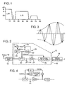
- a typical FM signal is composed of several components, as shown in Figure 1. Principal among these are the audio subbands.
- the left plus right channel audio is broadcast in a first subband extending from 0 to about 15 KHz.
- the left minus right channel audio is broadcast in a second subband extending from about 23 to 53 KHz. Between these two audio bands is a stereo pilot signal at 19 KHz.
- Subcarrier data is typically transmitted in the portion of the spectrum above 53 KHz.
- the subcarrier is at 66.5 KHz and is amplitude modulated with 19 KHz data. This 19 KHz modulation spreads the subcarrier signal from 57 to 76 KHz.
- the majority of the signal power is concentrated in the audio subbands.
- the subcarrier typically represents one percent or less of the transmitted power.
- an illustrative data receiver 10 includes an antenna 12, a front end 14 and a data decoder 16.
- the antenna 12 receives RF FM broadcast signals and provides them to the front end 14.
- the front end 14 converts these signals to baseband and provides the baseband signal spectrum to the data decoder 16.
- the data decoder recovers the data signals from the baseband spectrum and provides output signals corresponding thereto to a user interface 18.
- the data decoder 16 includes a frequency source 20 that generates a 133 KHz low duty cycle sampling clock signal which is phase locked to the 19 KHz stereo pilot signal.
- This phase locked frequency source 20 includes a voltage controlled oscillator 22, a frequency divider 24, a multiplier 26 and a low pass filter 28.
- the voltage controlled oscillator 22 operates nominally at 133 KHz.
- the frequency divider 24 divides the 133 KHz signal output from the oscillator by seven to yield a 19 KHz signal. This signal is mixed with the 19 KHz pilot signal from the composite FM signal by the mixer 26.
- the mixer output includes a low frequency difference term that represents a phase error between the voltage controlled oscillator output and the 19 KHz stereo pilot signal.
- This low frequency signal is filtered from all the other mixer products by the low pass filter 28 and is applied in a feedback loop back to the oscillator 22 to correct its frequency.
- the loop thus operates to lock the phase of the 133 KHz oscillator 22 to the phase of the stereo pilot signal.
- the 66.5 KHz subcarrier is itself generated from the 19 KHz stereo pilot by a phase locked frequency multiplier circuit. Consequently, the 133 KHz sampling clock produced by the frequency source 20 is phase locked to the 66.5 KHz subcarrier being decoded.
- the radio station also includes provision for adjusting the phase offset between the 19 KHz pilot signal and the 66.5 KHz subcarrier so that the receiver of the present invention samples at the peaks of the subcarrier waveform.
- the 133 KHz sampling clock in the Fig. 2 embodiment is used to periodically trigger an analog sample and hold circuit 30, which operates in conjunction with an analog storage device, such as a capacitor 32.
- the sampled analog signal produced thereby is converted into digital form, again at the 133 KHz rate, by an analog-to-digital converter 34.
- These digital samples are applied to a 32 element finite impulse response digital filter 36 that passes the 66.5 KHz modulated subcarrier and attenuates the entertainment programming portions of the baseband FM spectrum.
- the resulting signal output from the filter 36 contains just the subcarrier portion of the baseband spectrum, sampled at a 133 KHz rate. This data is decoded and the resulting output signals applied to the user interface 18.
- each zero crossing of the carrier signal forces a zero crossing in the composite baseband signal. Since the times of the zero crossings of the baseband signal are known, its maxima and minima can be accurately approximated as the points midway between the zero crossings. Since the sampling clock is phase locked to the subcarrier frequency, it can sample, reliably, at approximately these mid points. This sampling at known maxima and minima is graphically illustrated in Fig. 3. Since the signal maxima and minima can be accurately determined, the modulating signal can readily be recovered, despite non-compliance with the Nyquist criteria.
- Figure 4 shows a portion of another form of the present invention in which the phase locking circuitry is implemented in digital form, using a numerically controlled oscillator, a digital low pass filter, etc.
Landscapes
- Engineering & Computer Science (AREA)
- Power Engineering (AREA)
- Computer Networks & Wireless Communication (AREA)
- Signal Processing (AREA)
- Digital Transmission Methods That Use Modulated Carrier Waves (AREA)
- Transmission Systems Not Characterized By The Medium Used For Transmission (AREA)
- Circuits Of Receivers In General (AREA)
- Synchronisation In Digital Transmission Systems (AREA)
Claims (4)
- Empfänger zum Empfangen eines amplitudenmodulierten Zwischenträgers, wobei besagter Zwischenträger als Teil eines RF-Signalgemischs übertragen wird, das ein Pilotsignal enthält, und der Empfänger folgendes umfaßt: eine vorderste Stufe (14) zum Konvertieren des RF-Signalgemischs in ein Grundfrequenzbandsignalgemisch; eine Frequenzquelle (20) zum Herstellen eines Abtasttaktsignals; Mittel (26, 28) zum Phasenverriegeln besagter Frequenzquelle (20) mit dem Pilotsignal in dem Grundfrequensbandsignalgemisch; und ein Abtastmittel (30) zum Abtasten besagten Signalgemischs mit einer Rate, die von dem Abtasttaktsignal bestimmt ist; gekennzeichnet dadurch, daß: besagtes Abtasttaktsignal eine Frequenz aufweist, die kleiner als das Zweifache der maximalen Frequenz des modulierten Zwischenträgers ist; ein Analog-Digital-Umwandlungsmittel (34) zum Umwandeln der von dem Abtastmittel produzierten Proben in digitale Form und ein digitales Filtermittel (36) zum digitalen Filtern besagter digitalisierter Proben zum Dämpfen der Nichtzwischenträgerkomponenten derselben vorhanden ist; wobei besagtes Signalgemisch an den Zeitpunkten abgetastet wird, an welchen der Zwischenträger seine Maximalwerte annimmt.
- Empfänger nach Anspruch 1, dadurch gekennzeichnet, daß die Frequenzquelle (20) ein Mittel zum Herstellen eines Abtasttaktsignals mit einer Frequenz enthält, die ein ganzzahliges Vielfaches der Pilotsignalfrequenz ist.
- Empfänger nach Anspruch 2, dadurch gekennzeichnet, daß das Pilotsignal eine Frequenz von 19 kHz; das Zwischenträgersignal eine Trägerfrequenz von 66,5 kHz und das Abtasttaktsignal eine Frequenz von 133 kHz hat.
- Verfahren zum Empfangen von Daten, die auf einen Zwischenträger eines Signalgemischs moduliert worden sind, wobei das Verfahren die folgenden Schritte umfaßt: Ableiten (20) einer Referenzfrequenz aus besagtem Signalgemisch mit einer bekannten Beziehung zu der Zwischenträgerfrequenz; und periodisches Abtasten (30) des Signalgemischs unter bestimmten Phasenbedingungen der Referenzfrequenz; wobei besagtes Abtasten bei einer Frequenz stattfindet, die doppelt so groß wie die Zwischenträgerfrequenz ist; gekennzeichnet durch: Digitalisierung (34) des abgetasteten Signalgemischs um Digitaldaten zu erhalten; und Filtern (36) besagter Digitaldaten, um die Nichtzwischenträgerkomponenten des digitalisierten Signalgemischs zu dämpfen; wobei besagtes Signalgemisch an Zeitpunkten abgetastet wird, bei denen der Zwischenträger seine Maximalwerte annimmt.
Applications Claiming Priority (2)
| Application Number | Priority Date | Filing Date | Title |
|---|---|---|---|
| US388186 | 1988-08-01 | ||
| US07/388,186 US4893341A (en) | 1989-08-01 | 1989-08-01 | Digital receiver operating at sub-nyquist sampling rate |
Publications (3)
| Publication Number | Publication Date |
|---|---|
| EP0411207A2 EP0411207A2 (de) | 1991-02-06 |
| EP0411207A3 EP0411207A3 (en) | 1992-02-05 |
| EP0411207B1 true EP0411207B1 (de) | 1994-10-12 |
Family
ID=23533045
Family Applications (1)
| Application Number | Title | Priority Date | Filing Date |
|---|---|---|---|
| EP89121207A Expired - Lifetime EP0411207B1 (de) | 1989-08-01 | 1989-11-16 | Digitaler Empfänger mit Unter-Nyquistabtastrate |
Country Status (7)
| Country | Link |
|---|---|
| US (1) | US4893341A (de) |
| EP (1) | EP0411207B1 (de) |
| JP (1) | JPH02192251A (de) |
| AT (1) | ATE112905T1 (de) |
| CA (1) | CA2004248A1 (de) |
| DE (1) | DE68918857T2 (de) |
| ES (1) | ES2064419T3 (de) |
Families Citing this family (53)
| Publication number | Priority date | Publication date | Assignee | Title |
|---|---|---|---|---|
| GB2242800B (en) * | 1990-04-03 | 1993-11-24 | Sony Corp | Digital phase detector arrangements |
| US5416806A (en) * | 1992-06-15 | 1995-05-16 | International Business Machines Corporation | Timing loop method and apparatus for PRML data detection |
| DE4303387A1 (de) * | 1993-02-05 | 1994-08-11 | Blaupunkt Werke Gmbh | Schaltungsanordnung zur Decodierung eines Multiplexsignals in einem Stereo-Rundfunkempfänger |
| JPH07162383A (ja) * | 1993-12-07 | 1995-06-23 | Hitachi Denshi Ltd | Fmステレオ放送装置 |
| US5610825A (en) * | 1994-11-08 | 1997-03-11 | Johnson; William J. | Method and apparatus for the display of digitized analog signal loss |
| US5768374A (en) * | 1996-08-06 | 1998-06-16 | Transcrypt International | Apparatus and method for continuous scrambling while transmitting or receiving synchronization data |
| US6295362B1 (en) * | 1998-01-20 | 2001-09-25 | General Instrument Corporation | Direct digital synthesis of FM signals |
| US6694128B1 (en) | 1998-08-18 | 2004-02-17 | Parkervision, Inc. | Frequency synthesizer using universal frequency translation technology |
| US6061551A (en) | 1998-10-21 | 2000-05-09 | Parkervision, Inc. | Method and system for down-converting electromagnetic signals |
| US7515896B1 (en) | 1998-10-21 | 2009-04-07 | Parkervision, Inc. | Method and system for down-converting an electromagnetic signal, and transforms for same, and aperture relationships |
| US6091940A (en) | 1998-10-21 | 2000-07-18 | Parkervision, Inc. | Method and system for frequency up-conversion |
| US6813485B2 (en) | 1998-10-21 | 2004-11-02 | Parkervision, Inc. | Method and system for down-converting and up-converting an electromagnetic signal, and transforms for same |
| US6049706A (en) | 1998-10-21 | 2000-04-11 | Parkervision, Inc. | Integrated frequency translation and selectivity |
| US7039372B1 (en) | 1998-10-21 | 2006-05-02 | Parkervision, Inc. | Method and system for frequency up-conversion with modulation embodiments |
| US7321735B1 (en) | 1998-10-21 | 2008-01-22 | Parkervision, Inc. | Optical down-converter using universal frequency translation technology |
| US7295826B1 (en) | 1998-10-21 | 2007-11-13 | Parkervision, Inc. | Integrated frequency translation and selectivity with gain control functionality, and applications thereof |
| US6370371B1 (en) | 1998-10-21 | 2002-04-09 | Parkervision, Inc. | Applications of universal frequency translation |
| US6061555A (en) | 1998-10-21 | 2000-05-09 | Parkervision, Inc. | Method and system for ensuring reception of a communications signal |
| US6560301B1 (en) * | 1998-10-21 | 2003-05-06 | Parkervision, Inc. | Integrated frequency translation and selectivity with a variety of filter embodiments |
| US7236754B2 (en) | 1999-08-23 | 2007-06-26 | Parkervision, Inc. | Method and system for frequency up-conversion |
| US6542722B1 (en) | 1998-10-21 | 2003-04-01 | Parkervision, Inc. | Method and system for frequency up-conversion with variety of transmitter configurations |
| US6704549B1 (en) | 1999-03-03 | 2004-03-09 | Parkvision, Inc. | Multi-mode, multi-band communication system |
| US7006805B1 (en) | 1999-01-22 | 2006-02-28 | Parker Vision, Inc. | Aliasing communication system with multi-mode and multi-band functionality and embodiments thereof, such as the family radio service |
| US6704558B1 (en) | 1999-01-22 | 2004-03-09 | Parkervision, Inc. | Image-reject down-converter and embodiments thereof, such as the family radio service |
| US6873836B1 (en) | 1999-03-03 | 2005-03-29 | Parkervision, Inc. | Universal platform module and methods and apparatuses relating thereto enabled by universal frequency translation technology |
| US6853690B1 (en) * | 1999-04-16 | 2005-02-08 | Parkervision, Inc. | Method, system and apparatus for balanced frequency up-conversion of a baseband signal and 4-phase receiver and transceiver embodiments |
| US6879817B1 (en) | 1999-04-16 | 2005-04-12 | Parkervision, Inc. | DC offset, re-radiation, and I/Q solutions using universal frequency translation technology |
| US7110435B1 (en) | 1999-03-15 | 2006-09-19 | Parkervision, Inc. | Spread spectrum applications of universal frequency translation |
| US7693230B2 (en) | 1999-04-16 | 2010-04-06 | Parkervision, Inc. | Apparatus and method of differential IQ frequency up-conversion |
| US7065162B1 (en) * | 1999-04-16 | 2006-06-20 | Parkervision, Inc. | Method and system for down-converting an electromagnetic signal, and transforms for same |
| US7110444B1 (en) | 1999-08-04 | 2006-09-19 | Parkervision, Inc. | Wireless local area network (WLAN) using universal frequency translation technology including multi-phase embodiments and circuit implementations |
| US7072390B1 (en) | 1999-08-04 | 2006-07-04 | Parkervision, Inc. | Wireless local area network (WLAN) using universal frequency translation technology including multi-phase embodiments |
| US8295406B1 (en) | 1999-08-04 | 2012-10-23 | Parkervision, Inc. | Universal platform module for a plurality of communication protocols |
| US7054296B1 (en) | 1999-08-04 | 2006-05-30 | Parkervision, Inc. | Wireless local area network (WLAN) technology and applications including techniques of universal frequency translation |
| US7082171B1 (en) | 1999-11-24 | 2006-07-25 | Parkervision, Inc. | Phase shifting applications of universal frequency translation |
| US6963734B2 (en) | 1999-12-22 | 2005-11-08 | Parkervision, Inc. | Differential frequency down-conversion using techniques of universal frequency translation technology |
| US7292835B2 (en) * | 2000-01-28 | 2007-11-06 | Parkervision, Inc. | Wireless and wired cable modem applications of universal frequency translation technology |
| US7010286B2 (en) * | 2000-04-14 | 2006-03-07 | Parkervision, Inc. | Apparatus, system, and method for down-converting and up-converting electromagnetic signals |
| US7554508B2 (en) | 2000-06-09 | 2009-06-30 | Parker Vision, Inc. | Phased array antenna applications on universal frequency translation |
| US7010559B2 (en) | 2000-11-14 | 2006-03-07 | Parkervision, Inc. | Method and apparatus for a parallel correlator and applications thereof |
| US7454453B2 (en) * | 2000-11-14 | 2008-11-18 | Parkervision, Inc. | Methods, systems, and computer program products for parallel correlation and applications thereof |
| US7085335B2 (en) | 2001-11-09 | 2006-08-01 | Parkervision, Inc. | Method and apparatus for reducing DC offsets in a communication system |
| US7072427B2 (en) * | 2001-11-09 | 2006-07-04 | Parkervision, Inc. | Method and apparatus for reducing DC offsets in a communication system |
| US6975848B2 (en) | 2002-06-04 | 2005-12-13 | Parkervision, Inc. | Method and apparatus for DC offset removal in a radio frequency communication channel |
| US7321640B2 (en) | 2002-06-07 | 2008-01-22 | Parkervision, Inc. | Active polyphase inverter filter for quadrature signal generation |
| US7460584B2 (en) * | 2002-07-18 | 2008-12-02 | Parkervision, Inc. | Networking methods and systems |
| US7379883B2 (en) * | 2002-07-18 | 2008-05-27 | Parkervision, Inc. | Networking methods and systems |
| US6942660B2 (en) * | 2002-11-19 | 2005-09-13 | Conmed Corporation | Electrosurgical generator and method with multiple semi-autonomously executable functions |
| TWI280690B (en) * | 2003-03-18 | 2007-05-01 | Tdk Corp | Electronic device for wireless communications and reflector device for wireless communication cards |
| US7945004B2 (en) | 2007-12-14 | 2011-05-17 | Motorola Mobility, Inc. | Method and apparatus for detecting a frequency band and mode of operation |
| GB0725111D0 (en) | 2007-12-21 | 2008-01-30 | Wolfson Microelectronics Plc | Lower rate emulation |
| US8055222B2 (en) | 2008-12-16 | 2011-11-08 | Motorola Mobility, Inc. | Multiple protocol signal detector |
| EP3782405A1 (de) * | 2018-04-20 | 2021-02-24 | Telefonaktiebolaget Lm Ericsson (Publ) | Verfahren und vorrichtung zum energieeffizienten senden und empfangen eines signals unter verwendung von aliasing |
Family Cites Families (3)
| Publication number | Priority date | Publication date | Assignee | Title |
|---|---|---|---|---|
| US4757538A (en) * | 1986-07-07 | 1988-07-12 | Tektronix, Inc. | Separation of L+R from L-R in BTSC system |
| US4688253A (en) * | 1986-07-28 | 1987-08-18 | Tektronix, Inc. | L+R separation system |
| JP2571247B2 (ja) * | 1988-01-07 | 1997-01-16 | パイオニア株式会社 | ラジオデータ受信機における受信周波数選択方法 |
-
1989
- 1989-08-01 US US07/388,186 patent/US4893341A/en not_active Expired - Lifetime
- 1989-11-16 EP EP89121207A patent/EP0411207B1/de not_active Expired - Lifetime
- 1989-11-16 AT AT89121207T patent/ATE112905T1/de not_active IP Right Cessation
- 1989-11-16 ES ES89121207T patent/ES2064419T3/es not_active Expired - Lifetime
- 1989-11-16 DE DE68918857T patent/DE68918857T2/de not_active Expired - Lifetime
- 1989-11-20 JP JP1299895A patent/JPH02192251A/ja active Pending
- 1989-11-30 CA CA002004248A patent/CA2004248A1/en not_active Abandoned
Also Published As
| Publication number | Publication date |
|---|---|
| CA2004248A1 (en) | 1991-02-01 |
| DE68918857D1 (de) | 1994-11-17 |
| US4893341A (en) | 1990-01-09 |
| EP0411207A3 (en) | 1992-02-05 |
| ES2064419T3 (es) | 1995-02-01 |
| EP0411207A2 (de) | 1991-02-06 |
| DE68918857T2 (de) | 1995-03-02 |
| ATE112905T1 (de) | 1994-10-15 |
| JPH02192251A (ja) | 1990-07-30 |
Similar Documents
| Publication | Publication Date | Title |
|---|---|---|
| EP0411207B1 (de) | Digitaler Empfänger mit Unter-Nyquistabtastrate | |
| DE69320868T2 (de) | Empfänger mit einem kombinierten AM-FM-Demodulator | |
| US5390348A (en) | System for tracking and correcting drift and dispersion in satellite transmission signals | |
| US4827515A (en) | Digital demodulator | |
| US5438589A (en) | Spread spectrum communication system | |
| AU544712B2 (en) | Remote control receiver | |
| JP2809097B2 (ja) | 無線局装置 | |
| WO1992015163A1 (en) | Method and apparatus for real-time demodulation of a gmsk signal by a non-coherent receiver | |
| EP0193396B1 (de) | Optisches Signalübertragungssystem mit Pulsfrequenzmodulations-Modem | |
| US5857003A (en) | Digital radio having improved modulation and detection processes | |
| KR19990072574A (ko) | 디지털mpx신호복조기용반송파발생장치 | |
| US5444744A (en) | Phase locked loop for synchronizing with carrier wave | |
| US4238783A (en) | Telemetry system for transmitting analog data over a telephone line | |
| US6005886A (en) | Synchronization-free spread-spectrum demodulator | |
| GB2093318A (en) | Fm broadcasting system with transmitter identification | |
| US4006416A (en) | Digital communication system | |
| US4744094A (en) | BPSK demodulator with D type flip/flop | |
| US4622683A (en) | Fast acquisition ringing filter MSK demodulator | |
| KR100290857B1 (ko) | 디지털 티브이(Digital TV)의 클럭 복원장치 | |
| US4388726A (en) | System for the ultra-high frequency transmission of numerical data | |
| KR100254127B1 (ko) | 디지탈 발진기 | |
| US6985541B1 (en) | FM demodulator for a low IF receiver | |
| EP0868019A3 (de) | FM-Multiplex-Rundunkempfänger | |
| US11063798B2 (en) | High spectral efficiency zero bandwidth modulation process without side bands | |
| JP3495568B2 (ja) | クロック再生回路 |
Legal Events
| Date | Code | Title | Description |
|---|---|---|---|
| PUAI | Public reference made under article 153(3) epc to a published international application that has entered the european phase |
Free format text: ORIGINAL CODE: 0009012 |
|
| AK | Designated contracting states |
Kind code of ref document: A2 Designated state(s): AT BE CH DE ES FR GB GR IT LI LU NL SE |
|
| PUAL | Search report despatched |
Free format text: ORIGINAL CODE: 0009013 |
|
| AK | Designated contracting states |
Kind code of ref document: A3 Designated state(s): AT BE CH DE ES FR GB GR IT LI LU NL SE |
|
| 17P | Request for examination filed |
Effective date: 19920617 |
|
| RAP1 | Party data changed (applicant data changed or rights of an application transferred) |
Owner name: SEIKO EPSON CORPORATION Owner name: SEIKO CORPORATION |
|
| 17Q | First examination report despatched |
Effective date: 19930625 |
|
| ITF | It: translation for a ep patent filed | ||
| GRAA | (expected) grant |
Free format text: ORIGINAL CODE: 0009210 |
|
| AK | Designated contracting states |
Kind code of ref document: B1 Designated state(s): AT BE CH DE ES FR GB GR IT LI LU NL SE |
|
| PG25 | Lapsed in a contracting state [announced via postgrant information from national office to epo] |
Ref country code: AT Effective date: 19941012 Ref country code: CH Effective date: 19941012 Ref country code: NL Effective date: 19941012 Ref country code: LI Effective date: 19941012 Ref country code: BE Effective date: 19941012 Ref country code: GR Free format text: LAPSE BECAUSE OF FAILURE TO SUBMIT A TRANSLATION OF THE DESCRIPTION OR TO PAY THE FEE WITHIN THE PRESCRIBED TIME-LIMIT Effective date: 19941012 |
|
| REF | Corresponds to: |
Ref document number: 112905 Country of ref document: AT Date of ref document: 19941015 Kind code of ref document: T |
|
| REF | Corresponds to: |
Ref document number: 68918857 Country of ref document: DE Date of ref document: 19941117 |
|
| PG25 | Lapsed in a contracting state [announced via postgrant information from national office to epo] |
Ref country code: LU Free format text: LAPSE BECAUSE OF NON-PAYMENT OF DUE FEES Effective date: 19941130 |
|
| ET | Fr: translation filed | ||
| PG25 | Lapsed in a contracting state [announced via postgrant information from national office to epo] |
Ref country code: SE Effective date: 19950112 |
|
| REG | Reference to a national code |
Ref country code: CH Ref legal event code: PL |
|
| REG | Reference to a national code |
Ref country code: ES Ref legal event code: FG2A Ref document number: 2064419 Country of ref document: ES Kind code of ref document: T3 |
|
| NLV1 | Nl: lapsed or annulled due to failure to fulfill the requirements of art. 29p and 29m of the patents act | ||
| PLBE | No opposition filed within time limit |
Free format text: ORIGINAL CODE: 0009261 |
|
| STAA | Information on the status of an ep patent application or granted ep patent |
Free format text: STATUS: NO OPPOSITION FILED WITHIN TIME LIMIT |
|
| 26N | No opposition filed | ||
| REG | Reference to a national code |
Ref country code: GB Ref legal event code: IF02 |
|
| REG | Reference to a national code |
Ref country code: FR Ref legal event code: TP |
|
| REG | Reference to a national code |
Ref country code: GB Ref legal event code: 732E |
|
| PGFP | Annual fee paid to national office [announced via postgrant information from national office to epo] |
Ref country code: DE Payment date: 20081114 Year of fee payment: 20 |
|
| PGFP | Annual fee paid to national office [announced via postgrant information from national office to epo] |
Ref country code: ES Payment date: 20081216 Year of fee payment: 20 |
|
| PGFP | Annual fee paid to national office [announced via postgrant information from national office to epo] |
Ref country code: IT Payment date: 20081126 Year of fee payment: 20 |
|
| PGFP | Annual fee paid to national office [announced via postgrant information from national office to epo] |
Ref country code: FR Payment date: 20081106 Year of fee payment: 20 |
|
| PGFP | Annual fee paid to national office [announced via postgrant information from national office to epo] |
Ref country code: GB Payment date: 20081008 Year of fee payment: 20 |
|
| REG | Reference to a national code |
Ref country code: GB Ref legal event code: PE20 Expiry date: 20091115 |
|
| REG | Reference to a national code |
Ref country code: ES Ref legal event code: FD2A Effective date: 20091117 |
|
| PG25 | Lapsed in a contracting state [announced via postgrant information from national office to epo] |
Ref country code: ES Free format text: LAPSE BECAUSE OF EXPIRATION OF PROTECTION Effective date: 20091117 Ref country code: GB Free format text: LAPSE BECAUSE OF EXPIRATION OF PROTECTION Effective date: 20091115 |