EP0411243A1 - Allumeur pour sous-munition du type "bomblet" - Google Patents
Allumeur pour sous-munition du type "bomblet" Download PDFInfo
- Publication number
- EP0411243A1 EP0411243A1 EP19900105124 EP90105124A EP0411243A1 EP 0411243 A1 EP0411243 A1 EP 0411243A1 EP 19900105124 EP19900105124 EP 19900105124 EP 90105124 A EP90105124 A EP 90105124A EP 0411243 A1 EP0411243 A1 EP 0411243A1
- Authority
- EP
- European Patent Office
- Prior art keywords
- slide
- detonator
- firing
- igniter
- projectile
- Prior art date
- Legal status (The legal status is an assumption and is not a legal conclusion. Google has not performed a legal analysis and makes no representation as to the accuracy of the status listed.)
- Granted
Links
Images

Classifications
-
- F—MECHANICAL ENGINEERING; LIGHTING; HEATING; WEAPONS; BLASTING
- F42—AMMUNITION; BLASTING
- F42C—AMMUNITION FUZES; ARMING OR SAFETY MEANS THEREFOR
- F42C9/00—Time fuzes; Combined time and percussion or pressure-actuated fuzes; Fuzes for timed self-destruction of ammunition
- F42C9/14—Double fuzes; Multiple fuzes
- F42C9/142—Double fuzes; Multiple fuzes combined time and percussion fuzes in which the timing is caused by combustion
-
- F—MECHANICAL ENGINEERING; LIGHTING; HEATING; WEAPONS; BLASTING
- F42—AMMUNITION; BLASTING
- F42C—AMMUNITION FUZES; ARMING OR SAFETY MEANS THEREFOR
- F42C1/00—Impact fuzes, i.e. fuzes actuated only by ammunition impact
- F42C1/02—Impact fuzes, i.e. fuzes actuated only by ammunition impact with firing-pin structurally combined with fuze
-
- F—MECHANICAL ENGINEERING; LIGHTING; HEATING; WEAPONS; BLASTING
- F42—AMMUNITION; BLASTING
- F42C—AMMUNITION FUZES; ARMING OR SAFETY MEANS THEREFOR
- F42C15/00—Arming-means in fuzes; Safety means for preventing premature detonation of fuzes or charges
- F42C15/18—Arming-means in fuzes; Safety means for preventing premature detonation of fuzes or charges wherein a carrier for an element of the pyrotechnic or explosive train is moved
- F42C15/184—Arming-means in fuzes; Safety means for preventing premature detonation of fuzes or charges wherein a carrier for an element of the pyrotechnic or explosive train is moved using a slidable carrier
Definitions
- the invention relates to a detonator for an explosive projectile, in particular a submunition projectile (bomblet), according to the preamble of patent claim 1.
- Such a bomb detonator with an axially unscrewable main firing needle and transversely to the longitudinal direction of the projectile from a securing position into a focusable slide with detonator charge is such.
- a firing element of a pyrotechnic delay line which can be ignited by a second firing needle is provided for a self-dismantling of the projectile after the detonator has not been triggered in the event of a target impact by the main firing needle.
- This can e.g. B. happen when such a projectile ejected from a carrier floor (bomblet) lands on soft ground, mud, snow, tree branches or a camouflage net.
- a disadvantage of the known bomblet construction is the fact that when the ignition device is in focus, the slide protrudes laterally far and unprotected from the igniter housing. As a result, z. B. in rainy weather misfires easily occur in the detonator charge or the exposed ignition element of the delay charge for self-decomposition.
- Another disadvantage is the arrangement of the second ignition needle for igniting the ignition element on the outer unprotected end of the slide itself, which protrudes far out of the side of the fuse housing.
- the second ignition needle is provided with a heavy striking piece and is rotatably fastened to the slide by means of a bolt.
- the striking piece When focusing by moving the slide laterally out of the detonator housing, the striking piece should pass through Centrifugal force from the self-rotation of the bomblet take effect and the massive firing needle should move about 90 ° on a pitch circle with a small radius and penetrate into the ignition element.
- the shape of the ignition needle tip is solidly conical with a flattening on one side, possibly to facilitate penetration into the ignition element on a small circular arc.
- This detonator construction also has the major disadvantage that large unbalances during rotation and thereby destabilizing forces act on the bomblet due to the slide projecting far out of the detonator housing with an outside heavyweight firing pin impact piece.
- the well-known second firing pin with a solid conical shape more or less closes this opening during the ignition process, depending on how deep it penetrates.
- the ignition needle should penetrate as deeply as possible, but then the tap opening is completely closed and the ignition can lead to extinction due to the poor possibility of the combustion gases being emitted.
- the second firing needle is expediently an integrated component (connected in one piece) of a circular spring plate made of a thin sheet metal, which has a strip-like spring tongue in the center, which engages in a recess arranged below the slide in the focus position of the slide and thus prevents the slide from rebounding and prevents it securely fixed in focus position.
- the spring tongue is not loaded when the slide is secured, but is only depressed when the slide is displaced transversely and is therefore not subject to signs of fatigue during long storage.
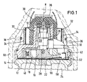
- the reference number 10 denotes an igniter housing, which is fixed in place on a bomblet housing 12 by means of a retaining ring 14.
- a slide 16 Arranged within the detonator housing 10 is a slide 16 with detonator charge 18 which can be displaced transversely to the central axis A of the bomblet floor.
- the illustration shows the slide 16 in a secured position, the detonator charge 18 being shifted laterally out of the straight line between a main firing needle 20 and an amplifier charge 22 arranged in the upper bomblet housing 12 in order to ignite the main explosive charge 24.
- the centrally arranged main firing needle 20 is connected via a screw connection to a sleeve 26, which serves as an additional impact mass and can be displaced axially in the igniter housing 10.
- the firing needle 20 is screwed into the sleeve 26, so that it is supported upwards or backwards against a shoulder of the igniter housing 10.
- the tip 28 of the main ignition needle 20 projects into a recess (blind hole) arranged on the upper side of the slide 16 and thus fixes the slide 16 in the securing position.
- a folded stabilizing band 30 is attached to the end of the main firing needle 20 protruding from the igniter housing 10.
- On the outside of the igniter housing 10 and surrounding the upper diameter-reduced area of the igniter housing 10 are two radially outwardly pivotable, semicircularly curved swirl brake vanes 32, e.g. B. made of thin sheet steel.
- a wrapping band 34 is placed around the swirl brake vanes 32 that are folded in.
- the winding tape 34 and the stabilizing tape 30 are held in their wound position by a hood-like, two-part plastic clip 36, which in turn is held in position by a spring steel retaining ring 38.
- the daughter floors When they are transported to a target area by means of a large-caliber carrier floor that can be closed over long distances (e.g. 30 km), the daughter floors are stacked one inside the other in a space-saving manner as columns.
- a neighboring bomblet 60 which completely covers the detonator housing 10, is indicated in FIG.
- the detonator housing 10 extends far into the conical free space of the shaped charge insert of the adjacent bomblet 60.
- the stabilizing band 30 is pulled out of its folded rest position and unfolded.
- the plastic clip 36 with the retaining ring 38 jumps off the igniter housing 10 and releases the winding tape 34.
- the detachable winding tape 34 unwinds and releases the swirl brake blades 32, which swivel out due to the centrifugal forces caused by the rotation and reduce the swirl of the now stabilized falling bomblet projectile.
- the center of gravity of the slide 16 is set so that it is arranged in the securing position (on the left in FIG. 1) next to the central axis A, as a result of which the centrifugal forces push the slide 16 (to the left) against the force of a compression spring 40 in the event of a high swirl.
- the second ignition needle 42 arranged laterally within the detonator housing 10 for initiating an ignition element 44 of a pyrotechnic delay line 46 with a reinforcement set 48 and an explosive explosive charge 50 is designed in a sheet-metal strip-like manner with a pointed cone-shaped cut so that it can penetrate deeply into the ignition set 44 for safe initiation without flowing out to obstruct the resulting combustion gases.
- the second firing needle 42 represents an integrated tongue-like bent sheet metal strip part of a flat spring plate disk 52, which is arranged in the direct vicinity of the slide 16 and covers the entire cross section of the igniter housing 10.
- the tongue-like bent-up spring which is perpendicular to the spring plate disk 52 is supported Part of the second firing needle 42 on the back on the inner wall of the igniter housing 10.
- the second firing needle 42 or the spring plate 52 expediently has a material thickness or plate thickness of 0.1 to 0.8 mm, preferably approximately 0.4 mm.
- the second firing needle 42 is arranged asymmetrically with respect to the central axis B of the slide 16 in a direct line with the ignition element 44 of the pyrotechnic delay line 46, the end region of which is arranged directly next to the detonator charge 18 with a reinforcement set 48 and an explosive explosive charge 50.
- the spring metal plate 52 expediently has an integrated spring tongue 54, which is in a blocking operative connection with a corresponding recess 56 on the underside of the slide 16 in the arming position of the slide. If the slider 16 is moved into the focus position, it is locked by the spring tongue 54, which latches into the recess 56 on the underside of the slider 16.
- the known spring tongue permanently pressed onto the slide in the securing position. At low rotational speeds, the centrifugal force or a spring force was often not sufficient to overcome the frictional force between the known spring tongue and slide and to move the slide into focus and to apply the piercing energy that was then necessary.
- the spring washer 52 is fixed to the igniter housing 10 by a thin-walled covering hood 58 which overlaps the igniter housing 10.
- the covering hood 58 expediently has the same sheet thickness as the spring sheet metal disk 52.
- the spring tongue 54 engages in the recess 56 and fixes the slide 16 in this position.
- the detonator charge 18 is now arranged in a line exactly below the tip 28 of the main ignition needle 20, which normally initiates the detonator charge 18 in the event of a hard target impact, which brings the booster charge 22 and thus the main explosive charge 24 to ignition and detonation.
- the spring plate disk 52 and / or the thin cover hood 58 can have a central bore.
- the delay set 46 burns after z. B. 20 seconds and ignites the reinforcement set 46, which develops a high combustion temperature, and the explosive powder containing explosive charge 50, which nevertheless activate the detonator charge 18 arranged next to it in a short way.
- the inventive construction of the bomb detonator ensures a trouble-free ignition of the igniter element for subsequent self-destruction or detonation of the bomb in any case while reducing the height and weight of the detonator.
Landscapes
- Engineering & Computer Science (AREA)
- General Engineering & Computer Science (AREA)
- Air Bags (AREA)
- Portable Nailing Machines And Staplers (AREA)
Applications Claiming Priority (2)
| Application Number | Priority Date | Filing Date | Title |
|---|---|---|---|
| DE3925235A DE3925235A1 (de) | 1989-07-29 | 1989-07-29 | Bombletzuender |
| DE3925235 | 1989-07-29 |
Publications (2)
| Publication Number | Publication Date |
|---|---|
| EP0411243A1 true EP0411243A1 (fr) | 1991-02-06 |
| EP0411243B1 EP0411243B1 (fr) | 1993-11-18 |
Family
ID=6386173
Family Applications (1)
| Application Number | Title | Priority Date | Filing Date |
|---|---|---|---|
| EP90105124A Expired - Lifetime EP0411243B1 (fr) | 1989-07-29 | 1990-03-19 | Allumeur pour sous-munition du type "bomblet" |
Country Status (3)
| Country | Link |
|---|---|
| US (1) | US5048419A (fr) |
| EP (1) | EP0411243B1 (fr) |
| DE (2) | DE3925235A1 (fr) |
Cited By (3)
| Publication number | Priority date | Publication date | Assignee | Title |
|---|---|---|---|---|
| WO1996035095A1 (fr) * | 1995-05-05 | 1996-11-07 | Dixi S.A. | Dispositif de securite pour fusee percutante |
| FR2801099A1 (fr) * | 1999-11-17 | 2001-05-18 | Giat Ind Sa | Systeme d'amorcage de la charge explosive d'une sous- munition |
| FR2816400A1 (fr) * | 2000-11-07 | 2002-05-10 | Giat Ind Sa | Dispositif d'amorcage de la charge explosive d'une sous-munition |
Families Citing this family (18)
| Publication number | Priority date | Publication date | Assignee | Title |
|---|---|---|---|---|
| FR2699660B1 (fr) * | 1992-12-18 | 1995-02-24 | Giat Ind Sa | Système d'amorçage et d'auto-destruction d'une munition, en particulier d'une sous-munition destinée à être éjectée d'un obus cargo avec un mouvement de rotation propre autour d'un axe. |
| DE4335022C2 (de) * | 1993-10-14 | 1998-06-10 | Rheinmetall Ind Ag | Zünd- und Sicherungseinrichtung mit Selbstzerlegungseinrichtung für ein mit einer Hohlladungseinlage versehenes Granatengeschoß |
| DE9419261U1 (de) * | 1994-12-01 | 1996-04-04 | Gebrüder Junghans GmbH, 78713 Schramberg | Aufschlagzünder für Munition |
| SE504857C2 (sv) * | 1995-04-27 | 1997-05-12 | Bofors Ab | Sätt vid substridsdel samt substridsdel |
| FR2737293B1 (fr) * | 1995-07-27 | 1997-10-17 | Giat Ind Sa | Systeme d'amorcage de la charge explosive d'une sous-munition embarquee dans un engin porteur |
| US5932834A (en) * | 1997-04-24 | 1999-08-03 | The United States Of America As Represented By The Secretary Of The Army | Auto-destruct fuze |
| DE19726951C2 (de) * | 1997-06-25 | 1999-12-16 | Rheinmetall W & M Gmbh | Zünder für ein Drallgeschoß mit im Verriegelungsbolzen für den Detonatorträger angeordneter Selbstzerlegereinheit |
| DE19842541C2 (de) * | 1998-09-17 | 2003-10-16 | Rheinmetall W & M Gmbh | Stabilisierungsbandbefestigung bei einer Abwurfmunition |
| DE19917121C2 (de) * | 1999-04-15 | 2002-03-21 | Rheinmetall W & M Gmbh | Submunitionsgeschoss mit einem durch die Anströmkräfte der Luft aus der Sicherungsposition freigebbaren Schieber |
| DE19916775C2 (de) | 1999-04-15 | 2002-12-05 | Rheinmetall W & M Gmbh | Submunitionsgeschoß |
| FR2799830B1 (fr) * | 1999-10-18 | 2002-08-30 | Giat Ind Sa | Dispositif et procede de fixation d'un systeme d'amorcage sur un corps d'une grenade |
| US6302025B1 (en) * | 2000-04-17 | 2001-10-16 | The United States Of America As Represented By The Secretary Of The Army | Self destruct fuze with improved slide assembly |
| US6705231B1 (en) * | 2000-12-04 | 2004-03-16 | The United States Of America As Represented By The Secretary Of The Army | Safing and arming device for artillery submunitions |
| US6874425B1 (en) * | 2001-05-18 | 2005-04-05 | Day & Zimmermann, Inc. | Projectile carrying sub-munitions |
| US6968785B2 (en) * | 2003-09-22 | 2005-11-29 | The United States Of America As Represented By The Secretary Of The Army | Locking and stabilizing device for grenades |
| BE1016094A3 (fr) * | 2004-05-14 | 2006-03-07 | Zeebrugge Forges Sa | Dispositif d'autodestruction pour fusee de sous-munition. |
| US20100175261A1 (en) * | 2008-07-22 | 2010-07-15 | L.I.F.E. Support Technologies, Llc | Safety razor |
| CN113935074B (zh) * | 2021-09-17 | 2023-01-31 | 北京理工大学 | 一种用于存储器瞬态自毁系统的安全控制芯片 |
Citations (7)
| Publication number | Priority date | Publication date | Assignee | Title |
|---|---|---|---|---|
| DE265386C (fr) * | ||||
| US1702133A (en) * | 1926-04-26 | 1929-02-12 | Remondy Leon Emile | Supersensitive fuse for projectiles of all calibers |
| DE3333312A1 (de) * | 1983-09-15 | 1985-04-04 | Rheinmetall GmbH, 4000 Düsseldorf | Zuender fuer ein tochtergeschoss |
| DE3524080A1 (de) * | 1985-07-05 | 1987-01-08 | Rheinmetall Gmbh | Zuender fuer einen gefechtskopf |
| FR2607918A1 (fr) * | 1986-12-04 | 1988-06-10 | Dynamit Nobel Ag | Fusee percutante pour projectiles a effet gyroscopique |
| EP0318996A2 (fr) * | 1987-12-03 | 1989-06-07 | DIEHL GMBH & CO. | Allumeur pyrotechnique pour projectiles, roquettes bombes et mines |
| EP0318995A2 (fr) * | 1987-12-03 | 1989-06-07 | DIEHL GMBH & CO. | Allumeur pyrotechnique pour projectiles |
Family Cites Families (9)
| Publication number | Priority date | Publication date | Assignee | Title |
|---|---|---|---|---|
| US3724384A (en) * | 1965-09-27 | 1973-04-03 | Us Navy | Centrifugally armed fuze |
| US3913483A (en) * | 1972-08-11 | 1975-10-21 | Us Army | Grenade with fuze |
| US3998164A (en) * | 1975-12-15 | 1976-12-21 | The United States Of America As Represented By The Secretary Of The Army | Self-destruct delay fuze |
| US4455940A (en) * | 1982-06-28 | 1984-06-26 | The United States Of America As Represented By The Secretary Of The Army | Random time delay fuze |
| IT1183906B (it) * | 1985-06-28 | 1987-10-22 | Borletti Spa | Spoletta con autodistruzione per submunizione atta ad essere espulsa da un vettore |
| IT1183905B (it) * | 1985-06-28 | 1987-10-22 | Borletti Spa | Spoletta per submunizione atta ad essere espulsa da un vettore |
| DE3624713C2 (de) * | 1986-07-22 | 1995-09-07 | Diehl Gmbh & Co | Aufschlagzünder mit Selbstzerlegeeinrichtung für einen Bomblet |
| IL82066A (en) * | 1987-03-31 | 1992-03-29 | Israel State | Fuse for sub-munition warhead |
| US4770096A (en) * | 1987-08-17 | 1988-09-13 | Honeywell Inc. | Safing and arming mechanism |
-
1989
- 1989-07-29 DE DE3925235A patent/DE3925235A1/de not_active Withdrawn
-
1990
- 1990-03-19 DE DE90105124T patent/DE59003515D1/de not_active Expired - Fee Related
- 1990-03-19 EP EP90105124A patent/EP0411243B1/fr not_active Expired - Lifetime
- 1990-07-30 US US07/559,346 patent/US5048419A/en not_active Expired - Fee Related
Patent Citations (7)
| Publication number | Priority date | Publication date | Assignee | Title |
|---|---|---|---|---|
| DE265386C (fr) * | ||||
| US1702133A (en) * | 1926-04-26 | 1929-02-12 | Remondy Leon Emile | Supersensitive fuse for projectiles of all calibers |
| DE3333312A1 (de) * | 1983-09-15 | 1985-04-04 | Rheinmetall GmbH, 4000 Düsseldorf | Zuender fuer ein tochtergeschoss |
| DE3524080A1 (de) * | 1985-07-05 | 1987-01-08 | Rheinmetall Gmbh | Zuender fuer einen gefechtskopf |
| FR2607918A1 (fr) * | 1986-12-04 | 1988-06-10 | Dynamit Nobel Ag | Fusee percutante pour projectiles a effet gyroscopique |
| EP0318996A2 (fr) * | 1987-12-03 | 1989-06-07 | DIEHL GMBH & CO. | Allumeur pyrotechnique pour projectiles, roquettes bombes et mines |
| EP0318995A2 (fr) * | 1987-12-03 | 1989-06-07 | DIEHL GMBH & CO. | Allumeur pyrotechnique pour projectiles |
Cited By (5)
| Publication number | Priority date | Publication date | Assignee | Title |
|---|---|---|---|---|
| WO1996035095A1 (fr) * | 1995-05-05 | 1996-11-07 | Dixi S.A. | Dispositif de securite pour fusee percutante |
| FR2801099A1 (fr) * | 1999-11-17 | 2001-05-18 | Giat Ind Sa | Systeme d'amorcage de la charge explosive d'une sous- munition |
| FR2816400A1 (fr) * | 2000-11-07 | 2002-05-10 | Giat Ind Sa | Dispositif d'amorcage de la charge explosive d'une sous-munition |
| WO2002039049A1 (fr) * | 2000-11-07 | 2002-05-16 | Giat Industries | Dispositif d'amorcage de la charge explosive d'une sous-munition |
| US6848367B2 (en) | 2000-11-07 | 2005-02-01 | Giat Industries | Priming device for the explosive charge of a sub-munition |
Also Published As
| Publication number | Publication date |
|---|---|
| EP0411243B1 (fr) | 1993-11-18 |
| DE3925235A1 (de) | 1991-01-31 |
| US5048419A (en) | 1991-09-17 |
| DE59003515D1 (de) | 1993-12-23 |
Similar Documents
| Publication | Publication Date | Title |
|---|---|---|
| EP0411243B1 (fr) | Allumeur pour sous-munition du type "bomblet" | |
| EP0364670B1 (fr) | Grenade | |
| EP0764826B1 (fr) | Projectile porteur supportant un projectile unique secondaire du type pénétrateur | |
| EP0158700B1 (fr) | Fusée pour projectile secondaire | |
| DE3624713A1 (de) | Zuender fuer ein fallschirm- oder bandstabilisiertes, im flug rotierendes bomblett | |
| EP0411258B1 (fr) | Dispositif d'allumage pour une sous munition | |
| DE3149346C2 (fr) | ||
| EP0602632B1 (fr) | Fusée à sécurité de bouche et projectile comportant une telle fusée | |
| DE2725256A1 (de) | Gewehrgranate | |
| DE69609255T2 (de) | Vorrichtung zum Zünden einer Treibladung für eine aus einem Trägergeschoss geworfene Submunition | |
| EP0042957A2 (fr) | Fusée pour projectiles à rotation | |
| CH657450A5 (de) | Beharrungszuender fuer drallgeschosse mit selbstzerlegereinrichtung. | |
| EP0358961B1 (fr) | Fusée d'impact à sécurité de bouche | |
| DE10111714C1 (de) | Zünder für ein aus einem Rohr mit Drall abzuschießendes Geschoss | |
| EP0227919B1 (fr) | Fusée d'impact pour projectile | |
| EP0342399A1 (fr) | Dispositif pour désamorcer des projectiles non explosés | |
| DE4030917C2 (de) | Drehzahlbereich abhängig entsicherbarer Zünder für ein Sprenggeschoß | |
| DE4034630C2 (de) | Durch Wärmeeinwirkung entsicherbarer Zünder | |
| DE4226129C2 (de) | Aufschlagzünder mit Vorrohrsicherheit für ein Übungsgeschoß | |
| DE3936065C2 (de) | Mine, insbesondere Landmine | |
| DE2149117A1 (de) | Geschosszuender | |
| DE7709752U1 (de) | Zuendverzoegerungsvorrichtung | |
| DE2010881C3 (de) | Handgranatenzünder | |
| DE1578445A1 (de) | Einer Drehbewegung ausgesetzter Zuender,insbesondere fuer Kleinkalibergeschosse | |
| EP0232296A1 (fr) | Fusee a double effet pour projectiles |
Legal Events
| Date | Code | Title | Description |
|---|---|---|---|
| PUAI | Public reference made under article 153(3) epc to a published international application that has entered the european phase |
Free format text: ORIGINAL CODE: 0009012 |
|
| 17P | Request for examination filed |
Effective date: 19900921 |
|
| AK | Designated contracting states |
Kind code of ref document: A1 Designated state(s): CH DE FR GB IT LI SE |
|
| 17Q | First examination report despatched |
Effective date: 19920804 |
|
| RAP3 | Party data changed (applicant data changed or rights of an application transferred) |
Owner name: RHEINMETALL GMBH |
|
| ITF | It: translation for a ep patent filed | ||
| GRAA | (expected) grant |
Free format text: ORIGINAL CODE: 0009210 |
|
| AK | Designated contracting states |
Kind code of ref document: B1 Designated state(s): CH DE FR GB IT LI SE |
|
| GBT | Gb: translation of ep patent filed (gb section 77(6)(a)/1977) |
Effective date: 19931118 |
|
| REF | Corresponds to: |
Ref document number: 59003515 Country of ref document: DE Date of ref document: 19931223 |
|
| ET | Fr: translation filed | ||
| PLBE | No opposition filed within time limit |
Free format text: ORIGINAL CODE: 0009261 |
|
| STAA | Information on the status of an ep patent application or granted ep patent |
Free format text: STATUS: NO OPPOSITION FILED WITHIN TIME LIMIT |
|
| 26N | No opposition filed | ||
| EAL | Se: european patent in force in sweden |
Ref document number: 90105124.3 |
|
| REG | Reference to a national code |
Ref country code: GB Ref legal event code: IF02 |
|
| PGFP | Annual fee paid to national office [announced via postgrant information from national office to epo] |
Ref country code: GB Payment date: 20020222 Year of fee payment: 13 |
|
| PGFP | Annual fee paid to national office [announced via postgrant information from national office to epo] |
Ref country code: CH Payment date: 20020225 Year of fee payment: 13 |
|
| PGFP | Annual fee paid to national office [announced via postgrant information from national office to epo] |
Ref country code: SE Payment date: 20020305 Year of fee payment: 13 |
|
| PGFP | Annual fee paid to national office [announced via postgrant information from national office to epo] |
Ref country code: DE Payment date: 20020309 Year of fee payment: 13 |
|
| PGFP | Annual fee paid to national office [announced via postgrant information from national office to epo] |
Ref country code: FR Payment date: 20020315 Year of fee payment: 13 |
|
| PG25 | Lapsed in a contracting state [announced via postgrant information from national office to epo] |
Ref country code: GB Free format text: LAPSE BECAUSE OF NON-PAYMENT OF DUE FEES Effective date: 20030319 |
|
| PG25 | Lapsed in a contracting state [announced via postgrant information from national office to epo] |
Ref country code: SE Free format text: LAPSE BECAUSE OF NON-PAYMENT OF DUE FEES Effective date: 20030320 |
|
| PG25 | Lapsed in a contracting state [announced via postgrant information from national office to epo] |
Ref country code: LI Free format text: LAPSE BECAUSE OF NON-PAYMENT OF DUE FEES Effective date: 20030331 Ref country code: CH Free format text: LAPSE BECAUSE OF NON-PAYMENT OF DUE FEES Effective date: 20030331 |
|
| PG25 | Lapsed in a contracting state [announced via postgrant information from national office to epo] |
Ref country code: DE Free format text: LAPSE BECAUSE OF NON-PAYMENT OF DUE FEES Effective date: 20031001 |
|
| EUG | Se: european patent has lapsed | ||
| GBPC | Gb: european patent ceased through non-payment of renewal fee |
Effective date: 20030319 |
|
| REG | Reference to a national code |
Ref country code: CH Ref legal event code: PL |
|
| PG25 | Lapsed in a contracting state [announced via postgrant information from national office to epo] |
Ref country code: FR Free format text: LAPSE BECAUSE OF NON-PAYMENT OF DUE FEES Effective date: 20031127 |
|
| REG | Reference to a national code |
Ref country code: FR Ref legal event code: ST |
|
| PG25 | Lapsed in a contracting state [announced via postgrant information from national office to epo] |
Ref country code: IT Free format text: LAPSE BECAUSE OF NON-PAYMENT OF DUE FEES;WARNING: LAPSES OF ITALIAN PATENTS WITH EFFECTIVE DATE BEFORE 2007 MAY HAVE OCCURRED AT ANY TIME BEFORE 2007. THE CORRECT EFFECTIVE DATE MAY BE DIFFERENT FROM THE ONE RECORDED. Effective date: 20050319 |