EP0411286A1 - Pâte thermique à base d'une matrice métallique liquide - Google Patents
Pâte thermique à base d'une matrice métallique liquide Download PDFInfo
- Publication number
- EP0411286A1 EP0411286A1 EP90111402A EP90111402A EP0411286A1 EP 0411286 A1 EP0411286 A1 EP 0411286A1 EP 90111402 A EP90111402 A EP 90111402A EP 90111402 A EP90111402 A EP 90111402A EP 0411286 A1 EP0411286 A1 EP 0411286A1
- Authority
- EP
- European Patent Office
- Prior art keywords
- liquid metal
- metal matrix
- paste
- thermal
- gallium
- Prior art date
- Legal status (The legal status is an assumption and is not a legal conclusion. Google has not performed a legal analysis and makes no representation as to the accuracy of the status listed.)
- Granted
Links
Images


Classifications
-
- H—ELECTRICITY
- H10—SEMICONDUCTOR DEVICES; ELECTRIC SOLID-STATE DEVICES NOT OTHERWISE PROVIDED FOR
- H10W—GENERIC PACKAGES, INTERCONNECTIONS, CONNECTORS OR OTHER CONSTRUCTIONAL DETAILS OF DEVICES COVERED BY CLASS H10
- H10W40/00—Arrangements for thermal protection or thermal control
- H10W40/20—Arrangements for cooling
- H10W40/25—Arrangements for cooling characterised by their materials
- H10W40/257—Arrangements for cooling characterised by their materials having a heterogeneous or anisotropic structure, e.g. powder or fibres in a matrix, wire mesh or porous structures
-
- B—PERFORMING OPERATIONS; TRANSPORTING
- B22—CASTING; POWDER METALLURGY
- B22F—WORKING METALLIC POWDER; MANUFACTURE OF ARTICLES FROM METALLIC POWDER; MAKING METALLIC POWDER; APPARATUS OR DEVICES SPECIALLY ADAPTED FOR METALLIC POWDER
- B22F1/00—Metallic powder; Treatment of metallic powder, e.g. to facilitate working or to improve properties
- B22F1/17—Metallic particles coated with metal
-
- B—PERFORMING OPERATIONS; TRANSPORTING
- B22—CASTING; POWDER METALLURGY
- B22F—WORKING METALLIC POWDER; MANUFACTURE OF ARTICLES FROM METALLIC POWDER; MAKING METALLIC POWDER; APPARATUS OR DEVICES SPECIALLY ADAPTED FOR METALLIC POWDER
- B22F1/00—Metallic powder; Treatment of metallic powder, e.g. to facilitate working or to improve properties
- B22F1/18—Non-metallic particles coated with metal
-
- C—CHEMISTRY; METALLURGY
- C22—METALLURGY; FERROUS OR NON-FERROUS ALLOYS; TREATMENT OF ALLOYS OR NON-FERROUS METALS
- C22C—ALLOYS
- C22C1/00—Making non-ferrous alloys
- C22C1/02—Making non-ferrous alloys by melting
Definitions
- the present invention relates to thermal paste and particularly relates to a liquid metal matrix thermal paste.
- the thermal paste is used to form a thermal joint between an electronic component, such as a chip, and a cooling system.
- Modern very high performance electronic systems often require a high density of chips having many high power gates. These electronic systems require cooling a high power density through a limited temperature drop from a device junction to a cooling system. In order to achieve the cooling requirement, the thermal joint from the chip to the cooling system must possess a high thermal conductivity.
- the joint in addition to providing high thermal conductivity, must compensate for certain manufacturing tolerances inherent in any electronic assembly.
- C4 controlled collapse circuit connector technique
- the thermal joint must permit a certain amount of differential motion of the individual chips forming an electrical system assembly.
- manufacturing tolerances cause variations of the gap between the chip and the cooling system.
- a commonly used paste contains a mixture of zinc oxide in mineral oil. Such pastes have an upper limit of thermal conductivity. Also, the liquid and particles tend to phase separate after many power on-off cycles.
- the conventional pastes rely upon the perculation of oxide particles in a low conductivity oil matrix for thermal conductivity. The use of a low conductivity oil matrix is the primary limiting factor in achieving high thermal conductivity.
- Another object of the invention is the provision of a liquid metal matrix thermal paste containing fine thermally conducting particles dispersed in a low temperature liquid metal matrix which is stable for an indefinite period of time and which exhibits high thermal conductivity and adjustable viscosity.
- a further object of the invention is the provision of a liquid metal matrix thermal paste having high thermal conductivity for use as a thermal joint between an electrical component, such as a chip, and a cooling system, or between successive parts of a cooling system.
- a still further object of the invention is the provision of a process for preparing a liquid metal matrix thermal paste.
- the present invention provides a liquid metal matrix thermal paste containing fine thermally conductive particles dispersed in a low melting temperature liquid metal matrix.
- the particles are metal or conductive non-metals selected to be nonreactive with the liquid metal matrix at low temperature in order to provide a semi-liquid fully compliant structure for an indefinite period of time.
- the particles are preferably tungsten, molybdenum, silicon or other metals or high thermal conductivity materials which have a very low interaction rate with gallium, tin and indium at low temperature, i.e. at temperatures below approximately 100°C.
- the particles can also be non-metals having high thermal conductivity, such as diamonds.
- the particles can be coated to enhance wettability.
- the preferred liquid metal matrix are gallium and indium eutectic alloys, gallium and tin eutectic alloys, and gallium, indium and tin ternary eutectic alloys.
- the thermal paste of the present invention provides the highest available thermal conductivity thermal joint between a chip or component and the cooling system obtained to date, thereby showing this high thermal conductivity in both, the liquid matrix and the disposed particles.
- the liquid metal matrix thermal paste is formulated as described below as a gallium-metal paste which permanently and indefinitely retains its semi-liquid state under normal operating conditions and environment to serve as a compliant thermal interface.
- the resultant paste acts as a high thermal conductive medium which is formed into a desired shape to enhance thermal transfer.
- the enhanced thermal transfer via the paste is sustained during many on-off power cycles when the components of the cooling system expand and contract.
- the differential expansion of the various components results in significant thermal stresses, which are particularly damaging at the component interfaces.
- a paste which solidifies over time, and therefore, does not provide a compliant interface, will eventually crack after repeated expansion and contraction and cease to function as a good thermal transfer medium.
- liquid metal matrix thermal paste disclosed in claim 1 the thermal cooling system disclosed in claim 9 and the method disclosed in claim 12.
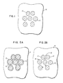
- Fig. 1 there is shown schematically in cross-section a liquid metal matrix thermal paste.
- the thermal paste contains thermally conductive particles 12, dispersed in a liquid metal matrix 14.
- the liquid metal matrix thermal paste of the present invention comprises fine thermally conductive particles dispersed in a low melting temperature liquid metal matrix.
- Preferred liquid metals are gallium and indium eutectic (75.4 wt % + 24.6 wt%, mp 15.7°C), gallium and tin eutectic (86.3 wt% + 13.7 wt%, mp 20.5°C), gallium, indium and tin ternary eutectic (21.5 wt% + 16.0 wt% + 62.5 wt%, mp 10.7°C), and several quarternary systems having melting points as low as 7°C.
- the ratios in parentheses are the preferred mixture composition and melting point of each alloy.
- the particles are metals or thermally conductive non-metals.
- the particles are selected to be non-reactive with the liquid metal, such as gallium, at low temperatures of less than approximately 100°C in order to provide a semi-liquid fully compliant paste for an indefinite period of time.
- Preferred particles are tungsten, molybdenum, silicon or other particles having a low interaction rate with gallium at low temperatures, i.e. at temperatures below approximately 100°C.
- Most of the particle materials, particularly silicon, molybdenum or tungsten will have an oxide layer on the surface which will impede wetting by a liquid metal. Therefore, referring to Fig. 2A, such particles are coated with a thin layer of a noble metal 16, such as gold, palladium or silver, with the preferred metal being gold.
- the thin noble metal layer e.g. gold, dissolves in gallium without affecting the composition significantly thereby ensuring wetting between the exposed metal particle and the gallium.
- gold-gallium intermetallics 18 are formed and remain attached to the particles.
- spherical particles are preferred.
- Commonly available tungsten and molybdenum powders are not spherical, but rather are of an irregular shape.
- spherical metallic particles such as copper
- a barrier layer of tungsten or molybdenum which, in turn, is coated by a thin layer of a noble metal, such as gold.
- the tungsten or molybdenum particles may be made spherical using any of several known techniques, a preferred technique being plasma remelting and solidification of the particles.
- the liquid metal matrix paste is prepared using conventional paste making techniques.
- the preferred method is a combination of planetary mixing and a three roll mill dispersion.
- the mixing hardware should be coated with one of the numerous available coatings, such as tungsten, oxides, nitrides or carbides of any one of several elements, in order to prevent contamination of the paste by dissolved elements.
- Liquid gallium and its alloys have a thermal conductivity of approximately 28 W/m ⁇ K.
- Solid tungsten has a thermal conductivity of 170 W/m ⁇ K.
- a dispersion of tungsten in a liquid gallium matrix will have a thermal conductivity in the range between 28 and 170 W/m ⁇ K. The exact value of the thermal conducting will depend upon fraction and dispersion of the solid phase in the resultant paste.
- the mathematical expression of the thermal resistivity of a joint contains bulk thermal resistivity and surface thermal resistivity terms.
- the bulk thermal resistivity term is proportional to the joint thickness.
- the surface thermal resistivity term is dependent upon particle size and surface finish.
- the surface thermal resistivity term is generally independent of the joint thickness provided it is a large value compared to the particle size term.
- the particle size provides a limit on the minimum joint thickness.
- the particle size also sets a scale for the magnitude of the surface effects. For a given joint thickness, reduction of a particle size as well as bimodal distribution will diminish the surface effects contribution to thermal resistance.
- a thermal resistivity of this magnitude is considered excellent for most applications.
- polymeric or other barriers including encapsulating compounds as fillers of the empty space between components, may be used.
- Certain families of chips are required to be electrically isolated from the metal joint. Applying chemical vapor deposited amorphous carbon to the chip at a moderate temperature, even after the chips have been bonded to the common substrate of the multi-chip module, provides a reliable pinhole free electrical insulator having a very low thermal resistivity.
- the application of thin dielectrics, such as SiO2 or SiN, to each wafer before dicing also provides electrical isolation. In certain wafer processing steps SiO2 is formed on the chip which then can be stripped off or left on the wafer as required.
- a blotter which can even be a fine mesh of a metal wire, is used.
- thermal resistivity is improved when the thermal joint is thin.
- low viscosity thermal paste is required.
- Pending U.S. Patent Application Serial No. 07/161,880 describes forming of a 25 ⁇ m (1 mil) thick paste joint by simultaneously shearing and compressing conventional thermal paste between a chip and a cooling unit. The same technique applies when using liquid metal matrix thermal paste provided the paste is not excessively stiff.
- a paste comprising 35 wt% Ga-In-Sn ternary eutectic and 65 wt% tungsten in the form of 10 ⁇ m particle size has been thinned to approximately 75-125 ⁇ m (3 to 5 mils) between two quartz slides while maintaining bubble-free interfaces.
- a paste containing 50 wt% tungsten in the form of 2.2 ⁇ m particle size in 50 wt% Ga-In-Sn ternary eutectic was successfully thinned to 50-75 ⁇ m (2 to 3 mils). Further reduction in joint thickness is possible by optimization of the thinning technique.
- Liquid metal matrix thermal paste according to the present invention in certain applications, can be melted for only a short period of time.
- the brief melt period differs from solder reflow because the liquid metal remains as a liquid metal matrix thermal paste throughout the entire temperature cycle.
- a gallium-tin system is a preferred suitable system for the described semi-liquid metal matrix.
- Fig. 3 is a phase diagram of a gallium and tin system. The ordinate axis is the temperature of the mixture and the abscissa represents increasing percentage of tin. At temperatures above the curve 20 for particular ratios of tin and gallium, the mixture is a liquid. Below the horizontal line 22 the mixture is a solid. For combinations of temperature and tin-gallium ratios between the curves 20 and 22 the mixture will be a semi-liquid of variable viscosity depending upon whether the operating point at a particular ratio of tin and gallium is closer to the "liquid line" 20 or "solid line” 22.
- vertical line 24 represents a 65 wt% Sn 35 wt% Ga alloy.
- the alloy is 63 wt% solid and 37 wt% liquid.
- the thermal paste will be applied to operate for use at an operating temperature of 70°C, the alloy will be 50 wt% solid and 50 wt% liquid.
- the paste exhibits very low viscosity during heating at a temperature in the range between 100°C and 130°C.
- the alloy After the cooling hardware is assembled and operating at a temperature in the range between 50° and 80°C, the alloy will exhibit increased viscosity. The described system will effectively prevent phase separation of the paste in service.
- Figs. 4A and 4B The system operation is shown schematically in Figs. 4A and 4B.
- thermally conductive particles 30 are dispersed in a liquid metal matrix 32 comprising 65 wt% tin and 35 wt% gallium at a temperature of 130°C.
- the metal matrix is substantially all liquid.
- tin 34 separates from the metal matrix with some quantity of tin adhering to the particles 30.
- the metal matrix is partially solid and partially liquid thus increasing the viscosity of the paste.
- An alternative method of reducing the possibility of phase separation of the thermal paste and thus ensuring low viscosity of the paste during assembly of the cooling structure and increased viscosity during normal operating conditions is to increase the thickness of the wettable layer on the particles.
- the particles 40 such as tungsten
- a liquid metal matrix 42 such as gallium, indium and tin ternary eutectic alloy
- a relatively thick layer of a wettable metal 44 such as gold.
- the liquid gallium, indium and tin react with the gold layer to produce intermetallic particles 46 as shown in Fig. 5B, the paste viscosity increases and the possibility of phase separation is reduced.
- Rework generally entails the removal of thermal paste.
- the bulk of the paste is removable by using metal wool containing tin or copper filaments.
- Thorough paste removal usually requires the use of ultrasonic agitation through a thin film of liquid without disturbing other components.
- Thorough paste removal is also achievable by using a brush or a felt tip and a cleaning liquid.
- Such a liquid should be non-corrosive and not be a strong organic solvent.
- Preferred liquids are isopropanol or ethanol. Also preferred is hypercritical carbon dioxide.
- Alternative paste removal methods include brushing with metal wool while using tin powder as a sweeping agent and placing tin foil in contact with the residual paste for removing gallium.
- a non-reactive coating is applied to the chip.
- the preferred coatings include an ultra thin layer of Teflon or siloxane applied by sputtering and hydrogenated amorphous carbon applied by chemical vapor deposition.
- a thin tungsten coating applied either by chemical vapor deposition or by sputtering achieves similar results. Both tungsten and hydrogenated carbon coatings have withstood 100 hour exposure at 200°C in contact with gallium, indium and tin eutectic liquid without any interaction being observed by various analytical techniques. As an additional benefit, these coatings assist in the prevention of thermomigration into and through a semiconductor material to prevent unwanted doping of the chip.
- Si - Au alloyed powder of 80 wt% Si - 20 wt% Au composite if stabilized at a temperature in the temperature range between 200°C and 300°C, comprises a silicon phase with a gold phase dispersed therein.
- Such a powder is capable of being produced conventionally by gas atomization.
- the gallium will preferentially react with gold, while not reacting with the silicon. The result is enhanced wetting and dispersion possibly to a greater extent than surface coating alone. If the gold is located inside the silicon particle, channels will be formed through the particles when the gold reacts with the gallium.
- the liquid metal matrix thermal paste has application with various types of cold plates.
- the paste may also be used with a piston cooling hat, between the chip and the piston as well as between the piston and cylinder.
- the paste is usable as a thermal joint which is adjacent to the chip, near but not adjacent to the chip and external to the cooling hat.
- the thermal paste is used with discrete components, particularly power components such as rectifiers, transistors and resistors.
- Example I is a thermal paste of 50 wt% gallium and 50 wt% Mo.
- the thermal paste was used as a thermal joint between a single chip and a cooling system.
- the power density was 103 W/cm2 through a total temperature differential of 64°C including both the joint and other thermal resistivities.
- Example II is a thermal paste of 33 wt% Ga-In-Sn ternary eutectic and 67 wt% tungsten comprising irregularly shaped particles having diameters in the range between 5 and 20 ⁇ m.
- the mixture was mixed in a "Wig-L-Bug" intense vibrator, and subsequently dispersed in a three-roll mill.
- the bulk thermal conductivity of the paste was measured at 45 W/mK, which is higher than the bulk thermal conductivity of most organic based commercially available thermal paste by a factor of approximately 50 times.
- the thermal paste was applied to the same sample chip thermal test module as in Example I.
- the thermal paste was spread on the module, then simultaneously squeezed and sheared to a thin, approximately 37 ⁇ m thick, layer.
- Interpolating the result to a temperature drop of 60°C yields a power density of 501 W/cm2.
- the thermal resistivity is the temperature drop across the paste multiplied by the chip area and divided by the power, expressed in units of °C per W/cm2 or in units of K per W/cm2.
- the total ThRy includes the paste itself and all the other components of the thermal path including the cooling hat.
- the cooling bath water flow was 8 cm3/sec over a cold plate having an area of 1.1 cm2.
Landscapes
- Chemical & Material Sciences (AREA)
- Engineering & Computer Science (AREA)
- Materials Engineering (AREA)
- Mechanical Engineering (AREA)
- Metallurgy (AREA)
- Organic Chemistry (AREA)
- Cooling Or The Like Of Semiconductors Or Solid State Devices (AREA)
- Cooling Or The Like Of Electrical Apparatus (AREA)
- Conductive Materials (AREA)
Applications Claiming Priority (2)
| Application Number | Priority Date | Filing Date | Title |
|---|---|---|---|
| US38913189A | 1989-08-03 | 1989-08-03 | |
| US389131 | 1989-08-03 |
Publications (2)
| Publication Number | Publication Date |
|---|---|
| EP0411286A1 true EP0411286A1 (fr) | 1991-02-06 |
| EP0411286B1 EP0411286B1 (fr) | 1994-12-28 |
Family
ID=23536954
Family Applications (1)
| Application Number | Title | Priority Date | Filing Date |
|---|---|---|---|
| EP90111402A Expired - Lifetime EP0411286B1 (fr) | 1989-08-03 | 1990-06-16 | Pâte thermique à base d'une matrice métallique liquide |
Country Status (4)
| Country | Link |
|---|---|
| EP (1) | EP0411286B1 (fr) |
| JP (1) | JPH0729213B2 (fr) |
| CA (1) | CA2018930C (fr) |
| DE (1) | DE69015491T2 (fr) |
Cited By (16)
| Publication number | Priority date | Publication date | Assignee | Title |
|---|---|---|---|---|
| EP0779966A4 (fr) * | 1995-06-07 | 1998-07-22 | Lockheed Martin Energy Sys Inc | Enveloppe pour projectiles et explosifs sans plomb protegeant l'environnement |
| WO2002098593A1 (fr) * | 2001-05-31 | 2002-12-12 | Fujitsu Limited | Procede de solidification d'un metal liquide, procede d'assemblage d'elements metalliques a l'aide dudit metal liquide et structure assemblee |
| WO2003060035A1 (fr) * | 2001-12-20 | 2003-07-24 | Cognitek Management Systems, Inc. | Composition permettant d'ameliorer la conductivite thermique d'un milieu de transfert de chaleur, et son procede d'utilisation |
| EP1291913A3 (fr) * | 2001-09-05 | 2004-10-06 | The Bergquist Company | Remplissage adaptive et matériaux intermédiaires thermiques |
| WO2004102660A3 (fr) * | 2003-05-13 | 2005-06-16 | Parker Hannifin Corp | Materiaux de gestion thermique |
| WO2005053021A3 (fr) * | 2003-11-19 | 2005-08-04 | Heat Technology Inc | Interface thermique et procede de fabrication de cette derniere |
| CN103131396A (zh) * | 2011-12-02 | 2013-06-05 | 中国科学院理化技术研究所 | 一种热界面材料及其制造方法 |
| CN103642465A (zh) * | 2013-11-08 | 2014-03-19 | 北京依米康科技发展有限公司 | 一种液态金属导热膏及其制备方法和应用 |
| CN110129592A (zh) * | 2019-06-17 | 2019-08-16 | 无锡市康宁玻璃制品有限公司 | 镓基液态合金、其制备方法和应用以及测温装置 |
| CN110699585A (zh) * | 2019-10-10 | 2020-01-17 | 清华大学 | 一种轻量化液态金属复合材料及其制备和应用 |
| CN111250857A (zh) * | 2020-03-26 | 2020-06-09 | 郑州机械研究所有限公司 | 一种铝合金蜂窝板钎焊用扩散连接剂以及扩散钎焊方法 |
| CN111250891A (zh) * | 2020-03-26 | 2020-06-09 | 郑州机械研究所有限公司 | 一种铝蜂窝板钎焊用仿形箔状夹心钎料及其制备方法 |
| CN112449546A (zh) * | 2019-08-27 | 2021-03-05 | 华硕电脑股份有限公司 | 液态金属散热膏涂布方法及散热模块 |
| CN112941388A (zh) * | 2021-01-28 | 2021-06-11 | 燕山大学 | 一种基于dsc测试结果开发出熔点温度低于6℃的液态金属及其制备方法 |
| CN113388769A (zh) * | 2021-06-11 | 2021-09-14 | 东莞市兆科电子材料科技有限公司 | 一种浆状合金导热材料 |
| CN120775560A (zh) * | 2025-09-08 | 2025-10-14 | 珠海横琴新近纪智能科技有限公司 | 一种负载金属颗粒胶体的镓基液态金属组合物及其制备方法和应用、以及热界面层及其制造方法 |
Families Citing this family (9)
| Publication number | Priority date | Publication date | Assignee | Title |
|---|---|---|---|---|
| JP3446798B2 (ja) * | 1996-11-29 | 2003-09-16 | 日本特殊陶業株式会社 | 接合バンプ付き配線基板 |
| JP4514581B2 (ja) * | 2004-10-06 | 2010-07-28 | 忠正 藤村 | 鉛フリーハンダ複合粉末、及び鉛フリーハンダソルダーペースト |
| US7219713B2 (en) * | 2005-01-18 | 2007-05-22 | International Business Machines Corporation | Heterogeneous thermal interface for cooling |
| DE102005048921A1 (de) * | 2005-10-11 | 2007-04-12 | Carl Zeiss Meditec Ag | Verfahren zum Verbinden zweier Körper, sowie Baugruppe |
| DE102007053379A1 (de) * | 2007-11-09 | 2009-05-20 | Moeller Gmbh | Flüssigmetallpaste |
| JP5542280B2 (ja) * | 2010-11-24 | 2014-07-09 | トヨタ自動車株式会社 | 放熱グリース組成物 |
| JP5753987B1 (ja) * | 2014-06-06 | 2015-07-22 | 合同会社エネオン総合研究所 | 水素発生合金、水素発生合金の製造方法、水素発生カートリッジ、水素製造装置、水素製造方法及び燃料電池システム |
| KR20250144440A (ko) | 2023-02-09 | 2025-10-10 | 신에쓰 가가꾸 고교 가부시끼가이샤 | 열전도성 조성물 |
| WO2025187550A1 (fr) * | 2024-03-05 | 2025-09-12 | 国立大学法人横浜国立大学 | Feuille de dissipation de chaleur et procédé de production de feuille de dissipation de chaleur |
Citations (1)
| Publication number | Priority date | Publication date | Assignee | Title |
|---|---|---|---|---|
| EP0009605A1 (fr) * | 1978-10-02 | 1980-04-16 | International Business Machines Corporation | Système de refroidissement pour composant semi-conducteur |
Family Cites Families (2)
| Publication number | Priority date | Publication date | Assignee | Title |
|---|---|---|---|---|
| US4894293A (en) * | 1988-03-10 | 1990-01-16 | Texas Instruments Incorporated | Circuit system, a composite metal material for use therein, and a method for making the material |
| JPH01271094A (ja) * | 1988-04-20 | 1989-10-30 | Aiwa Co Ltd | ペースト状ハンダ |
-
1990
- 1990-06-13 CA CA002018930A patent/CA2018930C/fr not_active Expired - Fee Related
- 1990-06-16 DE DE69015491T patent/DE69015491T2/de not_active Expired - Fee Related
- 1990-06-16 EP EP90111402A patent/EP0411286B1/fr not_active Expired - Lifetime
- 1990-08-01 JP JP2202599A patent/JPH0729213B2/ja not_active Expired - Lifetime
Patent Citations (1)
| Publication number | Priority date | Publication date | Assignee | Title |
|---|---|---|---|---|
| EP0009605A1 (fr) * | 1978-10-02 | 1980-04-16 | International Business Machines Corporation | Système de refroidissement pour composant semi-conducteur |
Non-Patent Citations (4)
| Title |
|---|
| PATENT ABSTRACTS OF JAPAN, vol. 11, no. 3 (C-395), 7th January 1987; & JP-A-61 179 844 (TOKURIKI HONTEN CO., LTD) 12-08-1986 * |
| PATENT ABSTRACTS OF JAPAN, vol. 12, no. 342 (E-658), 14th September 1988; & JP-A-63 102 345 (FUJITSU LTD) 07-05-1988 * |
| PATENT ABSTRACTS OF JAPAN, vol. 7, no. 218 (E-200), 28th September 1983; & JP-A-58 111 354 (HITACHI SEISAKUSHO K.K.) 02-07-1983 * |
| PATENT ABSTRACTS OF JAPAN, vol. 8, no. 236 (C-249), 30th October 1984; & JP-A-59 116 357 (HITACHI SEISAKUSHO K.K.) 05-07-1984 * |
Cited By (21)
| Publication number | Priority date | Publication date | Assignee | Title |
|---|---|---|---|---|
| EP0779966A4 (fr) * | 1995-06-07 | 1998-07-22 | Lockheed Martin Energy Sys Inc | Enveloppe pour projectiles et explosifs sans plomb protegeant l'environnement |
| WO2002098593A1 (fr) * | 2001-05-31 | 2002-12-12 | Fujitsu Limited | Procede de solidification d'un metal liquide, procede d'assemblage d'elements metalliques a l'aide dudit metal liquide et structure assemblee |
| EP1291913A3 (fr) * | 2001-09-05 | 2004-10-06 | The Bergquist Company | Remplissage adaptive et matériaux intermédiaires thermiques |
| WO2003060035A1 (fr) * | 2001-12-20 | 2003-07-24 | Cognitek Management Systems, Inc. | Composition permettant d'ameliorer la conductivite thermique d'un milieu de transfert de chaleur, et son procede d'utilisation |
| WO2004102660A3 (fr) * | 2003-05-13 | 2005-06-16 | Parker Hannifin Corp | Materiaux de gestion thermique |
| WO2005053021A3 (fr) * | 2003-11-19 | 2005-08-04 | Heat Technology Inc | Interface thermique et procede de fabrication de cette derniere |
| CN103131396A (zh) * | 2011-12-02 | 2013-06-05 | 中国科学院理化技术研究所 | 一种热界面材料及其制造方法 |
| CN103642465A (zh) * | 2013-11-08 | 2014-03-19 | 北京依米康科技发展有限公司 | 一种液态金属导热膏及其制备方法和应用 |
| CN103642465B (zh) * | 2013-11-08 | 2015-12-09 | 北京依米康科技发展有限公司 | 一种液态金属导热膏及其制备方法和应用 |
| CN110129592A (zh) * | 2019-06-17 | 2019-08-16 | 无锡市康宁玻璃制品有限公司 | 镓基液态合金、其制备方法和应用以及测温装置 |
| CN112449546A (zh) * | 2019-08-27 | 2021-03-05 | 华硕电脑股份有限公司 | 液态金属散热膏涂布方法及散热模块 |
| CN110699585A (zh) * | 2019-10-10 | 2020-01-17 | 清华大学 | 一种轻量化液态金属复合材料及其制备和应用 |
| CN110699585B (zh) * | 2019-10-10 | 2021-03-02 | 清华大学 | 一种轻量化液态金属复合材料及其制备和应用 |
| CN111250891A (zh) * | 2020-03-26 | 2020-06-09 | 郑州机械研究所有限公司 | 一种铝蜂窝板钎焊用仿形箔状夹心钎料及其制备方法 |
| CN111250857A (zh) * | 2020-03-26 | 2020-06-09 | 郑州机械研究所有限公司 | 一种铝合金蜂窝板钎焊用扩散连接剂以及扩散钎焊方法 |
| CN111250857B (zh) * | 2020-03-26 | 2021-10-22 | 郑州机械研究所有限公司 | 一种铝合金蜂窝板钎焊用扩散连接剂以及扩散钎焊方法 |
| CN111250891B (zh) * | 2020-03-26 | 2021-12-03 | 郑州机械研究所有限公司 | 一种铝蜂窝板钎焊用仿形箔状夹心钎料及其制备方法 |
| CN112941388A (zh) * | 2021-01-28 | 2021-06-11 | 燕山大学 | 一种基于dsc测试结果开发出熔点温度低于6℃的液态金属及其制备方法 |
| CN113388769A (zh) * | 2021-06-11 | 2021-09-14 | 东莞市兆科电子材料科技有限公司 | 一种浆状合金导热材料 |
| CN113388769B (zh) * | 2021-06-11 | 2022-07-08 | 东莞市兆科电子材料科技有限公司 | 一种浆状合金导热材料 |
| CN120775560A (zh) * | 2025-09-08 | 2025-10-14 | 珠海横琴新近纪智能科技有限公司 | 一种负载金属颗粒胶体的镓基液态金属组合物及其制备方法和应用、以及热界面层及其制造方法 |
Also Published As
| Publication number | Publication date |
|---|---|
| DE69015491T2 (de) | 1995-07-20 |
| CA2018930A1 (fr) | 1991-02-08 |
| EP0411286B1 (fr) | 1994-12-28 |
| JPH0371992A (ja) | 1991-03-27 |
| DE69015491D1 (de) | 1995-02-09 |
| CA2018930C (fr) | 1999-11-09 |
| JPH0729213B2 (ja) | 1995-04-05 |
Similar Documents
| Publication | Publication Date | Title |
|---|---|---|
| US5198189A (en) | Liquid metal matrix thermal paste | |
| EP0411286B1 (fr) | Pâte thermique à base d'une matrice métallique liquide | |
| US5173256A (en) | Liquid metal matrix thermal paste | |
| EP1143512B1 (fr) | Préparation de composés conducteurs thermiques à l'aide d'amas particulaires enrobés de metal liquide | |
| US6797758B2 (en) | Morphing fillers and thermal interface materials | |
| US5170930A (en) | Liquid metal paste for thermal and electrical connections | |
| US5056706A (en) | Liquid metal paste for thermal and electrical connections | |
| US6764938B2 (en) | Integrated electronic device having flip-chip connection with circuit board and fabrication method thereof | |
| US5445308A (en) | Thermally conductive connection with matrix material and randomly dispersed filler containing liquid metal | |
| US7111771B2 (en) | Solders with surfactant-refined grain sizes, solder bumps made thereof, and methods of making same | |
| Kang et al. | Development of conducting adhesive materials for microelectronic applications | |
| EP1716578A2 (fr) | Pate metallique nanometrique pour interconnexion et procede d'utilisation | |
| EP0696630A2 (fr) | Matériau conducteur de chaleur et méthode de production | |
| WO2023122207A1 (fr) | Pâte de métal liquide contenant un additif de particules métalliques | |
| CN116117130B (zh) | 一种表面张力降低的液态金属复合物及其制备方法和应用 | |
| JP2002321083A (ja) | はんだ接合の形成方法 | |
| EP1143511B1 (fr) | Préparation de composés conducteurs thermiques à l'aide d'amas particulaires enrobés de métal liquide | |
| WO1996013353A1 (fr) | Procede d'assemblage de metaux par brasage | |
| US20070181218A1 (en) | Solder composition and method of bump formation therewith | |
| US6265085B1 (en) | Bonding material and bump | |
| Wu et al. | Electric current effect on microstructure of ball grid array solder joint | |
| DE68907033T2 (de) | Löten und Verbinden von Halbleiterkontakten. | |
| TW473739B (en) | Electrically conducting adhesives for via fill applications | |
| WO2014180620A1 (fr) | Pâtes de frittage composite-argent pour composés de frittage basse température | |
| DE10260851A1 (de) | Verfahren zur Herstellung einer Kühlvorrichtung für Leistungsbauelemente |
Legal Events
| Date | Code | Title | Description |
|---|---|---|---|
| PUAI | Public reference made under article 153(3) epc to a published international application that has entered the european phase |
Free format text: ORIGINAL CODE: 0009012 |
|
| 17P | Request for examination filed |
Effective date: 19901213 |
|
| AK | Designated contracting states |
Kind code of ref document: A1 Designated state(s): DE FR GB IT |
|
| 17Q | First examination report despatched |
Effective date: 19930602 |
|
| GRAA | (expected) grant |
Free format text: ORIGINAL CODE: 0009210 |
|
| AK | Designated contracting states |
Kind code of ref document: B1 Designated state(s): DE FR GB IT |
|
| PG25 | Lapsed in a contracting state [announced via postgrant information from national office to epo] |
Ref country code: IT Free format text: LAPSE BECAUSE OF FAILURE TO SUBMIT A TRANSLATION OF THE DESCRIPTION OR TO PAY THE FEE WITHIN THE PRE;WARNING: LAPSES OF ITALIAN PATENTS WITH EFFECTIVE DATE BEFORE 2007 MAY HAVE OCCURRED AT ANY TIME BEFORE 2007. THE CORRECT EFFECTIVE DATE MAY BE DIFFERENT FROM THE ONE RECORDED.SCRIBED TIME-LIMIT Effective date: 19941228 |
|
| REF | Corresponds to: |
Ref document number: 69015491 Country of ref document: DE Date of ref document: 19950209 |
|
| ET | Fr: translation filed | ||
| PGFP | Annual fee paid to national office [announced via postgrant information from national office to epo] |
Ref country code: FR Payment date: 19950606 Year of fee payment: 6 |
|
| PLBE | No opposition filed within time limit |
Free format text: ORIGINAL CODE: 0009261 |
|
| STAA | Information on the status of an ep patent application or granted ep patent |
Free format text: STATUS: NO OPPOSITION FILED WITHIN TIME LIMIT |
|
| 26N | No opposition filed | ||
| PGFP | Annual fee paid to national office [announced via postgrant information from national office to epo] |
Ref country code: GB Payment date: 19960520 Year of fee payment: 7 |
|
| PG25 | Lapsed in a contracting state [announced via postgrant information from national office to epo] |
Ref country code: FR Effective date: 19970228 |
|
| REG | Reference to a national code |
Ref country code: FR Ref legal event code: ST |
|
| PG25 | Lapsed in a contracting state [announced via postgrant information from national office to epo] |
Ref country code: GB Free format text: LAPSE BECAUSE OF NON-PAYMENT OF DUE FEES Effective date: 19970616 |
|
| PGFP | Annual fee paid to national office [announced via postgrant information from national office to epo] |
Ref country code: DE Payment date: 19970624 Year of fee payment: 8 |
|
| GBPC | Gb: european patent ceased through non-payment of renewal fee |
Effective date: 19970616 |
|
| PG25 | Lapsed in a contracting state [announced via postgrant information from national office to epo] |
Ref country code: DE Free format text: LAPSE BECAUSE OF NON-PAYMENT OF DUE FEES Effective date: 19990401 |