EP0411377A2 - Corps de buse pour le nettoyage intérieur des bouteilles - Google Patents
Corps de buse pour le nettoyage intérieur des bouteilles Download PDFInfo
- Publication number
- EP0411377A2 EP0411377A2 EP90113573A EP90113573A EP0411377A2 EP 0411377 A2 EP0411377 A2 EP 0411377A2 EP 90113573 A EP90113573 A EP 90113573A EP 90113573 A EP90113573 A EP 90113573A EP 0411377 A2 EP0411377 A2 EP 0411377A2
- Authority
- EP
- European Patent Office
- Prior art keywords
- bottle
- nozzle
- axis
- bore
- rotation
- Prior art date
- Legal status (The legal status is an assumption and is not a legal conclusion. Google has not performed a legal analysis and makes no representation as to the accuracy of the status listed.)
- Granted
Links
- 238000004140 cleaning Methods 0.000 title description 12
- 239000007921 spray Substances 0.000 claims abstract description 34
- 238000005507 spraying Methods 0.000 claims abstract description 7
- 238000005406 washing Methods 0.000 claims 1
- 238000010276 construction Methods 0.000 description 8
- 230000000694 effects Effects 0.000 description 5
- 239000007788 liquid Substances 0.000 description 3
- 238000002347 injection Methods 0.000 description 1
- 239000007924 injection Substances 0.000 description 1
- 238000002360 preparation method Methods 0.000 description 1
Images


Classifications
-
- B—PERFORMING OPERATIONS; TRANSPORTING
- B08—CLEANING
- B08B—CLEANING IN GENERAL; PREVENTION OF FOULING IN GENERAL
- B08B9/00—Cleaning hollow articles by methods or apparatus specially adapted thereto
- B08B9/08—Cleaning containers, e.g. tanks
- B08B9/20—Cleaning containers, e.g. tanks by using apparatus into or on to which containers, e.g. bottles, jars, cans are brought
- B08B9/28—Cleaning containers, e.g. tanks by using apparatus into or on to which containers, e.g. bottles, jars, cans are brought the apparatus cleaning by splash, spray, or jet application, with or without soaking
- B08B9/34—Arrangements of conduits or nozzles
Definitions
- the invention relates to a nozzle arrangement of the type mentioned in the preamble of claim 1.
- bottles When reusable bottles are cleaned before they are refilled, the bottles are soaked in baths and sprayed from the outside and especially from the inside in spraying stations. New bottles are also often sprayed inside before they are filled. In the case of internal spraying, a liquid jet is directed into the inside of the bottle, which is intended to capture and rinse out all areas of the inner surface as possible. If possible, stuck dirt residues should also be rinsed out safely.
- the bottles are suspended from a nozzle arrangement, which injects into the bottle from below, so that the liquid can run down again out of the bottle.
- Nozzle arrangements of the type mentioned at the outset have a rotationally driven nozzle body, the spray jet of which The mouth of a moving bottle over a certain angular range follows.
- this results in the advantage that the bottles can be moved continuously in a bottle cleaning machine, whereby they are sprayed out over a longer period of time in the swivel range of the jet.
- the spray jet enters the bottle at different angles over its swivel angle range and thus strikes different wall areas in the bottle. This results in intensive cleaning at different points of impact of the jet in the bottle.
- the nozzle body can pivot with the nozzle tube, for example in a reciprocating pivoting movement.
- a construction is known in which the nozzle body rotates with respect to the nozzle tube, one end or the other of the bore alternately pointing outwards towards the bottle.
- the object of the present invention is therefore, with a nozzle arrangement of the type mentioned, to have the rinsing effect outside the central plane of the bottle areas to improve.
- the spray jet strikes the side wall of the bottle at least predominantly at a flat angle of incidence and then flows around the bottle wall in a manner adjacent to it. Due to the angular position of the injection jet, the jet that continues to flow against the wall mainly runs on a screw line around the bottle that is more or less inclined to the bottle axis, so that very coarse bottle areas can be reached directly by jets that flow against the bottle wall. This leads to a very intensive cleaning effect.
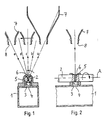
- the nozzle shaft 2 has a bore 6 which, according to the prior art, is perpendicular to its axis of rotation A.
- the end of the bore 6 toward the spray tube 1, which is towards the spray tube 1 is connected to the opening 4 over the angular range indicated in FIG. 1, so that liquid under the pressure in the spray tube 1 through the opening 4 and the bore 6 emerges in the form of a spray jet, which is shown in three swivel angles with the arrows a, c and e in FIG. 1.
- a bottle 7 with a mouth 8 is moved past, in the direction of the arrow according to FIG. 1.
- this corresponds to a movement perpendicular to the plane of the drawing.
- the rotary drive of the nozzle shaft 2 takes place synchronously with the transport movement of the bottle 7.
- the nozzle shaft rotates in the direction of rotation shown by an arrow in FIG. 1.
- the first jet a After opening of the bore 6 through the opening 4 of the spray tube 1, the first jet a thus hits the bottle at the angle shown.
- the last jet e shortly before the bore 6 is closed by the flange 3 strikes the bottle at an opposite oblique angle, which is then moved to the left in FIG. 1 so that the jet can still enter the mouth 8.
- the jet generated by the nozzle arrangement is pivoted in a plane perpendicular to the axis A of the nozzle shaft 2, 1 in the plane of the drawing.
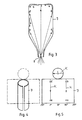
- FIG. 3 shows in the sectional plane of FIG. 1 the bottle 7 with the first incoming beam a, the central beam c incident vertically upwards, the last beam e and with two beams b and d in intermediate angular positions. It can be seen here that the points of incidence of the rays a to e first run upward on the right side wall of the bottle according to FIG. 3, then over the bottom of the bottle and then down again on the other side.
- the points of incidence of the rays a to e indicated in FIG. 3 are marked here.
- the first point of impact is at a, then runs vertically upwards on the side wall of the bottle via b to the bottom of the bottle, which it traverses in the center, the beam c striking the center of the bottom. Then the impact points d after e on the other side wall descend again.
- the angular positions 0 ° to 360 ° of the bottle shell with respect to the bottle axis are given below.
- the central plane of the bottle in which it is moved that is to say in the plane of the drawing according to FIGS. 1 and 3, runs through 0 ° and 180 °, as indicated in FIG. 3.
- the 0 ° position corresponds to the line of the bottle jacket, which lies at the front in the direction of movement of FIG. 1.
- the bore 6 is perpendicular to the axis of rotation A of the nozzle shaft 2.
- the spray jet a to e thus swings in the plane perpendicular to the axis of rotation A, that is to say in the plane of the drawing in FIGS. 1 and 3, that is to say in the central plane of the bottle 7, which according to FIG 5 runs through 0 ° and 180 °.
- FIGS. 1 to 2 the invention is explained in three exemplary embodiments, specifically on the basis of a spray tube construction with a nozzle shaft and bottles moved over it, corresponding to the construction of FIGS. 1 to 2, which is of completely identical design, except for the bore, which is designed differently is as the bore 6 of FIGS. 1 to 2.
- Fig. 6 shows a nozzle shaft 12 according to the invention in the direction of FIG. 2.
- the bore 16 is formed so that it emerges at both openings obliquely to the plane perpendicular to the axis of rotation A, that is, at both openings at the angle ⁇ shown compared to Axis A.
- This angle ⁇ can preferably be approximately 70 ° to 85 °.
- the spray jets emerging from the bore 16 therefore do not pivot in a plane perpendicular to the axis of rotation A, but in a flat cone with the axis of rotation A as the cone axis.
- the bottle 7 is transported in a slightly laterally offset transport path so that it can enter the mouth 8 via the swivel angle of the spray jet.
- FIG. 7 shows how the spray jets generated by the nozzle shaft 12 of FIG. 6 strike the bottle.
- the curve of these points of impact is denoted by K '.
- arrows also show the direction of travel of the rays lying against the wall. It turns out that apart from the jet pointing vertically upwards from point c, the jets all run more or less obliquely, that is to say run helically along the bottle wall.
- FIG. 7 shows, when the beam is swiveled from a to e, that is to say largely all areas of the Bottle detected by the rays running against the bottle wall. These rays run against the wall, as shown in FIG. 3 by means of the ray b. If one compares with the spray pattern of FIG. 5, it can be seen that in the spray pattern shown in FIG. 5 according to the prior art, the jets lying against the wall all run on the curve K. According to the invention, as can be seen from FIG. 7, the beams run helically in different directions and essentially cover the entire inner wall of the bottle.
- FIGS. 6 and 7 a variant of the embodiment of FIGS. 6 and 7 is shown.
- a bore 26 is provided in the nozzle shaft 22, in which the angle ⁇ (see FIG. 6) is larger, that is to say closer to 90 °.
- the curve K ⁇ of the spray jet impact points here runs somewhat slimmer than the curve K 'according to FIG. 7 and extends higher. The middle part of the curve runs over the ground.
- a comparison of FIGS. 7 and 9 shows how the spray pattern in the bottle can be changed by varying the angle ⁇ of the bores. Depending on the bottle shape (slim and long, thick and short), the spray pattern can be adapted to the requirements.
- FIG. 6 shows a nozzle shaft 32, which has two bores 36.1 and 36.2 at a distance on the axis of rotation A, each of which is symmetrically obliquely oriented in the opposite direction.
- the jets generated by these bores hit the same bottle 7.
- Fig. 12 shows the curves of the beam impact points in the development of the bottle.
- the rays generated by the bore 36.1 meet on the curve K 1 with the points of incidence a 1 to e 1.
- the rays of the bore 36.2 on the curve K2 with respect to the through 0 ° and 180 ° running center plane of the bottle is exactly symmetrical.
- FIG. 12 The particularly intensive spray pattern of FIG. 12 can be achieved instead of the construction of FIGS. 10 and 11 also with a construction of the nozzle shaft which is designed with only one bore in accordance with FIGS. 6 or 8. There are then two nozzle shafts to be arranged one behind the other on the transport path of the bottle, which spray in the opposite oblique direction. Then the one nozzle shaft (see Fig. 12) on the curve K 1 and the subsequent nozzle shaft on the curve K 2 spray.
- nozzle shafts are shown which preferably have a plurality of bores 16, 26 or pairs of bores 36.1, 36.2 over their length.
- Such nozzle shafts can be used in bottle cleaning machines of the usual type, in which in long bottles baskets bottles are moved in parallel on a large number of parallel bottle conveyors.
- a nozzle body with only one hole or a pair of holes is sufficient.
- nozzle body instead of rotating the nozzle body on a spray tube, it can also be stationary on it and pivoted with it, for example back and forth.
Landscapes
- Engineering & Computer Science (AREA)
- Mechanical Engineering (AREA)
- Cleaning In General (AREA)
- Spray Control Apparatus (AREA)
- Nozzles (AREA)
- Cleaning By Liquid Or Steam (AREA)
Applications Claiming Priority (2)
| Application Number | Priority Date | Filing Date | Title |
|---|---|---|---|
| DE3925725 | 1989-08-03 | ||
| DE3925725A DE3925725C2 (de) | 1989-08-03 | 1989-08-03 | Düsenanordnung zur Innenspritzung von Flaschen |
Publications (3)
| Publication Number | Publication Date |
|---|---|
| EP0411377A2 true EP0411377A2 (fr) | 1991-02-06 |
| EP0411377A3 EP0411377A3 (en) | 1992-08-05 |
| EP0411377B1 EP0411377B1 (fr) | 1996-01-03 |
Family
ID=6386460
Family Applications (1)
| Application Number | Title | Priority Date | Filing Date |
|---|---|---|---|
| EP90113573A Expired - Lifetime EP0411377B1 (fr) | 1989-08-03 | 1990-07-16 | Corps de buse pour le nettoyage intérieur des bouteilles |
Country Status (6)
| Country | Link |
|---|---|
| US (1) | US5092356A (fr) |
| EP (1) | EP0411377B1 (fr) |
| JP (1) | JPH0736904B2 (fr) |
| AT (1) | ATE132400T1 (fr) |
| DD (1) | DD296861A5 (fr) |
| DE (2) | DE3925725C2 (fr) |
Cited By (4)
| Publication number | Priority date | Publication date | Assignee | Title |
|---|---|---|---|---|
| WO2003084685A1 (fr) * | 2002-04-10 | 2003-10-16 | R. Bardi S.R.L. | Dispositif permettant de nettoyer l'interieur de contenant en plastique |
| EP1896329B2 (fr) † | 2005-06-24 | 2017-11-22 | Sidel Participations | Installation produisant des bouteilles steriles par soufflage a partir de preformes sterilisees |
| WO2018099650A1 (fr) * | 2016-11-30 | 2018-06-07 | Sig Technology Ag | Procédé et machine de remplissage pour le remplissage d'emballages ouverts d'un côté au travers d'une fente de buse allongée |
| WO2019048142A1 (fr) | 2017-09-09 | 2019-03-14 | Krones Ag | Dispositif et procédé de nettoyage de bouteilles |
Families Citing this family (15)
| Publication number | Priority date | Publication date | Assignee | Title |
|---|---|---|---|---|
| DE4216664C1 (de) * | 1992-05-20 | 1993-12-23 | Orthmann & Herbst | Spritzvorrichtung einer Flaschenreinigungsmaschine |
| DE4216665C1 (de) * | 1992-05-20 | 1993-12-23 | Orthmann & Herbst | Spritzvorrichtung für Flaschenreinigungsmaschinen |
| EP0576398B1 (fr) * | 1992-06-24 | 1998-05-13 | Vtz Engineering + Services Ag | Procédé, dispositif et machine pour le nettoyage des conteneurs qui sont ouverts sur un cÔté |
| US5419348A (en) * | 1993-07-12 | 1995-05-30 | Pepsico, Inc. | Nozzle spray assembly |
| DE4330335C2 (de) * | 1993-09-08 | 2003-08-21 | Krones Ag | Spritzvorrichtung für Flaschenreinigungsmaschinen |
| DE19714249A1 (de) * | 1997-04-07 | 1998-10-08 | Kronseder Maschf Krones | Verfahren und Vorrichtung zur Kontrolle der Innenraumbehandlung von Flaschen o. dgl. |
| DE10315866B4 (de) * | 2003-04-08 | 2019-04-25 | Krones Aktiengesellschaft | Spritzvorrichtung für Reinigungsmaschinen, insbesondere Flaschenreinigungsmaschinen |
| DE102007030220B4 (de) | 2007-06-29 | 2013-04-04 | Khs Gmbh | Spritzrohr sowie Spritzstation mit einem solchen Spritzrohr |
| JP5342263B2 (ja) * | 2009-02-13 | 2013-11-13 | 本田技研工業株式会社 | ノズル及び槽内異物除去装置 |
| DE102009039585A1 (de) * | 2009-09-01 | 2011-03-17 | Krones Ag | Spritzvorrichtung |
| EP3124128B8 (fr) | 2015-07-30 | 2022-04-06 | Sidel S.P.A. | Dispositif d'aspersion et unité de lavage correspondante |
| JP7716663B2 (ja) * | 2021-02-18 | 2025-08-01 | パナソニックIpマネジメント株式会社 | 洗浄機 |
| DE102021132313A1 (de) | 2021-12-08 | 2023-06-15 | Krones Aktiengesellschaft | Spritzvorrichtung und Verfahren zur Innenspritzung von Behältern |
| DE102023101236A1 (de) * | 2023-01-19 | 2024-07-25 | Krones Aktiengesellschaft | Vorrichtung und Verfahren zum Spülen des Innenraums eines Behälters |
| CN116422666B (zh) * | 2023-03-24 | 2025-09-23 | 上海北裕分析仪器股份有限公司 | 一种试瓶清洗装置 |
Family Cites Families (14)
| Publication number | Priority date | Publication date | Assignee | Title |
|---|---|---|---|---|
| US2004410A (en) * | 1931-03-09 | 1935-06-11 | Pako Corp | Apparatus for handling articles through treating liquids |
| FR991641A (fr) * | 1944-04-20 | 1951-10-08 | Organe de lavage, pour machines à laver les bouteilles et autres récipients | |
| US2763564A (en) * | 1953-11-25 | 1956-09-18 | Gen Electric | Means and methods for processing cathode ray tube bulbs |
| US2851383A (en) * | 1953-12-22 | 1958-09-09 | Nat Gypsum Co | Air jet cleaning and nozzle for use therefor |
| FR1121809A (fr) * | 1955-04-05 | 1956-08-27 | Machine à laver les bouteilles et autres récipients similaires | |
| US2907688A (en) * | 1955-09-01 | 1959-10-06 | Philco Corp | Improved washing operation for cathode ray tube manufacturing process |
| DE1031163B (de) * | 1956-10-24 | 1958-05-29 | Otto Tuchenhagen | Vorrichtung zum Reinigen von Behaeltern fuer Nahrungsmittel |
| NZ182304A (en) * | 1975-10-22 | 1979-03-28 | Oag Ej | Bottle cleaning apparatus:first conveyor carries cradles for bottles,second conveyor supports nozzles for cleaning fluid |
| DE2607077C2 (de) * | 1976-02-21 | 1986-11-20 | Holstein Und Kappert Gmbh, 4600 Dortmund | Spritzvorrichtung für Flaschenreinigungsmaschinen |
| US4423745A (en) * | 1982-11-29 | 1984-01-03 | Simplimatic Engineering Company | Rinsing machine |
| DE3301525A1 (de) * | 1983-01-19 | 1984-07-19 | Heinz Oberurnen Hartnig | Reinigungsvorrichtung fuer einseitig offene behaeltnisse |
| DE3324825A1 (de) * | 1983-07-09 | 1985-01-17 | Behringwerke Ag, 3550 Marburg | Verfahren zum waschen der reaktionsgefaesse fuer immunologische tests |
| EP0134830B1 (fr) * | 1983-09-16 | 1987-01-28 | Holstein & Kappert GmbH | Buse de pulvérisation pour machine de nettoyage de bouteilles |
| DE3635213A1 (de) * | 1986-10-16 | 1988-04-28 | Kaercher Gmbh & Co Alfred | Fahrzeugwaschanlage |
-
1989
- 1989-08-03 DE DE3925725A patent/DE3925725C2/de not_active Expired - Fee Related
-
1990
- 1990-07-16 AT AT90113573T patent/ATE132400T1/de not_active IP Right Cessation
- 1990-07-16 EP EP90113573A patent/EP0411377B1/fr not_active Expired - Lifetime
- 1990-07-16 DE DE59010028T patent/DE59010028D1/de not_active Expired - Fee Related
- 1990-07-18 US US07/553,599 patent/US5092356A/en not_active Expired - Fee Related
- 1990-08-01 JP JP2202626A patent/JPH0736904B2/ja not_active Expired - Lifetime
- 1990-08-02 DD DD90343201A patent/DD296861A5/de not_active IP Right Cessation
Cited By (4)
| Publication number | Priority date | Publication date | Assignee | Title |
|---|---|---|---|---|
| WO2003084685A1 (fr) * | 2002-04-10 | 2003-10-16 | R. Bardi S.R.L. | Dispositif permettant de nettoyer l'interieur de contenant en plastique |
| EP1896329B2 (fr) † | 2005-06-24 | 2017-11-22 | Sidel Participations | Installation produisant des bouteilles steriles par soufflage a partir de preformes sterilisees |
| WO2018099650A1 (fr) * | 2016-11-30 | 2018-06-07 | Sig Technology Ag | Procédé et machine de remplissage pour le remplissage d'emballages ouverts d'un côté au travers d'une fente de buse allongée |
| WO2019048142A1 (fr) | 2017-09-09 | 2019-03-14 | Krones Ag | Dispositif et procédé de nettoyage de bouteilles |
Also Published As
| Publication number | Publication date |
|---|---|
| JPH0736904B2 (ja) | 1995-04-26 |
| DE59010028D1 (de) | 1996-02-15 |
| DD296861A5 (de) | 1991-12-19 |
| US5092356A (en) | 1992-03-03 |
| EP0411377A3 (en) | 1992-08-05 |
| EP0411377B1 (fr) | 1996-01-03 |
| DE3925725C2 (de) | 1996-04-11 |
| ATE132400T1 (de) | 1996-01-15 |
| DE3925725C1 (fr) | 1991-01-31 |
| JPH0380976A (ja) | 1991-04-05 |
Similar Documents
| Publication | Publication Date | Title |
|---|---|---|
| EP0411377B1 (fr) | Corps de buse pour le nettoyage intérieur des bouteilles | |
| EP1731081A2 (fr) | Lave-vaisselle | |
| DE102005026558B3 (de) | Geschirrspülmaschine mit einem Spülbehälter in dem wenigstens ein Sprüharm angeordnet ist | |
| DE1428424B2 (de) | Rotierende Sprühvorrichtung in Spul maschinen | |
| DE102009007297A1 (de) | Spülautomat mit einem quaderförmigen Spülraum | |
| DE102004062243A1 (de) | Geschirrspüler mit Ablenkblenden | |
| DE4330335C2 (de) | Spritzvorrichtung für Flaschenreinigungsmaschinen | |
| DE29718777U1 (de) | Geschirrspülmaschine mit verbesserten Sprüheinrichtungen | |
| DE19619773A1 (de) | Reinigungsvorrichtung | |
| EP1884588A2 (fr) | Dispositif de nettoyage | |
| EP2289640A1 (fr) | Dispositif de pulvérisation | |
| DE60308165T2 (de) | Verfahren zum waschen der innenflächen von kunststoffbehältern | |
| DE10315866B4 (de) | Spritzvorrichtung für Reinigungsmaschinen, insbesondere Flaschenreinigungsmaschinen | |
| DE10045932A1 (de) | Verfahren zur Spritzung und Spritzvorrichtung an einer Flaschenreinigungsmaschine | |
| DE1237969B (de) | Duese zur Fass- oder Gefaessreinigung | |
| DE4005094A1 (de) | Schaeumvorrichtung | |
| DE202005021574U1 (de) | Behälterreinigungsvorrichtung | |
| WO2021151698A1 (fr) | Dispositif et procédé d'application d'un fluide de nettoyage sur un élément de véhicule | |
| DE2639453A1 (de) | Rotations-reinigungsvorrichtung | |
| DE2226894A1 (de) | Spuelmaschine | |
| WO2023117615A1 (fr) | Dispositif de nettoyage | |
| WO2026017681A1 (fr) | Lave-vaisselle | |
| EP0403794B1 (fr) | Buse de pulvérisation pour machine de nettoyage de bouteilles | |
| EP1382287A2 (fr) | Dispositif d'arrosage pour un lave-vaisselle automatique | |
| DE202011108598U1 (de) | Schutzkorb für eine Behälterreinigungsvorrichtung |
Legal Events
| Date | Code | Title | Description |
|---|---|---|---|
| PUAI | Public reference made under article 153(3) epc to a published international application that has entered the european phase |
Free format text: ORIGINAL CODE: 0009012 |
|
| AK | Designated contracting states |
Kind code of ref document: A2 Designated state(s): AT BE CH DE DK ES FR GB GR IT LI LU NL SE |
|
| 17P | Request for examination filed |
Effective date: 19901221 |
|
| RAP1 | Party data changed (applicant data changed or rights of an application transferred) |
Owner name: APV ORTMANN + HERBST GMBH |
|
| PUAL | Search report despatched |
Free format text: ORIGINAL CODE: 0009013 |
|
| AK | Designated contracting states |
Kind code of ref document: A3 Designated state(s): AT BE CH DE DK ES FR GB GR IT LI LU NL SE |
|
| 17Q | First examination report despatched |
Effective date: 19930929 |
|
| RAP1 | Party data changed (applicant data changed or rights of an application transferred) |
Owner name: ORTMANN + HERBST MASCHINEN- UND ANLAGENBAU GMBH |
|
| GRAA | (expected) grant |
Free format text: ORIGINAL CODE: 0009210 |
|
| AK | Designated contracting states |
Kind code of ref document: B1 Designated state(s): AT BE CH DE DK ES FR GB GR IT LI LU NL SE |
|
| PG25 | Lapsed in a contracting state [announced via postgrant information from national office to epo] |
Ref country code: NL Free format text: LAPSE BECAUSE OF FAILURE TO SUBMIT A TRANSLATION OF THE DESCRIPTION OR TO PAY THE FEE WITHIN THE PRESCRIBED TIME-LIMIT Effective date: 19960103 Ref country code: GR Free format text: LAPSE BECAUSE OF FAILURE TO SUBMIT A TRANSLATION OF THE DESCRIPTION OR TO PAY THE FEE WITHIN THE PRESCRIBED TIME-LIMIT Effective date: 19960103 Ref country code: ES Free format text: THE PATENT HAS BEEN ANNULLED BY A DECISION OF A NATIONAL AUTHORITY Effective date: 19960103 Ref country code: DK Effective date: 19960103 Ref country code: BE Effective date: 19960103 |
|
| REF | Corresponds to: |
Ref document number: 132400 Country of ref document: AT Date of ref document: 19960115 Kind code of ref document: T |
|
| REF | Corresponds to: |
Ref document number: 59010028 Country of ref document: DE Date of ref document: 19960215 |
|
| ET | Fr: translation filed | ||
| GBT | Gb: translation of ep patent filed (gb section 77(6)(a)/1977) |
Effective date: 19960219 |
|
| ITF | It: translation for a ep patent filed | ||
| PG25 | Lapsed in a contracting state [announced via postgrant information from national office to epo] |
Ref country code: SE Effective date: 19960403 |
|
| NLV1 | Nl: lapsed or annulled due to failure to fulfill the requirements of art. 29p and 29m of the patents act | ||
| PG25 | Lapsed in a contracting state [announced via postgrant information from national office to epo] |
Ref country code: GB Effective date: 19960716 Ref country code: AT Effective date: 19960716 |
|
| PG25 | Lapsed in a contracting state [announced via postgrant information from national office to epo] |
Ref country code: LU Free format text: LAPSE BECAUSE OF NON-PAYMENT OF DUE FEES Effective date: 19960731 Ref country code: LI Effective date: 19960731 Ref country code: CH Effective date: 19960731 |
|
| PLBE | No opposition filed within time limit |
Free format text: ORIGINAL CODE: 0009261 |
|
| STAA | Information on the status of an ep patent application or granted ep patent |
Free format text: STATUS: NO OPPOSITION FILED WITHIN TIME LIMIT |
|
| 26N | No opposition filed | ||
| GBPC | Gb: european patent ceased through non-payment of renewal fee |
Effective date: 19960716 |
|
| REG | Reference to a national code |
Ref country code: FR Ref legal event code: ST |
|
| REG | Reference to a national code |
Ref country code: FR Ref legal event code: RN |
|
| REG | Reference to a national code |
Ref country code: FR Ref legal event code: FC |
|
| PGFP | Annual fee paid to national office [announced via postgrant information from national office to epo] |
Ref country code: DE Payment date: 19990527 Year of fee payment: 10 |
|
| PG25 | Lapsed in a contracting state [announced via postgrant information from national office to epo] |
Ref country code: DE Free format text: LAPSE BECAUSE OF NON-PAYMENT OF DUE FEES Effective date: 20010501 |
|
| PGFP | Annual fee paid to national office [announced via postgrant information from national office to epo] |
Ref country code: FR Payment date: 20010730 Year of fee payment: 12 |
|
| PG25 | Lapsed in a contracting state [announced via postgrant information from national office to epo] |
Ref country code: FR Free format text: LAPSE BECAUSE OF NON-PAYMENT OF DUE FEES Effective date: 20030331 |
|
| REG | Reference to a national code |
Ref country code: FR Ref legal event code: ST |
|
| PG25 | Lapsed in a contracting state [announced via postgrant information from national office to epo] |
Ref country code: IT Free format text: LAPSE BECAUSE OF NON-PAYMENT OF DUE FEES;WARNING: LAPSES OF ITALIAN PATENTS WITH EFFECTIVE DATE BEFORE 2007 MAY HAVE OCCURRED AT ANY TIME BEFORE 2007. THE CORRECT EFFECTIVE DATE MAY BE DIFFERENT FROM THE ONE RECORDED. Effective date: 20050716 |