EP0411444A2 - Procédé pour ménager des rainures dans les enveloppes des rouleaux et un rouleau traité selon ce procédÀ© - Google Patents
Procédé pour ménager des rainures dans les enveloppes des rouleaux et un rouleau traité selon ce procédÀ© Download PDFInfo
- Publication number
- EP0411444A2 EP0411444A2 EP90114181A EP90114181A EP0411444A2 EP 0411444 A2 EP0411444 A2 EP 0411444A2 EP 90114181 A EP90114181 A EP 90114181A EP 90114181 A EP90114181 A EP 90114181A EP 0411444 A2 EP0411444 A2 EP 0411444A2
- Authority
- EP
- European Patent Office
- Prior art keywords
- roller
- grooves
- laser beam
- groove
- compressed gas
- Prior art date
- Legal status (The legal status is an assumption and is not a legal conclusion. Google has not performed a legal analysis and makes no representation as to the accuracy of the status listed.)
- Withdrawn
Links
- 238000000034 method Methods 0.000 title claims abstract description 33
- 239000000463 material Substances 0.000 claims abstract description 11
- 239000007789 gas Substances 0.000 claims description 20
- 239000000203 mixture Substances 0.000 claims description 6
- 230000001590 oxidative effect Effects 0.000 claims description 4
- 239000011261 inert gas Substances 0.000 claims description 2
- 238000004519 manufacturing process Methods 0.000 claims description 2
- 229910001220 stainless steel Inorganic materials 0.000 description 5
- 239000010935 stainless steel Substances 0.000 description 5
- 230000000694 effects Effects 0.000 description 4
- 241001504664 Crossocheilus latius Species 0.000 description 2
- 238000006073 displacement reaction Methods 0.000 description 2
- 238000002844 melting Methods 0.000 description 2
- 230000008018 melting Effects 0.000 description 2
- 239000002184 metal Substances 0.000 description 2
- 230000001681 protective effect Effects 0.000 description 2
- 239000007787 solid Substances 0.000 description 2
- XLYOFNOQVPJJNP-UHFFFAOYSA-N water Substances O XLYOFNOQVPJJNP-UHFFFAOYSA-N 0.000 description 2
- QVGXLLKOCUKJST-UHFFFAOYSA-N atomic oxygen Chemical compound [O] QVGXLLKOCUKJST-UHFFFAOYSA-N 0.000 description 1
- 238000007664 blowing Methods 0.000 description 1
- 238000001816 cooling Methods 0.000 description 1
- 238000005260 corrosion Methods 0.000 description 1
- 230000007797 corrosion Effects 0.000 description 1
- 230000003247 decreasing effect Effects 0.000 description 1
- 238000001035 drying Methods 0.000 description 1
- 238000005516 engineering process Methods 0.000 description 1
- 239000000835 fiber Substances 0.000 description 1
- 238000010438 heat treatment Methods 0.000 description 1
- 238000003754 machining Methods 0.000 description 1
- 238000003701 mechanical milling Methods 0.000 description 1
- 239000000155 melt Substances 0.000 description 1
- 230000003647 oxidation Effects 0.000 description 1
- 238000007254 oxidation reaction Methods 0.000 description 1
- 239000001301 oxygen Substances 0.000 description 1
- 229910052760 oxygen Inorganic materials 0.000 description 1
- 230000035515 penetration Effects 0.000 description 1
- 230000008092 positive effect Effects 0.000 description 1
- 230000001105 regulatory effect Effects 0.000 description 1
- 238000004904 shortening Methods 0.000 description 1
- 239000007858 starting material Substances 0.000 description 1
- 238000004804 winding Methods 0.000 description 1
Images
Classifications
-
- B—PERFORMING OPERATIONS; TRANSPORTING
- B23—MACHINE TOOLS; METAL-WORKING NOT OTHERWISE PROVIDED FOR
- B23K—SOLDERING OR UNSOLDERING; WELDING; CLADDING OR PLATING BY SOLDERING OR WELDING; CUTTING BY APPLYING HEAT LOCALLY, e.g. FLAME CUTTING; WORKING BY LASER BEAM
- B23K26/00—Working by laser beam, e.g. welding, cutting or boring
- B23K26/08—Devices involving relative movement between laser beam and workpiece
- B23K26/0823—Devices involving rotation of the workpiece
-
- D—TEXTILES; PAPER
- D21—PAPER-MAKING; PRODUCTION OF CELLULOSE
- D21F—PAPER-MAKING MACHINES; METHODS OF PRODUCING PAPER THEREON
- D21F3/00—Press section of machines for making continuous webs of paper
- D21F3/02—Wet presses
- D21F3/08—Pressure rolls
- D21F3/086—Pressure rolls having a grooved surface
Definitions
- the present invention relates to a method for introducing drainage grooves in the surface of a roller, which for processing web-like materials, for. As paper, is suitable, and a roller processed by this method.
- a water-fiber mixture with a solids content of approx. 2% is applied to an endlessly rotating sieve. A large part of the water flows through the sieve openings, so that after a short time the solids content increases to approx. 50%.
- the paper web which is still not very firm, is transferred to an endlessly circulating felt.
- the paper web and felt are passed together through the so-called wet press.
- wet press are two- or multi-roll mills, e.g. B. consisting of a stone roller with one or more pressure rollers. While the stone roller on the paper side is smooth, the pressure rollers on the felt side are mostly grooved.
- grooved rollers are made with a stainless steel cover.
- An alternative method of applying a grooved stainless steel cover is to wrap a prepared roll body with a specially shaped stainless steel band.
- the profile of this band has a height of approximately 12 mm and a thickness in the area of the groove which corresponds to the web between the grooves.
- the profile is as wide as the bridge plus groove. If the stainless steel strip is then wound onto the roll body under tension and pressure, a helically grooved roll surface is created. Since the starting material is expensive, this process is also very complex.
- the present invention is intended to remedy the disadvantages of the prior art listed above and, in particular, to propose a method with which various groove shapes can be formed in the surface of such a roller without great effort.
- the focused light beam from a laser source is directed onto the surface of a roller to be grooved.
- the laser beam very quickly melts a limited area of the surface.
- the melted material is blown away by blowing on the melting point using a directed compressed gas jet. If the roller is now turned, a groove is created. If you simultaneously move the laser source in the axial direction to the roller, a helical groove is created.
- the shape, depth and course of the groove can be set, just as it is for. B. is required to optimize the dewatering effect of the exemplified press roll.
- a protective gas atmosphere in the area to be processed on the surface of the roller, which, for. B. prevents the oxidation of the edge areas, whereby the edge quality of the grooves can be improved.
- the pressurized gas jet only needs to consist of inert gases.
- the grooves should never be burned deeper into the roll shell than 10 mm.
- the groove depth is preferably in a range between 3 and 7 mm, a groove depth of 5 mm usually being used.
- the grooves that are created in the roll shell using the laser beam should not be wider than 1 mm, preferably 0.3 to 0.7 mm wide. As a rule, grooves with a width of 0.5 mm are produced.
- CO2 laser is particularly expedient in the present case, since its technology is mature and tried and tested.
- Other types of lasers can also be used.
- lasers with energy densities of at least 1 kW, preferably at least 5 kW, should be used to carry out the method according to the invention.
- the roller to be machined is located in a holder in which the roller can be rotated about its axis of rotation at a specific, uniform speed.
- the laser beam In order to achieve the desired groove depth, the laser beam must have a certain dwell time in a defined area on the roller surface. This required dwell time is taken into account by an appropriately set rotation speed of the roller. The necessary dwell time can of course also be regulated via the energy density of the laser beam.
- the working laser source or the laser beam can be moved along the roller to be processed.
- the speed at which this Movement takes place results in connection with the speed of rotation of the roller a certain slope for the helical groove to be created.
- the pitch of the helical groove should be such that the distance between two adjacent groove channels is not greater than 10 mm and preferably 5 mm.
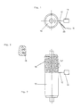
- Fig. 1 shows schematically a basic arrangement for performing the method according to the invention.
- a roller 10 which is rotatable and / or displaceable in a holder in the direction of the arrow, is processed by means of a laser beam 12.
- the laser beam 12 is generated by a laser source 14.
- a CO2 laser is preferably used as the laser source 14.
- a protective gas atmosphere or an oxidizing atmosphere can be generated on the roller surface in the area to be processed via a feed pipe or a cannula 20. If the assistive gas is directed at the surface of the roller to be machined at high pressure, the gas flow simultaneously blows away the melted, vaporized or burned materials from the resulting groove and from the working area of the laser beam 12 on the roller surface.
- the roller 10 is rotated at a certain speed and at the same time axially displaced.
- the dwell time of the laser beam 12 at a specific point on the roller surface can be influenced by the rotational speed of the roller.
- the depth of the drainage grooves in the roller surface of the roller 10 can be defined by varying the rotational speed.
- the roller 10 should not be rotated so slowly that the groove depth becomes greater than 10 mm.
- the groove depth should preferably be between 3 and 7 mm, generally 5 mm.
- the laser beam 12 should act on the surface of the roller 10 over a width of at most 1 mm, preferably 0.3 to 0.7 mm. As a rule, the laser beam 12 should vaporize the material of the roller surface over a width of 0.5 mm and thus create a groove width of 0.5 mm.
- the lateral distance between two adjacent groove channels is determined by the displacement of the roller in the axial direction.
- the maximum axial displacement speed of the roller 10 should not create a greater distance between two adjacent groove channels 18 than a maximum of 10 mm, preferably approximately 5 mm.
- the groove depth can also be adjusted by increasing or decreasing the intensity of the laser beam 12 while the roller 10 is rotating at a constant speed.
- All movements can be carried out exclusively by the roller 10, but also exclusively by the laser (or laser beam).
- the roller 10 will preferably perform the rotational movement, while the laser beam 12 or the laser source 14 executes the axial movement along the axis of the roller 10.
- FIG. 2 shows a schematic, basic illustration of the arrangement according to FIG. 1, but in a top view.
- the helical shape of the groove 18 can be clearly seen.
- the groove 18 can also consist of opposing helical grooves 18 which overlap.
- the laser source 14 is adjusted so that the laser beam 12 strikes the roller surface perpendicularly.
- the laser source 14 can also be adjusted in an application-oriented manner in such a way that the laser beam 12 strikes the roller surface at a certain angle between 90 and approximately 0 °.
- FIG. 3 shows the detail "X" of FIG. 2 on an enlarged scale.
- the grooves 18 which have been produced by the method according to the invention can be clearly seen.
- the drainage grooves 18 can also be given a course that is not perpendicular to the surface of the roller.
Landscapes
- Physics & Mathematics (AREA)
- Optics & Photonics (AREA)
- Engineering & Computer Science (AREA)
- Plasma & Fusion (AREA)
- Mechanical Engineering (AREA)
- Laser Beam Processing (AREA)
- Paper (AREA)
Applications Claiming Priority (2)
| Application Number | Priority Date | Filing Date | Title |
|---|---|---|---|
| DE3925787A DE3925787A1 (de) | 1989-08-03 | 1989-08-03 | Verfahren zum einbringen von rillen in walzenoberflaechen, sowie eine nach diesem verfahren bearbeitete walze |
| DE3925787 | 1989-08-03 |
Publications (2)
| Publication Number | Publication Date |
|---|---|
| EP0411444A2 true EP0411444A2 (fr) | 1991-02-06 |
| EP0411444A3 EP0411444A3 (en) | 1991-09-11 |
Family
ID=6386489
Family Applications (1)
| Application Number | Title | Priority Date | Filing Date |
|---|---|---|---|
| EP19900114181 Withdrawn EP0411444A3 (en) | 1989-08-03 | 1990-07-24 | Process for grooving roll surfaces and a roll treated according to this process |
Country Status (5)
| Country | Link |
|---|---|
| EP (1) | EP0411444A3 (fr) |
| JP (1) | JPH03142093A (fr) |
| CA (1) | CA2022366A1 (fr) |
| DE (1) | DE3925787A1 (fr) |
| FI (1) | FI903822A7 (fr) |
Cited By (1)
| Publication number | Priority date | Publication date | Assignee | Title |
|---|---|---|---|---|
| CN110578265A (zh) * | 2018-06-11 | 2019-12-17 | 福伊特专利有限公司 | 沟槽式的伏辊和包括所述伏辊的装置 |
Families Citing this family (2)
| Publication number | Priority date | Publication date | Assignee | Title |
|---|---|---|---|---|
| JP5283124B2 (ja) * | 2009-07-24 | 2013-09-04 | 独立行政法人産業技術総合研究所 | 電解,レーザ複合加工方法及び装置 |
| JP5406732B2 (ja) * | 2010-01-12 | 2014-02-05 | 大王製紙株式会社 | 抄紙工程用セラミックロール |
Family Cites Families (5)
| Publication number | Priority date | Publication date | Assignee | Title |
|---|---|---|---|---|
| NO129688C (fr) * | 1963-02-14 | 1976-12-14 | Beloit Corp | |
| US3597578A (en) * | 1967-03-16 | 1971-08-03 | Nat Res Dev | Thermal cutting apparatus and method |
| JPS5469896A (en) * | 1977-11-15 | 1979-06-05 | Koyo Seiko Co Ltd | Method of machining work outer surface with laser beam |
| DE3708605A1 (de) * | 1987-03-17 | 1988-09-29 | Boettcher Gmbh & Co Felix | Presswalze fuer die entwaesserung von stoffbahnen |
| DE3923719A1 (de) * | 1989-05-20 | 1990-11-29 | Man Technologie Gmbh | Verfahren und vorrichtung zum abtragen von material aus werkstuecken |
-
1989
- 1989-08-03 DE DE3925787A patent/DE3925787A1/de not_active Withdrawn
-
1990
- 1990-07-24 EP EP19900114181 patent/EP0411444A3/de not_active Withdrawn
- 1990-07-31 FI FI903822A patent/FI903822A7/fi not_active IP Right Cessation
- 1990-07-31 CA CA002022366A patent/CA2022366A1/fr not_active Abandoned
- 1990-08-03 JP JP2207483A patent/JPH03142093A/ja active Pending
Cited By (1)
| Publication number | Priority date | Publication date | Assignee | Title |
|---|---|---|---|---|
| CN110578265A (zh) * | 2018-06-11 | 2019-12-17 | 福伊特专利有限公司 | 沟槽式的伏辊和包括所述伏辊的装置 |
Also Published As
| Publication number | Publication date |
|---|---|
| DE3925787A1 (de) | 1991-02-07 |
| CA2022366A1 (fr) | 1991-02-04 |
| JPH03142093A (ja) | 1991-06-17 |
| EP0411444A3 (en) | 1991-09-11 |
| FI903822A0 (fi) | 1990-07-31 |
| FI903822A7 (fi) | 1991-02-04 |
Similar Documents
| Publication | Publication Date | Title |
|---|---|---|
| DE3881906T2 (de) | Verfahren zur Oberflächenmarkierung von Walzwerkswalzen. | |
| DE69520861T2 (de) | Gerät zur Herstellung von Vliesstoffen mit Reliefmustern | |
| EP0802277A2 (fr) | Machine pour la fabrication d'une bande de matériau | |
| DE3100927A1 (de) | Verfahren zur bearbeitung der oberflaeche einer walze fuer kaltwalzen, insbesondere einer dressierwalze und vorrichtung zur durchfuehrung dieses verfahrens | |
| DE2522965A1 (de) | Vorrichtung in einer papiermaschine zur verbesserung der glaette und des glanzes der papier- oder pappoberflaeche | |
| DE10258324B4 (de) | Verfahren zur Herstellung von Garnituren für das Mahlen von wasserhaltigem Papierfaserstoff | |
| DE4206002A1 (de) | Verfahren zum erzeugen eines musters in der oberflaeche eines werkstuecks | |
| EP0411444A2 (fr) | Procédé pour ménager des rainures dans les enveloppes des rouleaux et un rouleau traité selon ce procédÀ© | |
| DE2339552B2 (de) | Verfahren und Vorrichtung zum Kühlen von mittels großer Wärmezufuhr erzeugter Schweißungen | |
| WO2004065083A1 (fr) | Systeme de decoupe par jet d'eau | |
| US5351399A (en) | Method for forming grooves in roll surfaces | |
| EP1660709B1 (fr) | Procede de retrecissement par compression et installation de retrecissement au moyen d'une toile caoutchoutee | |
| DE3031217C2 (de) | Verfahren und Vorrichtung zum Trocknen eines Furnierblattes | |
| CH340700A (de) | Verfahren zum Perforieren von Papier und Einrichtung zur Durchführung dieses Verfahrens | |
| DE3311933A1 (de) | Anordnung zur waermebehandlung eines papiermaschinensiebes oder -filzes | |
| DE3715554C2 (fr) | ||
| DE2638304C3 (de) | Düse zum Maschinenflämmen von Einzelfehlern | |
| EP1784277B1 (fr) | Procede de soudage par recouvrement par rayonnement, notamment par rayons laser, sur des toles enduites, notamment des toles d'acier galvanise | |
| DE2708434A1 (de) | Verfahren und vorrichtung zur herstellung von durchbruechen in bandmaterial | |
| DE2307319C3 (de) | Verfahren zum streifenweisen Flammhobeln von Metallflächen | |
| EP1392929B1 (fr) | Coeur de croisement pour aiguillages et son procede de realisation | |
| AT255884B (de) | Verfahren und Vorrichtung zum Herstellen einer ein- oder beidseitig geglätteten Papierbahh od. dgl. | |
| DE3050278C2 (de) | Verfahren und Vorrichtung zum Plasmalichtbogenumschmelzen der Oberfl{chenschicht eines flachen Metallwerkst}cks | |
| AT387248B (de) | Mit einem waermetraegermedium, insbesondere dampf, beheizbarer zylinder | |
| EP1371776A2 (fr) | Calandre et procédé pour le fonctionnement d' un calandre |
Legal Events
| Date | Code | Title | Description |
|---|---|---|---|
| PUAI | Public reference made under article 153(3) epc to a published international application that has entered the european phase |
Free format text: ORIGINAL CODE: 0009012 |
|
| AK | Designated contracting states |
Kind code of ref document: A2 Designated state(s): CH DE GB IT LI |
|
| PUAL | Search report despatched |
Free format text: ORIGINAL CODE: 0009013 |
|
| AK | Designated contracting states |
Kind code of ref document: A3 Designated state(s): CH DE GB IT LI |
|
| 17P | Request for examination filed |
Effective date: 19920219 |
|
| STAA | Information on the status of an ep patent application or granted ep patent |
Free format text: STATUS: THE APPLICATION HAS BEEN WITHDRAWN |
|
| 18W | Application withdrawn |
Withdrawal date: 19930827 |