EP0411457A1 - Türblatt - Google Patents
Türblatt Download PDFInfo
- Publication number
- EP0411457A1 EP0411457A1 EP90114248A EP90114248A EP0411457A1 EP 0411457 A1 EP0411457 A1 EP 0411457A1 EP 90114248 A EP90114248 A EP 90114248A EP 90114248 A EP90114248 A EP 90114248A EP 0411457 A1 EP0411457 A1 EP 0411457A1
- Authority
- EP
- European Patent Office
- Prior art keywords
- tubes
- metal
- door leaf
- chipboard
- metal tubes
- Prior art date
- Legal status (The legal status is an assumption and is not a legal conclusion. Google has not performed a legal analysis and makes no representation as to the accuracy of the status listed.)
- Granted
Links
Images
Classifications
-
- E—FIXED CONSTRUCTIONS
- E06—DOORS, WINDOWS, SHUTTERS, OR ROLLER BLINDS IN GENERAL; LADDERS
- E06B—FIXED OR MOVABLE CLOSURES FOR OPENINGS IN BUILDINGS, VEHICLES, FENCES OR LIKE ENCLOSURES IN GENERAL, e.g. DOORS, WINDOWS, BLINDS, GATES
- E06B5/00—Doors, windows, or like closures for special purposes; Border constructions therefor
- E06B5/10—Doors, windows, or like closures for special purposes; Border constructions therefor for protection against air-raid or other war-like action; for other protective purposes
- E06B5/16—Fireproof doors or similar closures; Adaptations of fixed constructions therefor
- E06B5/161—Profile members therefor
-
- E—FIXED CONSTRUCTIONS
- E06—DOORS, WINDOWS, SHUTTERS, OR ROLLER BLINDS IN GENERAL; LADDERS
- E06B—FIXED OR MOVABLE CLOSURES FOR OPENINGS IN BUILDINGS, VEHICLES, FENCES OR LIKE ENCLOSURES IN GENERAL, e.g. DOORS, WINDOWS, BLINDS, GATES
- E06B5/00—Doors, windows, or like closures for special purposes; Border constructions therefor
- E06B5/10—Doors, windows, or like closures for special purposes; Border constructions therefor for protection against air-raid or other war-like action; for other protective purposes
- E06B5/11—Doors, windows, or like closures for special purposes; Border constructions therefor for protection against air-raid or other war-like action; for other protective purposes against burglary
-
- E—FIXED CONSTRUCTIONS
- E06—DOORS, WINDOWS, SHUTTERS, OR ROLLER BLINDS IN GENERAL; LADDERS
- E06B—FIXED OR MOVABLE CLOSURES FOR OPENINGS IN BUILDINGS, VEHICLES, FENCES OR LIKE ENCLOSURES IN GENERAL, e.g. DOORS, WINDOWS, BLINDS, GATES
- E06B5/00—Doors, windows, or like closures for special purposes; Border constructions therefor
- E06B5/10—Doors, windows, or like closures for special purposes; Border constructions therefor for protection against air-raid or other war-like action; for other protective purposes
- E06B5/16—Fireproof doors or similar closures; Adaptations of fixed constructions therefor
-
- E—FIXED CONSTRUCTIONS
- E06—DOORS, WINDOWS, SHUTTERS, OR ROLLER BLINDS IN GENERAL; LADDERS
- E06B—FIXED OR MOVABLE CLOSURES FOR OPENINGS IN BUILDINGS, VEHICLES, FENCES OR LIKE ENCLOSURES IN GENERAL, e.g. DOORS, WINDOWS, BLINDS, GATES
- E06B3/00—Window sashes, door leaves, or like elements for closing wall or like openings; Layout of fixed or moving closures, e.g. windows in wall or like openings; Features of rigidly-mounted outer frames relating to the mounting of wing frames
- E06B3/70—Door leaves
- E06B2003/7059—Specific frame characteristics
- E06B2003/7061—Wooden frames
- E06B2003/7073—Wooden frames with fire retardant measures in frame
Definitions
- the invention relates to a door leaf according to the preamble of patent claim 1.
- a door leaf according to the preamble of claim 1 is known from EP 141 368. With this door leaf, metal elements in the form of metal bars are used in at least some of the tubes of the chipboard, which ensures sufficient security against break-ins.
- a security door leaf made of wood in which transverse or vertical bars or tubes are arranged between the outer door leaf surfaces, ie inside the door leaf. These rods or tubes, which may also be provided in a crosswise manner, are received in bores formed opposite one another.
- the invention has for its object to design a door leaf according to the preamble of claim 1 such that the highest possible transverse stiffening is achieved.
- the door leaf consists of a commercially available chipboard, in which the individual tubes running in the transverse direction have a predetermined, preferably fixed center-to-center distance. It has been shown that the use of metal tubes, for example iron tubes, in at least some of the tubes of the particle board brings about an extraordinarily strong improvement in the bending moment, i. H. a very high bending moment is obtained, and thus the breakthrough-inhibiting property of such a door leaf is surprisingly greatly improved.
- the metal tubes preferably iron tubes
- the metal tubes are preferably inserted into every second or preferably every third tube of the chipboard, the outer diameter of the iron tubes being slightly smaller than the inside diameter of the tubes of the chipboard.
- the transverse tubes of the chipboard are at least partially filled with iron pipes.
- the use of the iron tubes surprisingly leads to a very high transverse stiffening of the door leaf in that the iron tubes lie close to the inner wall of the tubes of the chipboard and practically a bond between the iron tube and the chipboard is produced.
- the inherent stiffness of iron pipes compared to metal bars also contributes significantly to the high static transverse stiffening of such a door leaf.
- the metal pipes can be filled with a fire-retardant material, a fire extinguishing powder or the like and / or additionally contain metal rods. Additionally provided metal rods within the metal pipes lead to a higher resistance to saw cuts.
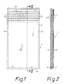
- Fig. 1 is a schematic representation of a door leaf having a tubular chipboard 1 and a peripheral frame 2.
- the frame 2 enclosing the tubular chipboard on its narrow side consists, for example, of wood or metal.
- the chipboard 1 contains in a manner known per se in the transverse direction, i. H. horizontally extending tubes 3, 6.
- the tubes 3, 6 extend in the transverse direction or in the horizontal direction through the particle board in each case between the side frame sections 2a, 2b surrounding them laterally.
- the tubes lying vertically one above the other according to FIG. 2 have a uniform spacing from one another and a center-to-center spacing of, for example, 27 mm, each tube has a diameter of, for example, 22 mm.
- the tubes 3, 6 of the tube chipboard thus form a plurality of cylindrical cavities in inside the door leaf.
- the door leaf can be surrounded by a metal frame, which is formed by mutually parallel legs 7, 8, which run along the outer surface of the door leaf, as is indicated by dashed lines in FIG. 2.
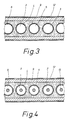
- the tubes 3, 6 are at least partially provided with metal tubes, as illustrated in FIG. 3.
- the metal tubes are shown with reference number 4.
- all tubes 3, 6 are filled with metal tubes 4, while according to a further embodiment every second tube or according to a further embodiment only every third tube of the chipboard 1 is provided with the metal tubes 4.
- the outer diameter of the metal tubes 4 inserted into the tubes 3 and / or 6 of the chipboard 1 is slightly smaller than the inner diameter of the tubes 3, 6. This ensures that the metal tubes 4 lie closely against the inner wall of the tubes 3 and / or 6 and cause stabilization of the chipboard 1.
- the outside diameter of the metal tubes 4 is preferably 5/10 mm smaller than the inside diameter of the tubes 3, 6 of the chipboard 1. According to a preferred embodiment, the outside diameter of the metal tubes 4 is 19 mm compared to an inside diameter of 22 mm of the chipboard 1.
- the tubular chipboard 1 shown in FIG. 3 is provided in a manner known per se on the broad sides with a layer, preferably in the form of a fiber plate 9, which can be coated with a veneer 12 or another layer facing the outside.
- the static transverse stiffening of a door leaf is extremely increased by the use of the metal tubes 4, which leads to a very high bending moment.
- the breakthrough-inhibiting property of the door leaves is significantly improved.
- the remaining cavities i. H. the cavity defined by the metal tubes 4 inside the chipboard can either be filled with a material 5, which for example has a fire-retardant property, or metal rods 15 can additionally be provided within the metal tubes 4, as is illustrated by the particle view according to FIG. 4.
- the metal rods 15 additionally arranged within the metal tubes 4 serve to further improve the breakthrough-inhibiting properties and are preferably used concentrically with the metal tubes 4. The concentric arrangement of the rods 15 is facilitated if the space between the metal tube 4 and rod 15 with a filling material, for. B. fire retardant material is filled.
- metal tubes which have a wall thickness of 1 mm.
- the wall thickness of the metal tubes 4 can obviously be chosen larger, but at the same time accepting an increase in the weight of the entire door leaf.
- Manganese steels are preferably used as steel rods 15.
- the iron tubes are preferably inserted into the tubes of the chipboard 1 before the door blank is glued together. When using a wooden frame 2, this is after inserting the iron pipes 4 on the door blank in the area thereof Narrow sides applied and glued to the door blank.
- a metal frame is used as the frame 2, which has the profiling described in connection with FIG. 2 with the legs 7, 8.
- the metal tubes 4 are preferably attached to the metal frame part 2a in the manner of a comb, for example by welding.
- the metal tubes 4 together with the strip-shaped frame part 2a as a unit can be inserted simultaneously into the associated tubes 3 and / or 6 of the chipboard 1. This takes place in that the door blank is rotated by 90 ° with respect to FIG. 1, as a result of which the tubes 3, 6 of the tube chipboard 1 come to lie in the vertical direction.
- the unit consisting of the metal frame part 2a and the metal tubes 4 can then simply be moved into the door blank from above.
- the rods 15 are preferably also firmly connected to the frame part 2a and thus simultaneously inserted into the door leaf with the metal tubes 4. According to a further alternative, the rods 15 are inserted separately and after the metal tubes 4 have been introduced into the tubes of the chipboard 1.
Landscapes
- Engineering & Computer Science (AREA)
- Civil Engineering (AREA)
- Structural Engineering (AREA)
- Special Wing (AREA)
- Laminated Bodies (AREA)
- Liquid Crystal (AREA)
- Securing Of Glass Panes Or The Like (AREA)
- Patch Boards (AREA)
- Specific Sealing Or Ventilating Devices For Doors And Windows (AREA)
- Wing Frames And Configurations (AREA)
Abstract
Description
- Die Erfindung betrifft ein Türblatt gemäß dem Oberbegriff des Patentanspruchs 1.
- Ein Türblatt nach dem Oberbegriff des Patentanspruchs 1 ist aus der EP 141 368 bekannt. Bei diesem Türblatt sind zumindest in einem Teil der Röhren der Röhrenspanplatte Metallelemente in Form von MNetallstäben eingesetzt, wodurch eine hinreichende Sicherheit gegenüber Einbrüchen gewährleistet ist.
- Aus dem DE-U-8 300 729 ist ein Sicherheitstürblatt aus Holz bekannt, bei dem quer oder senkrecht verlaufende Stäbe oder Rohre zwischen den Türblattaußenflächen, d. h. innerhalb des Türblattes angeordnet sind. Diese Stäbe oder Rohre, die gegebenenfalls auch kreuzweise verlaufend vorgesehen sind, werden in einander gegenüberliegenden Holmen ausgebildeten Bohrungen aufgenommen.
- Der Erfindung liegt die Aufgabe zugrunde, ein Türblatt gemäß dem Oberbegriff des Patentanspruchs 1 derart auszubilden, daß eine möglichst hohe Queraussteifung erreicht wird.
- Diese Aufgabe wird erfindungsgemäß durch die Merkmale des kennzeichnenden Teils des Patentanspruchs 1 erreicht .
- Weitere Ausgestaltungen des Türblatts ergeben sich aus den Unteransprüchen.
- Das Türblatt besteht aus einer handelsüblichen Röhrenspanplatte, bei dem die einzelnen in Querrichtung verlaufenden Röhren einen vorgegebenen, vorzugsweise festen Mittelpunktsabstand aufweisen. Es hat sich gezeigt, daß der Einsatz von Metallrohren, beispielsweise Eisenrohren, in wenigstens einem Teil der Röhren der Röhrenspanplatte eine außergewöhnlich starke Verbesserung des Durchbiegungsmomentes mit sich bringt, d. h. ein sehr hohes Durchbiegungsmoment erhalten wird, und damit die durchbruchshemmende Eigenschaft eines solchen Türblattes überraschenderweise außerordentlich verbessert wird.
- Die Metallrohre, vorzugsweise Eisenrohre, werden vorzugsweise in jede zweite oder vorzugsweise in jede dritte Röhre der Röhrenspanplatte eingesetzt, wobei der Außendurchmesser der Eisenrohre geringfügig kleiner ist als der Innendurchmesser der Röhren der Röhrenspanplatte. Auf diese Weise wird ein Türblatt erhalten, bei dem die in Querrichtung verlaufenden Röhren der Röhrenspanplatte zumindest teilweise durch Eisenrohre ausgefüllt sind. Der Einsatz der Eisenrohre führt dadurch überraschenderweise zu einer sehr hohen Queraussteifung des Türblattes, daß die Eisenrohre dicht an der Innenwandung der Röhren der Röhrenspanplatte anliegen und damit praktisch ein Verbund zwischen Eisenrohr und Röhrenspanplatte hergestellt wird. Die Eigensteifigkeit von Eisenrohren im Vergleich zu Metallstäben trägt zusätzlich wesentlich zu der hohen statischen Queraussteifung eines derartigen Türblattes bei.
- Die Metallrohre können mit einem feuerhemmenden Material, einem Feuerlöschpulver oder dgl. ausgefüllt sein und/oder zusätzlich Metallstäbe enthalten. Zusätzlich vorgesehene Metallstäbe innerhalb der Metallrohre führen zu einer höheren Resistenz gegenüber Sägeschnitten.
- Im folgenden werden bevorzugte Ausführungsformen des Türblattes anhand der Zeichnung zur Erläuterung weiterer Merkmale beschrieben. Es zeigen:
- Fig. 1 eine schematische Ansicht eines Türblattes,
- Fig. 2 eine Schnittansicht entlang der Linie II-II in Fig. 1,
- Fig. 3 eine in vergrößertem Maßstab gehaltene Teildarstellung des Türblattes nach Fig. 2 in Verbindung mit eingesetzten Metallrohren, und
- Fig. 4 eine Fig. 3 entsprechende Darstellung zur Erläuterung einer weiteren Ausführungsform des Türblattes.
- Fig. 1 ist eine schematische Darstellung eines Türblattes, das eine Röhrenspanplatte 1 und einen umlaufenden Rahmen 2 aufweist. Der die Röhrenspanplatte an deren Schmalseite einfassende Rahmen 2 besteht beispielsweise aus Holz oder Metall.
- Wie Fig. 2 zeigt, enthält die Röhrenspanplatte 1 in an sich bekannter Weise in Querrichtung, d. h. horizontal verlaufende Röhren 3, 6. Die Röhren 3, 6 erstrecken sich in Querrichtung bzw. horizontaler Richtung durch die Spanplatte jeweils zwischen den diese seitlich umgebenden Seitenrahmenabschnitte 2a, 2b.
- Bei einer handelsüblichen Röhrenspanplatte haben die gemäß Fig. 2 vertikal übereinander liegenden Röhren einen gleichmäßigen Abstand zueinander und einen Mittelpunktsabstand von beispielsweise 27 mm, jede Röhre hat einen Durchmesser von beispielsweise 22 mm. Die Röhren 3, 6 der Röhrenspanplatte bilden damit eine Mehrzahl von zylindrischen Hohlräumen in nerhalb des Türblattes. Anstelle eines Rahmens 2 aus Holz kann das Türblatt von einem Metallrahmen umgeben sein, der durch zueinander parallele Schenkel 7, 8 gebildet wird, die entlang der Türblattaußenfläche verlaufen, wie dies in Fig. 2 gestrichelt angedeutet ist.
- Gemäß der Erfindung sind die Röhren 3, 6 zumindest zum Teil mit Metallrohren versehen, wie Fig. 3 veranschaulicht. Die Metallrohre sind mit dem Bezugszeichen 4 dargestellt. Bei der in Fig. 3 gezeigten Ausführungsform sind sämtliche Röhren 3, 6 mit Metallrohren 4 ausgefüllt, während nach einer weiteren Ausführungsform jede zweite Röhre oder nach einer weiteren Ausführungsform nur jede dritte Röhre der Röhrenspanplatte 1 mit den Metallrohren 4 versehen ist.
- Der Außendurchmesser der in die Röhren 3 und/oder 6 der Röhrenspanplatte 1 eingesetzten Metallrohre 4 ist geringfügig kleiner als der Innendurchmesser der Röhren 3, 6. Dadurch wird erreicht, daß die Metallrohre 4 eng an der Innenwandung der Röhren 3 und/oder 6 anliegen und eine Stabilisierung der Röhrenspanplatte 1 hervorrufen. Vorzugsweise ist der Außendurchmesser der Metallrohre 4 um 5/10 mm kleiner als der Innendurchmesser der Röhren 3, 6 der Röhrenspanplatte 1. Gemäß einer bevorzugten Ausführungsform beträgt der Außendurchmesser der Metallrohre 4 19 mm gegenüber einem Röhreninnendurchmesser von 22 mm der Röhrenspanplatte 1.
- Die in Fig. 3 gezeigte Röhrenspanplatte 1 ist in an sich bekannter Weise an den Breitseiten mit einer Schicht, vorzugsweise in Form einer Fasersplatte 9 versehen, die zur Außenseite gewandt mit einem Furnier 12 oder einer anderen Schicht beschichtet sein kann.
- Grundsätzlich wird die statische Queraussteifung eines Türblattes durch den Einsatz der Metallrohre 4 extrem erhöht, was zu einem sehr hohen Durchbiegungsmoment führt. Abhängig von der Zahl der eingesetzten Metallrohre 4 wird damit die durchbruchshemmende Eigenschaft der Türblätter wesentlich verbessert.
- Wie bereits aus der EP 141 368 bekannt, können die verbleibenden Hohlräume, d. h. der durch die Metallrohre 4 definierte Hohlraum innerhalb der Röhrenspanplatte entweder mit einem Material 5 ausgefüllt sein, das beispielsweise feuerhemmende Eigenschaft besitzt, oder es können zusätzlich innerhalb der Metallrohre 4 Metallstäbe 15 vorgesehen sein, wie dies durch die Teilchenansicht nach Fig. 4 veranschaulicht ist. Die zusätzlich innerhalb der Metallrohre 4 angeordneten Metallstäbe 15 dienen einer weiteren Verbesserung der durchbruchshemmenden Eigenschaften und werden bevorzugterweise konzentrisch zu den Metallrohren 4 eingesetzt. Die konzentrische Anordnung der Stäbe 15 wird erleichtert, wenn der Zwischenraum zwischen Metallrohr 4 und Stab 15 mit einem Füllmaterial, z. B. feuerhemmenden Material, ausgefüllt wird.
- Gemäß einer Ausführungsform des Türblattes werden als Metallrohre 4 Eisenrohre verwendet, die eine Wandstärke von 1 mm haben. Die Wandstärke der Metallrohre 4 kann ersichtlich grösser gewählt werden, jedoch unter gleichzeitiger Inkaufnahme einer Gewichtserhöhung des gesamten Türblattes. Als Stahlstäbe 15 werden vorzugsweise Manganstähle benutzt.
- Aus vorstehender Erläuterung ist ersichtlich, daß eine Erhöhung der statischen Queraussteifung, d. h. eine wesentliche Verbesserung des Durchbiegungsmomentes des Türblattes dann gegeben ist, wenn die benutzten Metallrohre 4 eng anliegen an der Innenwandung der Röhren 3, 6 der Röhrenspanplatte 1.
- Vorzugsweise werden die Eisenrohre vor dem Zusammenleimen des Türrohlings in die Röhren der Röhrenspanplatte 1 eingeschoben. Bei Verwendung eines Holzrahmens 2 wird dieser nach dem Einsetzen der Eisenrohre 4 auf den Türrohling im Bereich dessen Schmalseiten aufgebracht und mit dem Türrohling verleimt.
- Nach einer weiteren Abwandlung des Türblattes wird als Rahmen 2 ein Metallrahmen benutzt, der die in Verbindung mit Fig. 2 beschriebene Profilierung mit den Schenkein 7, 8 hat. Die Metallrohre 4 werden dabei vorzugsweise am Metall-Rahmenteil 2a nach Art eines Kammes befestigt, beispielsweise durch Schweissung. Auf diese Weise können die Metallrohre 4 zusammen mit dem leistenförmigen Rahmenteil 2a als Einheit gleichzeitig in die zugehörigen Röhren 3 und/oder 6 der Röhrenspanplatte 1 eingeschoben werden. Dies erfolgt dadurch, daß der Türrohling gegenüber Fig. 1 um 90° gedreht wird, wodurch die Röhren 3, 6 der Röhrenspanplatte 1 in vertikaler Richtung zu liegen kommen. Die aus dem Metallrahmenteil 2a und den Metallrohren 4 bestehende Einheit läßt sich dann einfach von oben in den Türrohling hineinverlagern. Werden zusätzlich zu den Metallrohren 4 Stäbe 15 vorgesehen, so werden die Stäbe 15 vorzugsweise ebenfalls mit dem Rahmenteil 2a fest verbunden und damit gleichzeitig mit den Metallrohren 4 in das Türblatt eingeführt. Nach einer weiteren Alternative werden die Stäbe 15 separat und nach Einbringung der Metallrohre 4 in die Röhren der Röhrenspanplatte 1 eingesetzt.
Claims (6)
wobei zumindest in einen Teil der Röhren Metallelemente eingesetzt sind,
dadurch gekennzeichnet,
daß die Metallelemente Metallrohre (4) sind, und
daß die Metallrohre (4) einen Außendurchmesser aufweisen, der etwas oder geringfügig kleiner als der Innendurchmesser der Röhren (3, 6) der Röhrenspanplatte (1) ist.
Applications Claiming Priority (2)
| Application Number | Priority Date | Filing Date | Title |
|---|---|---|---|
| DE3925758 | 1989-08-03 | ||
| DE3925758A DE3925758A1 (de) | 1989-08-03 | 1989-08-03 | Tuerblatt |
Publications (2)
| Publication Number | Publication Date |
|---|---|
| EP0411457A1 true EP0411457A1 (de) | 1991-02-06 |
| EP0411457B1 EP0411457B1 (de) | 1993-09-15 |
Family
ID=6386476
Family Applications (1)
| Application Number | Title | Priority Date | Filing Date |
|---|---|---|---|
| EP90114248A Expired - Lifetime EP0411457B1 (de) | 1989-08-03 | 1990-07-25 | Türblatt |
Country Status (10)
| Country | Link |
|---|---|
| EP (1) | EP0411457B1 (de) |
| AT (1) | ATE94613T1 (de) |
| BG (1) | BG51460A3 (de) |
| CZ (1) | CZ279065B6 (de) |
| DD (1) | DD296986A5 (de) |
| DE (2) | DE3925758A1 (de) |
| DK (1) | DK0411457T3 (de) |
| ES (1) | ES2047216T3 (de) |
| HU (1) | HU211716B (de) |
| SK (1) | SK278901B6 (de) |
Cited By (5)
| Publication number | Priority date | Publication date | Assignee | Title |
|---|---|---|---|---|
| NL9300949A (nl) * | 1993-06-02 | 1995-01-02 | Seac Int Bv | Wandelement. |
| GB2280467A (en) * | 1993-07-28 | 1995-02-01 | Permadoor Plc | Doors and a method of manufacturing same |
| EP1514991A3 (de) * | 2003-09-10 | 2006-05-24 | Masonite Corporation | Brandschutztür |
| DE202014007355U1 (de) | 2014-09-10 | 2015-12-11 | Bavaria Armor Solutions Gmbh | Beschuss- und durchbruchhemmende Sicherheitstür |
| CN113027308A (zh) * | 2021-03-02 | 2021-06-25 | 广州蓉华门业股份有限公司 | 增强耐火完整性的大型钢质隔热防火门 |
Families Citing this family (2)
| Publication number | Priority date | Publication date | Assignee | Title |
|---|---|---|---|---|
| DE19809623A1 (de) * | 1998-03-06 | 1999-09-16 | Fek Haustuerfuellungen Gmbh | VA-Bewehrung |
| DE20004052U1 (de) | 2000-03-03 | 2000-05-11 | Pohlmann, Erich, 44651 Herne | Einrichtung zur Sicherung von Türen gegen Einbruch |
Citations (3)
| Publication number | Priority date | Publication date | Assignee | Title |
|---|---|---|---|---|
| DE2657141A1 (de) * | 1976-08-25 | 1978-06-22 | Josef Gail | Feuerschutzelement, insbesondere feuerschutztuere oder feuerschutztor |
| DE8404587U1 (de) * | 1984-02-13 | 1984-05-17 | Heyne, Jürgen A., 5000 Köln | Einbruchsichere Tür |
| EP0141368A2 (de) * | 1983-10-24 | 1985-05-15 | Leo Wassner | Türblatt |
Family Cites Families (4)
| Publication number | Priority date | Publication date | Assignee | Title |
|---|---|---|---|---|
| DE2612654C3 (de) * | 1976-03-25 | 1979-09-06 | Dynamit Nobel Ag, 5210 Troisdorf | Verfahren zum Herstellen eines Rundbogens für Fenster- oder Türrahmen aus einem aus thermoplastischem Kunststoff bestehenden Hohlprofilstab |
| DE2932205C2 (de) * | 1979-08-08 | 1981-08-27 | Fipke, Boris | Vorrichtung zur Sicherung von insbesondere Lichtschächten o.dgl. gegen Einbruch |
| DE8300729U1 (de) * | 1983-01-13 | 1983-04-14 | Biergans, Günther, 6116 Eppertshausen | Sicherheitstuerblatt |
| DE8404581U1 (de) * | 1984-03-15 | 1984-04-05 | Zewawell Ag & Co Kg Pwa-Verpackungswerke, 6800 Mannheim | Verpackung fuer Textilien |
-
1989
- 1989-08-03 DE DE3925758A patent/DE3925758A1/de not_active Withdrawn
-
1990
- 1990-07-25 AT AT90114248T patent/ATE94613T1/de not_active IP Right Cessation
- 1990-07-25 DE DE90114248T patent/DE59002716D1/de not_active Expired - Fee Related
- 1990-07-25 ES ES90114248T patent/ES2047216T3/es not_active Expired - Lifetime
- 1990-07-25 EP EP90114248A patent/EP0411457B1/de not_active Expired - Lifetime
- 1990-07-25 DK DK90114248.9T patent/DK0411457T3/da active
- 1990-08-02 HU HU904875A patent/HU211716B/hu not_active IP Right Cessation
- 1990-08-02 DD DD90343218A patent/DD296986A5/de unknown
- 1990-08-03 SK SK3847-90A patent/SK278901B6/sk unknown
- 1990-08-03 BG BG92624A patent/BG51460A3/xx unknown
- 1990-08-03 CZ CS903847A patent/CZ279065B6/cs unknown
Patent Citations (3)
| Publication number | Priority date | Publication date | Assignee | Title |
|---|---|---|---|---|
| DE2657141A1 (de) * | 1976-08-25 | 1978-06-22 | Josef Gail | Feuerschutzelement, insbesondere feuerschutztuere oder feuerschutztor |
| EP0141368A2 (de) * | 1983-10-24 | 1985-05-15 | Leo Wassner | Türblatt |
| DE8404587U1 (de) * | 1984-02-13 | 1984-05-17 | Heyne, Jürgen A., 5000 Köln | Einbruchsichere Tür |
Cited By (6)
| Publication number | Priority date | Publication date | Assignee | Title |
|---|---|---|---|---|
| NL9300949A (nl) * | 1993-06-02 | 1995-01-02 | Seac Int Bv | Wandelement. |
| GB2280467A (en) * | 1993-07-28 | 1995-02-01 | Permadoor Plc | Doors and a method of manufacturing same |
| GB2280467B (en) * | 1993-07-28 | 1997-01-08 | Permadoor Plc | Doors and a method of manufacturing same |
| EP1514991A3 (de) * | 2003-09-10 | 2006-05-24 | Masonite Corporation | Brandschutztür |
| DE202014007355U1 (de) | 2014-09-10 | 2015-12-11 | Bavaria Armor Solutions Gmbh | Beschuss- und durchbruchhemmende Sicherheitstür |
| CN113027308A (zh) * | 2021-03-02 | 2021-06-25 | 广州蓉华门业股份有限公司 | 增强耐火完整性的大型钢质隔热防火门 |
Also Published As
| Publication number | Publication date |
|---|---|
| ES2047216T3 (es) | 1994-02-16 |
| DE59002716D1 (de) | 1993-10-21 |
| ATE94613T1 (de) | 1993-10-15 |
| CS384790A3 (en) | 1992-02-19 |
| HU211716B (en) | 1995-12-28 |
| DK0411457T3 (da) | 1993-11-15 |
| EP0411457B1 (de) | 1993-09-15 |
| HUT58857A (en) | 1992-03-30 |
| SK278901B6 (sk) | 1998-04-08 |
| CZ279065B6 (en) | 1994-12-15 |
| DE3925758A1 (de) | 1991-02-14 |
| DD296986A5 (de) | 1991-12-19 |
| HU904875D0 (en) | 1991-01-28 |
| BG51460A3 (en) | 1993-05-14 |
Similar Documents
| Publication | Publication Date | Title |
|---|---|---|
| EP0411457B1 (de) | Türblatt | |
| EP0141368B1 (de) | Türblatt | |
| DE2516182A1 (de) | Kupplungsstueck zur herstellung einer schnellverbindung zwischen profilelementen z.b. beim zusammenbau eines gestells | |
| AT391523B (de) | Feuerschutztuer | |
| EP0513605A1 (de) | Türblatt | |
| DE3712592C2 (de) | ||
| DE69512261T2 (de) | Diebstahlsicherer profilsatz und profilstreifen hierfür | |
| DE3907280C2 (de) | Tür, insbesondere für in Räumen oder Etagen angeordnete Trennwände | |
| DE3506443C1 (de) | Eckverbindung von auf Gehrung geschnittenen Rahmenprofilen für Fenster, Türen o.dgl. | |
| DE3110479C2 (de) | Beschußhemmende Rahmensprosse | |
| DE29518217U1 (de) | Wandelement | |
| DE3531802C2 (de) | Schalldämmendes Wandelement, insbesondere für Türen | |
| DE2702156A1 (de) | Blend- und fluegelrahmen fuer fenster bestehend aus einzelnen rahmenteilen | |
| EP1020608A1 (de) | Verbundprofil für Rahmen von Wandelementen, Türen und Fenstern | |
| AT397124B (de) | Türrohling | |
| DE2718651B2 (de) | Fenster, Tür o.dgl. mit Sprossen | |
| DE2343650A1 (de) | Verfahren zum herstellen eines bauelements aus kunststoff | |
| DE3401925A1 (de) | Platte fuer waende von tresorraeumen und schraenken sowie fuer tresortueren | |
| DE2410211A1 (de) | Kombinationsmoebel | |
| DE3320745C2 (de) | ||
| DE3533855A1 (de) | Verfahren zum herstellen einer verbundplatte sowie hiernach hergestellte verbundplatte | |
| DD292497A5 (de) | Stuetze fuer in raeumen, etagen o. ae. angeordnete trennwaende oder dergleichen | |
| DE8116013U1 (de) | Profilstab von im umriss rechteckigem querschnitt | |
| DE4242008A1 (de) | Längenverstellbares Schutzgitter | |
| DE6928489U (de) | Mauerwerkskoerper |
Legal Events
| Date | Code | Title | Description |
|---|---|---|---|
| PUAI | Public reference made under article 153(3) epc to a published international application that has entered the european phase |
Free format text: ORIGINAL CODE: 0009012 |
|
| AK | Designated contracting states |
Kind code of ref document: A1 Designated state(s): AT BE CH DE DK ES FR GB GR IT LI LU NL SE |
|
| 17P | Request for examination filed |
Effective date: 19910801 |
|
| 17Q | First examination report despatched |
Effective date: 19920522 |
|
| GRAA | (expected) grant |
Free format text: ORIGINAL CODE: 0009210 |
|
| AK | Designated contracting states |
Kind code of ref document: B1 Designated state(s): AT BE CH DE DK ES FR GB GR IT LI LU NL SE |
|
| ITF | It: translation for a ep patent filed | ||
| PG25 | Lapsed in a contracting state [announced via postgrant information from national office to epo] |
Ref country code: GR Free format text: LAPSE BECAUSE OF FAILURE TO SUBMIT A TRANSLATION OF THE DESCRIPTION OR TO PAY THE FEE WITHIN THE PRESCRIBED TIME-LIMIT Effective date: 19930915 Ref country code: GB Effective date: 19930915 |
|
| REF | Corresponds to: |
Ref document number: 94613 Country of ref document: AT Date of ref document: 19931015 Kind code of ref document: T |
|
| ET | Fr: translation filed | ||
| REF | Corresponds to: |
Ref document number: 59002716 Country of ref document: DE Date of ref document: 19931021 |
|
| REG | Reference to a national code |
Ref country code: DK Ref legal event code: T3 |
|
| REG | Reference to a national code |
Ref country code: ES Ref legal event code: FG2A Ref document number: 2047216 Country of ref document: ES Kind code of ref document: T3 |
|
| GBV | Gb: ep patent (uk) treated as always having been void in accordance with gb section 77(7)/1977 [no translation filed] |
Effective date: 19930915 |
|
| PLBE | No opposition filed within time limit |
Free format text: ORIGINAL CODE: 0009261 |
|
| STAA | Information on the status of an ep patent application or granted ep patent |
Free format text: STATUS: NO OPPOSITION FILED WITHIN TIME LIMIT |
|
| EPTA | Lu: last paid annual fee | ||
| 26N | No opposition filed | ||
| EAL | Se: european patent in force in sweden |
Ref document number: 90114248.9 |
|
| PGFP | Annual fee paid to national office [announced via postgrant information from national office to epo] |
Ref country code: LU Payment date: 19950601 Year of fee payment: 6 |
|
| PGFP | Annual fee paid to national office [announced via postgrant information from national office to epo] |
Ref country code: BE Payment date: 19950614 Year of fee payment: 6 |
|
| PGFP | Annual fee paid to national office [announced via postgrant information from national office to epo] |
Ref country code: SE Payment date: 19950621 Year of fee payment: 6 |
|
| PGFP | Annual fee paid to national office [announced via postgrant information from national office to epo] |
Ref country code: FR Payment date: 19950628 Year of fee payment: 6 |
|
| PGFP | Annual fee paid to national office [announced via postgrant information from national office to epo] |
Ref country code: ES Payment date: 19950710 Year of fee payment: 6 |
|
| PGFP | Annual fee paid to national office [announced via postgrant information from national office to epo] |
Ref country code: DK Payment date: 19950728 Year of fee payment: 6 |
|
| PGFP | Annual fee paid to national office [announced via postgrant information from national office to epo] |
Ref country code: NL Payment date: 19950731 Year of fee payment: 6 |
|
| NLS | Nl: assignments of ep-patents |
Owner name: WERU BOUWELEMENTEN B.V. |
|
| PG25 | Lapsed in a contracting state [announced via postgrant information from national office to epo] |
Ref country code: LU Free format text: LAPSE BECAUSE OF NON-PAYMENT OF DUE FEES Effective date: 19960725 Ref country code: DK Effective date: 19960725 |
|
| REG | Reference to a national code |
Ref country code: DK Ref legal event code: EBP |
|
| PG25 | Lapsed in a contracting state [announced via postgrant information from national office to epo] |
Ref country code: SE Effective date: 19960726 Ref country code: ES Free format text: LAPSE BECAUSE OF THE APPLICANT RENOUNCES Effective date: 19960726 |
|
| PG25 | Lapsed in a contracting state [announced via postgrant information from national office to epo] |
Ref country code: BE Effective date: 19960731 |
|
| BERE | Be: lapsed |
Owner name: WERU BOUWELEMENTEN B.V. Effective date: 19960731 |
|
| PG25 | Lapsed in a contracting state [announced via postgrant information from national office to epo] |
Ref country code: NL Effective date: 19970201 |
|
| PG25 | Lapsed in a contracting state [announced via postgrant information from national office to epo] |
Ref country code: FR Effective date: 19970328 |
|
| NLV4 | Nl: lapsed or anulled due to non-payment of the annual fee |
Effective date: 19970201 |
|
| EUG | Se: european patent has lapsed |
Ref document number: 90114248.9 |
|
| REG | Reference to a national code |
Ref country code: FR Ref legal event code: ST |
|
| REG | Reference to a national code |
Ref country code: ES Ref legal event code: FD2A Effective date: 19991007 |
|
| PGFP | Annual fee paid to national office [announced via postgrant information from national office to epo] |
Ref country code: DE Payment date: 20010919 Year of fee payment: 12 |
|
| PGFP | Annual fee paid to national office [announced via postgrant information from national office to epo] |
Ref country code: CH Payment date: 20010927 Year of fee payment: 12 |
|
| PG25 | Lapsed in a contracting state [announced via postgrant information from national office to epo] |
Ref country code: LI Free format text: LAPSE BECAUSE OF NON-PAYMENT OF DUE FEES Effective date: 20020731 Ref country code: CH Free format text: LAPSE BECAUSE OF NON-PAYMENT OF DUE FEES Effective date: 20020731 |
|
| PG25 | Lapsed in a contracting state [announced via postgrant information from national office to epo] |
Ref country code: DE Free format text: LAPSE BECAUSE OF NON-PAYMENT OF DUE FEES Effective date: 20030201 |
|
| REG | Reference to a national code |
Ref country code: CH Ref legal event code: PL |
|
| PGFP | Annual fee paid to national office [announced via postgrant information from national office to epo] |
Ref country code: AT Payment date: 20040726 Year of fee payment: 15 |
|
| PG25 | Lapsed in a contracting state [announced via postgrant information from national office to epo] |
Ref country code: IT Free format text: LAPSE BECAUSE OF NON-PAYMENT OF DUE FEES;WARNING: LAPSES OF ITALIAN PATENTS WITH EFFECTIVE DATE BEFORE 2007 MAY HAVE OCCURRED AT ANY TIME BEFORE 2007. THE CORRECT EFFECTIVE DATE MAY BE DIFFERENT FROM THE ONE RECORDED. Effective date: 20050725 Ref country code: AT Free format text: LAPSE BECAUSE OF NON-PAYMENT OF DUE FEES Effective date: 20050725 |