EP0411540B1 - Wärmeübertragungsaufzeichnungsgerät und Faksimilevorrichtung - Google Patents
Wärmeübertragungsaufzeichnungsgerät und Faksimilevorrichtung Download PDFInfo
- Publication number
- EP0411540B1 EP0411540B1 EP19900114599 EP90114599A EP0411540B1 EP 0411540 B1 EP0411540 B1 EP 0411540B1 EP 19900114599 EP19900114599 EP 19900114599 EP 90114599 A EP90114599 A EP 90114599A EP 0411540 B1 EP0411540 B1 EP 0411540B1
- Authority
- EP
- European Patent Office
- Prior art keywords
- recording
- ink sheet
- ink
- heat transfer
- sheet
- Prior art date
- Legal status (The legal status is an assumption and is not a legal conclusion. Google has not performed a legal analysis and makes no representation as to the accuracy of the status listed.)
- Expired - Lifetime
Links
- 238000000034 method Methods 0.000 claims description 30
- 238000010438 heat treatment Methods 0.000 claims description 27
- 230000000694 effects Effects 0.000 claims description 11
- 230000008859 change Effects 0.000 claims description 7
- 239000010410 layer Substances 0.000 description 30
- 230000008569 process Effects 0.000 description 20
- 238000010276 construction Methods 0.000 description 9
- 239000000463 material Substances 0.000 description 5
- 230000005540 biological transmission Effects 0.000 description 4
- 229920005989 resin Polymers 0.000 description 4
- 239000011347 resin Substances 0.000 description 4
- 238000010008 shearing Methods 0.000 description 4
- 238000002955 isolation Methods 0.000 description 3
- 230000007246 mechanism Effects 0.000 description 3
- -1 polyethylene Polymers 0.000 description 3
- YCKRFDGAMUMZLT-UHFFFAOYSA-N Fluorine atom Chemical compound [F] YCKRFDGAMUMZLT-UHFFFAOYSA-N 0.000 description 2
- 239000004760 aramid Substances 0.000 description 2
- 229920003235 aromatic polyamide Polymers 0.000 description 2
- 238000010586 diagram Methods 0.000 description 2
- 239000000975 dye Substances 0.000 description 2
- 239000011737 fluorine Substances 0.000 description 2
- 229910052731 fluorine Inorganic materials 0.000 description 2
- 230000006870 function Effects 0.000 description 2
- 229920006267 polyester film Polymers 0.000 description 2
- VZXTWGWHSMCWGA-UHFFFAOYSA-N 1,3,5-triazine-2,4-diamine Chemical compound NC1=NC=NC(N)=N1 VZXTWGWHSMCWGA-UHFFFAOYSA-N 0.000 description 1
- 229920002284 Cellulose triacetate Polymers 0.000 description 1
- 239000004677 Nylon Substances 0.000 description 1
- 239000004952 Polyamide Substances 0.000 description 1
- 239000004698 Polyethylene Substances 0.000 description 1
- NNLVGZFZQQXQNW-ADJNRHBOSA-N [(2r,3r,4s,5r,6s)-4,5-diacetyloxy-3-[(2s,3r,4s,5r,6r)-3,4,5-triacetyloxy-6-(acetyloxymethyl)oxan-2-yl]oxy-6-[(2r,3r,4s,5r,6s)-4,5,6-triacetyloxy-2-(acetyloxymethyl)oxan-3-yl]oxyoxan-2-yl]methyl acetate Chemical compound O([C@@H]1O[C@@H]([C@H]([C@H](OC(C)=O)[C@H]1OC(C)=O)O[C@H]1[C@@H]([C@@H](OC(C)=O)[C@H](OC(C)=O)[C@@H](COC(C)=O)O1)OC(C)=O)COC(=O)C)[C@@H]1[C@@H](COC(C)=O)O[C@@H](OC(C)=O)[C@H](OC(C)=O)[C@H]1OC(C)=O NNLVGZFZQQXQNW-ADJNRHBOSA-N 0.000 description 1
- 230000003213 activating effect Effects 0.000 description 1
- 239000000853 adhesive Substances 0.000 description 1
- 239000006229 carbon black Substances 0.000 description 1
- 235000013869 carnauba wax Nutrition 0.000 description 1
- 239000004203 carnauba wax Substances 0.000 description 1
- 239000011247 coating layer Substances 0.000 description 1
- 238000004040 coloring Methods 0.000 description 1
- 238000005520 cutting process Methods 0.000 description 1
- 230000003247 decreasing effect Effects 0.000 description 1
- 239000003822 epoxy resin Substances 0.000 description 1
- 239000004744 fabric Substances 0.000 description 1
- 230000012447 hatching Effects 0.000 description 1
- 229920001778 nylon Polymers 0.000 description 1
- 230000003287 optical effect Effects 0.000 description 1
- 239000012188 paraffin wax Substances 0.000 description 1
- 239000002245 particle Substances 0.000 description 1
- 239000002985 plastic film Substances 0.000 description 1
- 229920003207 poly(ethylene-2,6-naphthalate) Polymers 0.000 description 1
- 229920002647 polyamide Polymers 0.000 description 1
- 229920000647 polyepoxide Polymers 0.000 description 1
- 229920000728 polyester Polymers 0.000 description 1
- 229920000573 polyethylene Polymers 0.000 description 1
- 239000011112 polyethylene naphthalate Substances 0.000 description 1
- 229920000139 polyethylene terephthalate Polymers 0.000 description 1
- 239000005020 polyethylene terephthalate Substances 0.000 description 1
- 229920000915 polyvinyl chloride Polymers 0.000 description 1
- 239000004800 polyvinyl chloride Substances 0.000 description 1
- 230000009467 reduction Effects 0.000 description 1
- 230000035945 sensitivity Effects 0.000 description 1
- 229920002050 silicone resin Polymers 0.000 description 1
- 125000006850 spacer group Chemical group 0.000 description 1
- 239000001993 wax Substances 0.000 description 1
Images



Classifications
-
- B—PERFORMING OPERATIONS; TRANSPORTING
- B41—PRINTING; LINING MACHINES; TYPEWRITERS; STAMPS
- B41J—TYPEWRITERS; SELECTIVE PRINTING MECHANISMS, i.e. MECHANISMS PRINTING OTHERWISE THAN FROM A FORME; CORRECTION OF TYPOGRAPHICAL ERRORS
- B41J17/00—Mechanisms for manipulating page-width impression-transfer material, e.g. carbon paper
- B41J17/02—Feeding mechanisms
- B41J17/04—Feed dependent on the record-paper feed, e.g. both moved at the same time
- B41J17/06—"Creep" feed, i.e. impression-transfer material fed slower than the record paper
-
- B—PERFORMING OPERATIONS; TRANSPORTING
- B41—PRINTING; LINING MACHINES; TYPEWRITERS; STAMPS
- B41J—TYPEWRITERS; SELECTIVE PRINTING MECHANISMS, i.e. MECHANISMS PRINTING OTHERWISE THAN FROM A FORME; CORRECTION OF TYPOGRAPHICAL ERRORS
- B41J2/00—Typewriters or selective printing mechanisms characterised by the printing or marking process for which they are designed
- B41J2/315—Typewriters or selective printing mechanisms characterised by the printing or marking process for which they are designed characterised by selective application of heat to a heat sensitive printing or impression-transfer material
- B41J2/38—Preheating, i.e. heating to a temperature insufficient to cause printing
Definitions
- This invention relates to a heat transfer recording apparatus and a facsimile apparatus for transferring the ink of an ink sheet to a recording medium to thereby effect the recording of images on the recording medium.
- heat transfer recording apparatus covers, besides a facsimile apparatus, for example, what assumes the form of an electronic typewriter, a copying apparatus and a printer.
- a heat transfer printer uses an ink sheet comprising base film having heat-meltable (or heat-sublimating) ink applied thereto, selectively heats the ink sheet correspondingly to an image signal by a thermal head, and transfers the melted (or sublimated) ink to a recording sheet to thereby accomplish image recording.
- this ink sheet is one of the kind in which the ink is completely transferred to a recording sheet upon image recording (a so-called one-time ink sheet) and therefore, after the termination of the recording of one character or one line, the ink sheet must be conveyed by an amount corresponding to the recorded length, and then the unused portion of the ink sheet must be reliably brought to the recording position. This increases the quantity of ink sheet used, and as compared with an ordinary thermosensitive printer for recording images on thermosensitive paper, the heat transfer printer suffers from higher running cost.
- the ink of the ink layer of the ink sheet is heated n times. During each cycle of heating, a shearing force is produced between that portion of the ink of the ink layer which has been melted (or sublimated) and that portion of the ink which is not melted (or sublimated) to thereby transfer the ink to the recording sheet.
- document EP-A-295 953 discloses a printing method for use in a thermal recording apparatus having a single motor for driving a platen roller.
- a transfer medium comprising an ink layer, and a recording medium are piled together between a thermal head and the platen roller.
- a motor drive signal is output to revolve the platen roller so as to convey the recording medium for one line.
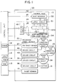
- Figure 1 shows electrical connections between a control unit and a recording unit according to an embodiment of the present invention.
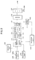
- Figure 2 is a block diagram schematically showing the construction of a facsimile apparatus according to an embodiment of the present invention.
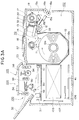
- Figure 3A is a side sectional view showing the mechanism portion of the facsimile apparatus according to the embodiment.
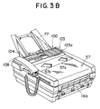
- Figure 3B is a pictorial perspective view of the facsimile apparatus.
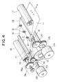
- Figure 4 shows the structure of conveying systems for an ink sheet and a recording sheet.
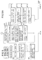
- Figure 5 is a flow chart showing the recording process of the embodiment.
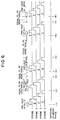
- Figure 6 shows the electrical energization timing for a thermal head in the recording process of the embodiment.
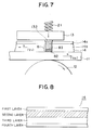
- Figure 7 shows the states of the recording sheet and the ink sheet during the recording in this embodiment.
- Figure 8 is a cross-sectional view of a multi-ink sheet used in this embodiment.
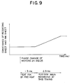
- Figure 9 shows the timing for the phase change of motors and the conveyance of the recording sheet and the ink sheet.
- Figure 10 is a flow-chart showing the recording process according to another embodiment of the present invention.
- a recording means may be caused to generate heat after the lapse of a predetermined time after the phases of motors for conveying a recording medium and an ink sheet, respectively, are changed.
- the phase change of said motors may thereby, for example, include the switching of coils of said motors so as to make a coil field rotate, causing a rotor of said motors to follow thereto correspondingly.
- Figures 1 to 4 show an embodiment of the present invention as it is applied to a facsimile apparatus.
- Figure 1 shows electrical connections between a control unit 101 and a recording unit 102 of the facsimile apparatus.
- Figure 2 is a block diagram schematically showing the construction of the facsimile apparatus,
- Figure 3A is a side sectional view of the facsimile apparatus,
- Figure 3B is a pictorial perspective view of the facsimile apparatus, and
- Figure 4 shows conveying mechanisms for a recording sheet and an ink sheet.
- the reference numeral 100 designates a reading unit for photoelectrically reading an original and outputting it as a digital image signal to a control unit 101.
- the reading unit 100 is provided with an original conveying motor, a CCD image sensor, etc.
- the construction of the control unit 101 will now be described.
- the reference numeral 110 denotes a line memory storing therein the image data of each line of image data. During the transmission or copying of the original, image data corresponding to one line from the reading unit 100 is stored in the line memory 110, and during the reception of image data, one line data of decoded received image data is stored in the line memory 110. The stored data is output to a recording unit 102, whereby image recording is effected.
- the reference numeral 111 designates an encoding/decoding unit for encoding transmitted image information by MH encoding or the like and decoding the received encoded image data and converting it into image data.
- the reference numeral 112 denotes a buffer memory for storing the transmitted or received encoded image data.
- These various portions of the control unit 101 are controlled, for example, by a CPU 113 such as a microprocessor.
- the control unit 101 is provided with not only the CPU 113, but comprises also a ROM 114 for storing the control program of the CPU 113 and various data, and a RAM 115 for temporarily preserving various data as e.g. the work area of the CPU 113.
- the recording 102 unit is provided with a thermal line head (provided with heat generating elements over the full recording width) for effecting image recording on a recording sheet by means of a heat transfer recording method.
- the construction of this recording unit 102 will be described later in detail with reference to Figure 3.
- the reference numeral 103 denotes an operation unit including a key for controlling various functions such as transmission starting, a telephone number input key, etc., and the reference character 103a designates a switch for indicating the kind of the ink sheet 14. When the switch 103a is ON, it indicates that a multiprint ink sheet is mounted, and when the switch 103a is OFF, it indicates that an ordinary ink sheet (a so-called one-time ink sheet) is mounted.
- the reference numeral 104 denotes an indicating unit usually provided adjacent to the operation unit 103 for indicating various functions and the state or the like of the apparatus.
- the reference numeral 105 designates a power source unit for supplying electric power to the entire apparatus.
- the reference numeral 106 denotes a modem (modemodulator), the reference numeral 107 designates a net control unit (NCU), and the reference numeral 108 denotes a telephone set.
- the reference numeral 10 designates a roll of paper comprising a recording sheet 11 which is plain paper wound into the shape of a roll on a core 10a.
- This roll of paper 10 is rotatably contained in the apparatus so that the recording sheet 11 can be supplied to the thermal head 13 by the rotation of a platen roller 12 in the direction of arrow.
- Denoted by 10b is a roll-of-paper loading portion which is removably loaded with the roll of paper 10.
- the platen roller 12 serves to convey the recording sheet 11 in the direction of arrow B and to press an ink sheet 14, and the recording sheet 11 between it and a heat generating member 132 of the thermal head 13.
- discharge rollers 16 (16a, 16b) By further rotation of the platen roller 12.
- the recording sheet 11 When image recording for one page is terminated, the recording sheet 11 is cut into page size by the meshing engagement of cutters 15 (15a, 15b) and is discharged.
- the reference numeral 17 denotes an ink sheet supply roll on which the ink sheet 14 is wound
- the reference numeral 18 designates an ink sheet take-up roll which is driven by an ink sheet conveying motor which will be described later to thereby take up the ink sheet 14 in the direction of arrow A.
- the ink sheet supply roll 17 and the ink sheet take-up roll 18 are removably mounted in an ink sheet loading portion 70 within the apparatus body.
- the reference numeral 19 designates a sensor for detecting the remaining quantity of the ink sheet 14 and for detecting the conveyance velocity of the ink sheet 14.
- the reference numeral 20 denotes an ink sheet sensor for detecting the presence or absence of the ink sheet 14.
- the reference numeral 21 designates a spring for urging the thermal head 13 against the platen roller 12 with the recording sheet 11 and the ink sheet 14 interposed therebetween.
- the reference numeral 22 denotes a recording sheet sensor for detecting the presence or absence of the recording sheet 11.
- the reference numeral 30 designates a light source for illuminating an original 32.
- the light reflected by the original 32 is input to a CCD sensor 31 through an optical system (mirrors 50, 51 and a lens 52) and converted into an electrical signal.
- the original 32 is conveyed corresponding to the reading speed available for the original 32 by conveying rollers 53, 54, 55 and 56 driven by an original conveying motor (not shown).
- the reference numeral 57 denotes an original supporting table. A plurality of originals 32 placed on the original supporting table 57 are separated one by one by the cooperation between the conveying roller 54 and a press-separating piece 58 while being guided by a slider 57a, and are conveyed to the reading unit 100.
- the reference numeral 41 designates a control base plate constituting the essential portion of the control unit 101. Various control signals are output to various portions of the apparatus by this control base plate 41.
- the reference numeral 106 denotes a modem base plate unit, and the reference numeral 107 designates an NCU base plate unit.
- FIG. 4 shows the details of conveying mechanisms for the ink sheet 14 and the recording sheet 11.
- the reference numeral 24 denotes a recording sheet conveying motor for rotatively driving the platen roller 12 to thereby convey the recording sheet 11 in the direction of arrow B opposite to the direction of arrow A.
- the reference numeral 25 designates an ink sheet conveying motor for conveying the ink sheet 14 in the direction of arrow A with the aid of a capstan roller 71 and a pinch roller 72.
- the reference numerals 26 and 27 denote transmission gears for transmitting the rotation of the recording sheet conveying motor 24 to the platen roller 12, and the reference numerals 73 and 74 designate transmission gears for transmitting the rotation of the ink sheet conveying motor 25 to the capstan roller 71.
- the reference numeral 75 denotes a slide clutch unit.
- the ratio between the gears 73 and 74 such that the length of the ink sheet 14 taken onto the take-up roll 18 by the rotation of a gear 75a may be greater than the length of the ink sheet 14 conveyed by the capstan roller 71, the ink sheet 14 conveyed by the capstan roller 71 is reliably taken onto the take-up roll 18.
- An amount corresponding to the difference between the amount of the ink sheet 14 taken up by the take-up roll 18 and the amount of the ink sheet 14 conveyed by the capstan roller 71 is absorbed by the slide clutch unit 75. Thereby, the fluctuation of the conveyance velocity (amount) of the ink sheet 14 by the fluctuation of the take-up diameter of the take-up roll 18 can be suppressed.
- the directions of conveyance A and B of the recording sheet 11 and the ink sheet 14 are made opposite to each other, whereby the direction in which images are successively recorded lengthwise of the recording sheet 11 (the direction of arrow A, i.e., the direction opposite to the direction of conveyance of the recording sheet 11) and the direction A of conveyance of the ink sheet 14 coincide with each other.
- Figure 1 shows electrical connections between the control unit 101 and the recording unit 102 in the facsimile apparatus, and in Figure 1, portions common to those in other figures are designated by identical reference numerals.
- the thermal head 13 is a line head as previously mentioned.
- This thermal head 13 is provided with a shift register 130 for receiving as inputs the serial recording data for one line and shift clock 43 from the control unit 101, a shift register for receiving pre-heat data as an input, a latch circuit for latching the data of the shift register 130 and the data of a shift register 134 for pre-heat data by a true latch signal 44 and a pre-latch signal 44a, respectively, and a heat generating element 132 comprising a plurality of heat generating resistance members corresponding to one line.
- the heat generating element 132 is divided into m blocks designated by 132-1 to 132-m and is driven.
- the reference numeral 133 denotes a temperature sensor attached to the thermal head 13 for detecting the temperature of the thermal head 13.
- the output signal 42 of this temperature sensor 133 is A/D-converted in the control unit 101 and input to the CPU 113.
- the CPU 113 detects the temperature of the thermal head 13, and changes the pulse width of a strobe signal 47 or changes the driving voltage of the thermal head 13 correspondingly to the detected temperature, thereby changing the applied energy to the thermal head 13 in conformity with the characteristic of the ink sheet 14.
- the reference numeral 116 designates a programmable timer of which the count time is set by the CPU 113 and which starts counting time when correspondingly instructed.
- the timer 116 operates so as to output an interruption signal, a time-out signal, etc. to the CPU 113 at each instructed time.
- the kind (characteristic) of the ink sheet 14 may be automatically discriminated by the switch 103a of the operation unit 103, or by means of a mark or the like printed on the ink sheet 14.
- the kind of the ink sheet 14 may be automatically discriminated by detecting a mask, a cut-away or a projection formed on the cartridge of the ink sheet.
- the reference numeral 46 denotes a driving circuit which receives as an input the driving signal for the thermal head 13 from the control unit 101 and which outputs a strobe signal 47 for driving the thermal head 13 at each block unit.
- This driving circuit 46 can change the voltage output to a power source line 45 for supplying an electric current to the heat generating element 132 of the thermal head 13, in accordance with the instructions from the control unit 101, thereby changing the applied energy to the thermal head 13.
- the reference numeral 36 designates a driving circuit for bringing the cutters 15 into meshing engagement with each other and for driving the same.
- the driving circuit 36 includes a cutter driving motor or the like.
- the reference numeral 39 denotes a sheet exhausting motor for rotatively driving the sheet discharge rollers 16.
- the reference numerals 35, 48 and 49 designate driver circuits for rotatively driving the corresponding sheet exhausting motor 39, the recording sheet conveying motor 24 and the ink sheet conveying motor 25.
- the sheet exhausting motor 39, the recording sheet conveying motor 24 and the ink sheet conveying motor 25 are stepping motors, whereas this is not restrictive, but they may be DC motors or the like.
- Figure 5 is a flow chart showing the recording process for one page in the facsimile apparatus.
- a program for executing this process is stored in the ROM 114 of the control unit 101.
- this process is started by image data for one line being stored in the line memory 110 and a state in which the recording operation can be started, and that it is discriminated in the control unit 101 by the switch 103a or the like that the multi-ink sheet 14 is mounted.
- the present embodiment is such that if within a predetermined time a after the termination of the current recording the transport of the data of the next line is terminated, pre-heating is not effected, but the phases of the motors 24 and 25 for conveying the recording sheet 11 and the ink sheet 14 are changed, whereafter the recording of the next line is started after the lapse of the time until the motors 24 and 25 start to move.
- the phases of the motors 24 and 25 for conveying the recording sheet 11 and the ink sheet 14 are changed, whereafter data ⁇ AAH and data ⁇ 55H are alternately used as pre-heat data, whereby pre-heating is effected.
- the program waits for the time from termination of the pre-heating until the motors start to move (in the present embodiment, the waiting time is zero), and then proceeds to the recording of the next line.
- the phases of the motors 24 and 25 for conveying the recording sheet 11 and the ink sheet 14 are changed, whereafter pre-heating is effected with all "1" (all black, i.e., all heat generating elements are caused to heat) as pre-heat data (in this case, energy smaller than energy for the main recording is applied to the thermal head 13 so that recording may not take place).
- pre-heating is effected with all "1" (all black, i.e., all heat generating elements are caused to heat) as pre-heat data (in this case, energy smaller than energy for the main recording is applied to the thermal head 13 so that recording may not take place).
- the program waits for the time from the termination of this pre-heating until the motors start to move (in the present embodiment, the waiting time is zero), and then proceeds to the recording of the next line.
- the pre-heat data are changed depending on the time from the termination of the main recording until the termination of the transport of the data of the next line. That is, when the time until the termination of the transport of the data of the next line is long, the black rate of the pre-heat data is enhanced.
- the pre-heat width is fixed.
- pre-heating when the time until the termination of the transport of the data of the next line is less than a predetermined time, pre-heating is not effected, and when said time is equal to or greater than a, and less than b, pre-heat data of black rate 50% is used, and when said time is equal to or greater than b, pre-heat data of black rate 100% is used.
- the energy applied to each dot by pre-heating in the case of black rate 50% is made equal with data ⁇ AAH and ⁇ 55H being repetitively used. That is, the pre-heat data rotates cyclically and the energy applied to each dot of the head by pre-heating is under the same control.
- the black rate has been considered to be 0%, 50% and 100%, but finer control may be adopted.
- Figure 6 shows the phase change of the motors and various strobe waveforms.
- timing (1) the phase switching of the motors for the recording sheet and the ink sheet is effected.
- pre-heat with all "1" data is effected.
- timing (2) the current recording is effected.
- the transport of the data of the next line is terminated (the time from the termination of the main recording until the termination of the transport of the data of the next line is equal to or less than the predetermined time a) and therefore, the current recording is effected without pre-heating.
- timing (3) In a time less than b and equal to or more than the predetermined time a after the main recording has been terminated (timing (3)), the transport of the data of the next line is terminated (timing (4)) and therefore, here pre-heating is effected by data ⁇ 55H before the main recording is effected.
- timing (5) In a time equal to or more than the predetermined time b after the main recording has been terminated (timing (5)), the transport of the data of the next line is terminated (timing (6)) and therefore, here pre-heating is effected by data of all "1" (all black) before the main recording of the next line is effected.
- timing (7) In a time less than b and equal to or more than the predetermined time a after the main recording has been terminated (timing (7)), the transport of the data of the next line is terminated (timing (8)) and therefore, here pre-heating is effected by data ⁇ AAH.
- the preheat data may be all "1", i.e., all black.
- FIG 10 An example of such control is shown in Figure 10 (in which, as compared with the flow chart of Figure 5 to be described, steps S0, S15, S16 and S17-1 are eliminated).
- steps S0, S15, S16 and S17-1 are eliminated.
- an increase in the energy at the isolation point is necessary, because the information of the line preceding the isolation point is white and therefore it is not effective even if the preceding line is recorded as the pre-heat data. From these two points of view, it may be preferable to electrically energize and pre-heat all black information immediately before the current recording.
- the electrical energization of all black information is for keeping temperature, and the energy used therefor is non-recording energy. Also, during pre-heating, the recording sheet 11 and the ink sheet 14 are stationary and it is difficult for the ink to be transferred to the recording sheet 11.
- the main recording is effected at timing whereat the motors 24 and 25 for conveying the recording sheet 11 and the ink sheet 14, respectively, actually start to move after the phases of these motors are switched. So, according to the recording system of the present embodiment, melted (or sublimated depending on the kind of the ink) ink rubs against the recording sheet 11 and is thereby transferred to the recording sheet 11 and therefore, the ink can be transferred more efficiently by effecting move-writing (recording). If there is a predetermined or greater recording interval (e.g. 10 ms or more) after the switching of the motor phase has been effected, the thermal head 13 is caused to generate heat to thereby effect pre-heating, and in the meantime, the ink is heated and warmed.
- a predetermined or greater recording interval e.g. 10 ms or more
- Figure 9 shows the phase switching of the motors 24 and 25, the conveyance of the recording sheet 11 and the ink sheet 14, and the timing of the main recording.
- pre-heating is effected for 1.5 ms by the thermal head 13, where-after the main recording for 2.5 ms is performed.
- the recording data for one line is serially output to the shift register 130.
- all "1" data are transported to the shift register 130 for pre-heating.
- a pre-latch signal 44a is output and pre-heat data 134 for one line is stored in the latch circuit 131.
- the ink sheet conveying motor 25 is driven to convey the ink sheet 14 by 1/n lines.
- the recording sheet 11 is conveyed by one line.
- the length of this one line is set to about 1/15.4 mm, and the amounts of conveyance of the recording sheet 11 and the ink sheet 14 can be set by changing the energization pulse numbers of the recording sheet conveying motor 24 and the ink sheet conveying motor 25, respectively.
- the blocks of the heat generating resistance member 132 are electrically energized. It is to be understood that the energization time of each block is e.g. 0.2 ms.
- the process advances to a step S4, where a true latch signal 44 is output and the recording data for one line are stored in the latch circuit 131.
- step S5 one block of the heat generating resistance member 132 is electrically energized to thereby effect the recording of an image, and at a step S6, it is examined whether the electrical energization of all blocks of the thermal head 13 has been terminated. If at the step S6, the electrical energization of all blocks of the thermal head 13 is not terminated, the process advances to a step S7, where it is examined whether the recording data for the next line have been prepared. If the recording data for the next line is not prepared, the process advances to a step S8, where the recording data for the next line are successively transported to the shift register 130 of the thermal head 13.
- Whether the energization time of one block has passed during the data transport to the thermal head 13 is examined at a step S9. If the energization time (about 600 ⁇ s) has not passed, the process returns to the step S7, but if the energization time has passed, the process returns to the step S5, where the electrical energization of the next block is executed.
- the thermal head 13 is divided into four blocks and electrically energized, and the time required for the recording of one line is approximately 2.5 ms (600 ⁇ s x 4 blocks).
- step S10 the timer 116 starts to count time.
- step S11 it is examined whether the image recording for one page has been terminated. If the image recording for one page is not terminated, the process advances to a step S12, where it is examined whether all the image data of the next line have been transported to the shift register 130 of the thermal head 13. If said image data have not been transported, at a step S13, the data transporting process for transporting the data of the next line to the thermal head 13 is executed if such data is prepared.
- step S12 the image data of one line to be next recorded is transported to the thermal head 13
- the process advances to a step S14, where the timer 16 examines whether the predetermined time a has passed. If the predetermined time a has not passed, the process advances to a step S17-2, where the ink sheet conveying motor 25 is driven to convey the ink sheet 14 by 1/n lines. Then, at a step S17-3, the recording sheet 11 is conveyed by one line.
- step S17-4 the program waits until the motors 24 and 25 start to move, and at a step S17-5, the true latch signal 44 is output and recording data for one line is stored in the latch circuit 131.
- step S15 when the predetermined time a has passed, the process advances to a step S15, where it is judged whether the predetermined time b has passed. If the predetermined time b has passed, the process advances to the step S2, and if the predetermined time b has not passed, PRI-DATA is rotated by one bit (a step S16) and one line of the pattern of PRI-DATA is output as pre-heat data 134 (a step S17-1).
- step S11 image recording for one page is terminated
- the process advances to a step S18, where the recording sheet 11 is conveyed toward the paper discharge rollers 16a and 16b by a predetermined amount.
- the cutters 15a and 15b are driven into meshing engagement with each other, whereby the recording sheet 11 is cut into page size.
- step S20 the recording sheet conveying motor 24 is driven reversely to return the recording sheet 11 by a distance corresponding to the spacing between the thermal head 13 and the cutters 15, and the cutting process for the recording sheet 11 is terminated.
- the thermal head 13 is caused to generate heat after the lapse of a predetermined time after the phases of the ink sheet conveying motor 25 and the recording sheet conveying motor 24 are changed and therefore, the efficiency of the transfer of the ink to the recording sheet 11 is improved.
- Figure 7 shows the image recording condition when a recording of images is performed with the directions of conveyance of the recording sheet 11 and the ink sheet 14 made opposite to each other.
- the recording sheet 11 and the ink sheet 14 are nipped between the platen roller 12 and the thermal head 13, and the thermal head 13 is urged against the platen roller 12 with a predetermined pressure by a spring 21.
- the recording sheet 11 is conveyed at a velocity V P in the direction of arrow B by the rotation of the platen roller 12.
- the ink sheet 14 is conveyed at a velocity V I in the direction of arrow A by the ink sheet conveying motor 25.
- the heat generating resistance member 132 of the thermal head 13 is electrically energized by the power source 105 and heated, the portion of the ink sheet 14 which is indicated by hatching 81 is heated.
- the reference character 14a designates the base film of the ink sheet 14
- the reference character 14b denotes the ink layer of the ink sheet 14.
- the ink of the ink layer 81 heated by the heat generating resistance member 132 is melted, and that portion thereof which is indicated by 82 is transferred to the recording sheet 11.
- This transferred ink layer portion 82 corresponds to approximately 1/n of the ink layer designated by 81.
- the heating time for the thermal head 13 is as short as about 0.6 ms and therefore, by making the directions of conveyance A and B of the ink sheet 14 and the recording sheet 11 opposite to each other, the relative velocity V PI of the ink sheet 14 and the recording sheet 11 is increased.
- Figure 8 is a cross-sectional view of the ink sheet 14 used in the multiprinting of the present embodiment, and as shown there, the ink sheet 14 is comprised of four layers.
- a second layer represents a base film which provides a support for the ink sheet 14.
- the base film may advantageously be an aromatic polyamide film of high heat resisting property or a condenser paper, but conventional polyester film will also stand the use.
- the thickness of this film may advantageously be as small as possible in respect of the quality of printing from its role as a medium, and may desirably be 3 - 8 ⁇ m from the viewpoint of strength.
- a third layer represents an ink layer containing an amount of ink transferable n times to the recording sheet 11.
- the main components of this layer are a resin such as EVA as an adhesive agent, carbon black or nigrosine dye for coloring, and carnauba wax or paraffin wax as a binding material, and these components are arranged so as to stand n times of use in the sample portion.
- the amount of application of these materials may desirably be 4 - 8 g/m 2 , but can be chosen as desired because sensitivity and density differ depending on the amount of application.
- a fourth layer represents a top coating layer which is not concerned in printing and which is arranged for preventing the ink of the third layer from being pressure-transferred to the recording sheet 11, and is formed of transparent wax or the like. Thus, it is only the transparent fourth layer that is pressure-transferred, and the ground stain of the recording sheet 11 can be prevented.
- a first layer represents a heat resisting coat layer for protecting the second layer, i.e., the base film, from the heat of the thermal head 13.
- This is suitable for multiprinting in which heat energy for n lines may be applied to the same portion (when black information is continuous), but whether it should be used or not can be suitably chosen. It is also effective for a base film of relatively low heat resisting property such as polyester film.
- the construction of the ink sheet 14 is not limited to this embodiment, but use may also be made of an ink sheet 14 comprising, for example, a base layer and a porous ink retaining layer provided on one side of the base layer and containing the ink, or of an ink sheet 14 comprising a base film and a heat resisting ink layer provided on the base film and having a fine porous net-like structure, the ink layer containing the ink.
- the material of the base film may be formed as a film of, for example, polyamide, polyethylene, polyester, polyvinyl chloride, triacetyl cellulose, nylon or the like, or paper.
- the heat resisting coat layer is not always necessary, but the material thereof may be, for example, silicone resin, epoxy resin, fluorine resin, etholocellulose or the like.
- an ink sheet 14 comprising a base member formed of polyethylene terephthalate, polyethylene naphthalate, aromatic polyamide film or the like, and a color material layer provided on the base member and formed of guanamine resin and fluorine resin and containing spacer particles and dyestuff.
- the heating system in the heat transfer printer is not limited to the aforedescribed thermal head system using a thermal head 13, but may be, for example, an electrical energization system or a laser transfer system.
- the present embodiment has been described as an example using a thermal line head, whereas this is not restrictive, but the present invention may be a so-called serial type heat transfer printer. Also, the present embodiment has been described with respect to the case of multiprinting, whereas this is not restrictive, but of course, the present invention can also be applied to the ordinary heat transfer recording using a one-time ink sheet.
- this embodiment has been shown as being provided with an ink sheet conveying motor 25 and a recording sheet conveying motor 24, whereas the present invention is not restricted thereto, but design may be made such that the ink sheet 14 and the recording sheet 11 are conveyed by the drive force of a single motor.
- the recording medium 11 is not limited to recording paper, but may be, for example, cloth, a plastic sheet or the like if they permit the transfer of ink thereto.
- the ink sheet 14 is not limited to the roll construction shown in the embodiment, but may be, for example, of the so-called ink sheet cassette type in which an ink sheet is contained in a housing body removably mounted in the body of a recording apparatus.
- this embodiment is effective in a recording apparatus such as a facsimile apparatus in which the time interval between image data for one line may become non-uniform and lengthy.
- a heat transfer recording apparatus and a facsimile apparatus which can record images of high quality.
Landscapes
- Electronic Switches (AREA)
- Impression-Transfer Materials And Handling Thereof (AREA)
- Fax Reproducing Arrangements (AREA)
Claims (17)
- Wärmeübertragungsaufzeichnungsgerät zum Übertragen einer Tinte einer Tintenunterlage auf ein Aufzeichnungsmedium, um dadurch das Aufzeichnen eines Bilds auf dem Aufzeichnungsmedium zu bewirken, mit:- einem ersten Motor zum Transportieren einer Tintenunterlage,- einem zweiten Motor zum Transportieren eines Aufzeichnungsmediums,- einer Aufzeichnungseinheit, welche eine Aufzeichnungseinrichtung zum Einwirken auf die Tintenunterlage aufweist, um das Aufzeichnen des Bilds auf dem Aufzeichnungsmedium zu bewirken, und- einer Steuereinrichtung zum Steuern der Aufzeichnungseinheit,dadurch gekennzeichnet, daß die Steuereinrichtung (101) die Aufzeichnungseinheit (102) so steuert, daß die Aufzeichnungseinheit (102) die Aufzeichnungseinrichtung (13) veranlaßt, nicht aufzuzeichnen, bis der erste und der zweite Motor anlaufen, nachdem deren Phasen geändert sind, und die Aufzeichnungseinrichtung (13) veranlaßt, in Übereinstimmung mit einer Zeitsteuerung aufzuzeichnen, unter welcher die Motoren sich zu bewegen beginnen, wobei das Aufzeichnen durch das Übertragen einer erhitzten Tintenmenge aus der Tintenunterlage (14) auf das Aufzeichnungsmedium (11) bewirkt wird, während sich die Tintenunterlage (14) und das Aufzeichnungsmedium (11) aneinander reiben und eine Relativgeschwindigkeit in einem Übertragungsabschnitt der Tinte aufweisen.
- Wärmeübertragungsaufzeichnungsgerät gemäß Anspruch 1,
dadurch gekennzeichnet, daß das Wärmeübertragungsaufzeichnungsgerät ferner eine
Vorheizeinrichtung aufweist, um die Aufzeichnungseinheit (102) zu veranlassen, Wärme zu erzeugen, um dadurch das Vorheizen zwischen dem Beenden des Aufzeichnens einer Zeile und dem Beenden des Datentransports für eine nächste Zeile zu bewirken. - Wärmeübertragungsaufzeichnungsgerät gemäß Anspruch 2,
dadurch gekennzeichnet, daß das Vorheizen mit allen Schwarzdaten bewirkt wird. - Wärmeübertragungsaufzeichnungsgerät gemäß Anspruch 2 oder 3,
dadurch gekennzeichnet, daß die Aufzeichnungseinrichtung (13), wenn notwendig, nach dem Ändern der Phase und vor dem Aufzeichnen vorgeheizt wird. - Wärmeübertragungsaufzeichnungsgerät gemäß Anspruch 1,
dadurch gekennzeichnet, daß die Transportrichtung der Tintenunterlage (14) der Transportrichtung des Aufzeichnungsmediums (11) entgegengesetzt ist. - Wärmeübertragungsaufzeichnungsgerät gemäß Anspruch 5,
dadurch gekennzeichnet, daß die Transportlänge der Tintenunterlage (14) zum Aufzeichnen kürzer als die Transportlänge des Aufzeichnungsmediums (11) ist. - Wärmeübertragungsaufzeichnungsgerät gemäß Anspruch 1,
dadurch gekennzeichnet, daß das Aufzeichnungsmedium während des Heizens der Aufzeichnungseinheit (102) zum Aufzeichnen bewegt wird. - Wärmeübertragungsaufzeichnungsgerät gemäß Anspruch 1,
dadurch gekennzeichnet, daß die Aufzeichnungseinrichtung (13) ein Thermokopf (13) ist. - Wärmeübertragungsaufzeichnungsgerät gemäß Anspruch 1,
dadurch gekennzeichnet, daß das Wärmeübertragungsaufzeichnungsgerät ferner eine Sende-/Empfangseinrichtung (111, 112) zum Senden und Empfangen von Bildsignalen aufweist. - Wärmeübertragungsaufzeichnungsgerät gemäß Anspruch 1,
dadurch gekennzeichnet, daß das Wärmeübertragungsaufzeichnungsgerät ferner eine Bildsignal-Eingabeeinrichtung (31, 50, 51, 52, 110) zum Eingeben eines Bildsignals aufweist. - Wärmeübertragungsaufzeichnungsgerät gemäß Anspruch 1,
dadurch gekennzeichnet, daß das Wärmeübertragungsaufzeichnungsgerät ferner eine Leseeinrichtung (100) zum Lesen des Bilds eines Originals aufweist. - Wärmeübertragungsaufzeichnungsgerät gemäß Anspruch 11,
dadurch gekennzeichnet, daß das Wärmeübertragungsaufzeichnungsgerät ferner eine Sende-/Empfangseinrichtung (111, 112) zum Senden und Empfangen von Bildsignalen aufweist. - Wärmeübertragungsaufzeichnungsverfahren zum Übertragen einer Tinte einer Tintenunterlage auf ein Aufzeichnungsmedium, um dadurch das Aufzeichnen eines Bilds auf dem Aufzeichnungsmedium zu bewirken, wobei die Tintenunterlage durch einen ersten Motor transportiert wird und das Aufzeichnungsmedium durch einen zweiten Motor transportiert wird, und wobei das Aufzeichnen auf dem Aufzeichnungsmedium durch das Einwirken einer Aufzeichnungseinheit mit einer Aufzeichnungseinrichtung auf die Tintenunterlage bewirkt wird,
dadurch gekennzeichnet, daß die Aufzeichnungseinheit (102) so gesteuert wird, daß die Aufzeichnungseinrichtung (13) veranlaßt wird, nicht aufzuzeichnen, bis der erste und der zweite Motor nach dem Ändern deren Phasen anlaufen, und die Aufzeichnungseinrichtung (13) veranlaßt wird, in Übereinstimmung mit einer Zeitsteuerung, unter welcher der erste und der zweite Motor sich zu drehen beginnen, aufzuzeichnen, wobei das Aufzeichnen durch Übertragen einer erhitzten Tintenmenge von der Tintenunterlage (14) auf das Aufzeichnungsmedium (11) bewirkt wird, während die Tintenunterlage (14) und das Aufzeichnungsmedium (11) aneinander gerieben werden und eine Relativgeschwindigkeit in einem Übertragungsabschnitt der Tinte aufweisen. - Wärmeübertragungsaufzeichnungsverfahren gemäß Anspruch 13,
dadurch gekennzeichnet, daß das Wärmeübertragungsaufzeichnungsverfahren ferner den Schritt des Ausführens des Vorheizens aufweist, wenn eine Aufzeichnungspause länger als die vorbestimmte Zeitdauer vor der durch die Aufzeichnungseinheit (102) bewirkten Aufzeichnungsoperation ist. - Wärmeübertragungsaufzeichnungsverfahren gemäß Anspruch 14,
dadurch gekennzeichnet, daß eine Bedingung des Vorheizens als Reaktion auf eine Länge der Aufzeichnungspause geändert wird. - Wärmeübertragungsaufzeichnungsverfahren gemäß Anspruch 13,
dadurch gekennzeichnet, daß die Transportrichtung der Tintenunterlage (14) der Transportrichtung des Aufzeichnungsmediums (11) entgegengesetzt ist. - Wärmeübertragungsaufzeichnungsverfahren gemäß Anspruch 13,
dadurch gekennzeichnet, daß die Transportlänge der Tintenunterlage (14) zum Aufzeichnen kürzer als die Transportlänge des Aufzeichnungsmediums (11) ist.
Applications Claiming Priority (2)
| Application Number | Priority Date | Filing Date | Title |
|---|---|---|---|
| JP1198270A JPH0361559A (ja) | 1989-07-31 | 1989-07-31 | 熱転写記録装置及び該装置を用いたファクシミリ装置 |
| JP198270/89 | 1989-07-31 |
Publications (3)
| Publication Number | Publication Date |
|---|---|
| EP0411540A2 EP0411540A2 (de) | 1991-02-06 |
| EP0411540A3 EP0411540A3 (en) | 1992-04-08 |
| EP0411540B1 true EP0411540B1 (de) | 1997-02-26 |
Family
ID=16388344
Family Applications (1)
| Application Number | Title | Priority Date | Filing Date |
|---|---|---|---|
| EP19900114599 Expired - Lifetime EP0411540B1 (de) | 1989-07-31 | 1990-07-30 | Wärmeübertragungsaufzeichnungsgerät und Faksimilevorrichtung |
Country Status (3)
| Country | Link |
|---|---|
| EP (1) | EP0411540B1 (de) |
| JP (1) | JPH0361559A (de) |
| DE (1) | DE69029981T2 (de) |
Families Citing this family (3)
| Publication number | Priority date | Publication date | Assignee | Title |
|---|---|---|---|---|
| EP0500008B1 (de) * | 1991-02-18 | 1998-12-23 | Canon Kabushiki Kaisha | Aufzeichnungsgerät und Faksimilegerät, in dem dieses Aufzeichnungsgerät angewendet wird |
| EP0504878B1 (de) * | 1991-03-20 | 1997-06-04 | Canon Kabushiki Kaisha | Bildaufzeichnungsvorrichtung |
| DE4225798A1 (de) * | 1992-07-31 | 1994-02-03 | Francotyp Postalia Gmbh | Sparsames Thermotransferdruckverfahren und Anordnung zur Durchführung |
Family Cites Families (2)
| Publication number | Priority date | Publication date | Assignee | Title |
|---|---|---|---|---|
| JPS6290080A (ja) * | 1985-10-16 | 1987-04-24 | Hitachi Ltd | 感熱記録装置 |
| JPS63317362A (ja) * | 1987-06-19 | 1988-12-26 | Shinko Electric Co Ltd | サ−マルプリンタの印刷方法 |
-
1989
- 1989-07-31 JP JP1198270A patent/JPH0361559A/ja active Pending
-
1990
- 1990-07-30 DE DE1990629981 patent/DE69029981T2/de not_active Expired - Fee Related
- 1990-07-30 EP EP19900114599 patent/EP0411540B1/de not_active Expired - Lifetime
Also Published As
| Publication number | Publication date |
|---|---|
| DE69029981D1 (de) | 1997-04-03 |
| EP0411540A3 (en) | 1992-04-08 |
| DE69029981T2 (de) | 1997-07-03 |
| JPH0361559A (ja) | 1991-03-18 |
| EP0411540A2 (de) | 1991-02-06 |
Similar Documents
| Publication | Publication Date | Title |
|---|---|---|
| EP0360282B1 (de) | Verfahren und Vorrichtung zum Aufzeichnen durch Thermoübertragung | |
| EP0360281B1 (de) | Verfahren und Vorrichtung zum Aufzeichnen durch Thermoübertragung | |
| EP0367286B1 (de) | Aufzeichnungsvorrichtung mit Wärmeübertragung und Faksimilegerät | |
| JPH0349964A (ja) | 熱転写記録装置及び方法 | |
| US5231421A (en) | Thermal transfer recording apparatus with delayed driving | |
| EP0411540A2 (de) | Wärmeübertragungsaufzeichnungsgerät und Faksimilevorrichtung | |
| EP0409243B1 (de) | Apparat und Verfahren zum Aufzeichnen | |
| US5144329A (en) | Recording apparatus and method which takes into account image information being recorded | |
| US5623299A (en) | Thermal transfer recording apparatus with ink sheet and recording medium transported by predetermined amounts | |
| EP0368325A2 (de) | Aufzeichnungsvorrichtung mit Wärmeübertragung und Faksimilegerät | |
| EP0368324B1 (de) | Thermotransfer-Aufzeichnungsvorrichtung und Methode | |
| JPH02121866A (ja) | 熱転写記録装置及び該装置を用いたフアクシミリ装置 | |
| US5248996A (en) | Thermal transfer recording apparatus which avoids ink sheet sticking after recording data reception is interrupted | |
| US5410336A (en) | Recording method and apparatus for controlling ink sheet conveyance in accordance with an interval between recording operations | |
| EP0368323B1 (de) | Aufzeichnungsvorrichtung mit Wärmeübertragung und Faksimilegerät | |
| JPH0298473A (ja) | 熱転写記録装置及び該装置を用いたフアクシミリ装置 | |
| EP0363962B1 (de) | Aufzeichnungsvorrichtung und -Verfahren mit Wärmeübertragung | |
| JP2578953B2 (ja) | 熱転写記録装置及び該装置を用いたフアクシミリ装置 | |
| JPH04223177A (ja) | 熱転写記録装置及び該装置を用いたファクシミリ装置 | |
| JPH06183050A (ja) | 熱転写記録装置及び該装置を用いたファクシミリ装置 | |
| JPH02128856A (ja) | 熱転写記録装置及び該装置を用いたフアクシミリ装置 | |
| JPH0584939A (ja) | 熱転写記録装置及び該装置を用いたフアクシミリ装置 | |
| JPH06191071A (ja) | 熱転写記録装置及び該装置を用いたファクシミリ装置 | |
| JPH0342261A (ja) | 熱転写記録装置 | |
| JPH05292272A (ja) | 熱転写記録装置及び該装置を用いたファクシミリ装置 |
Legal Events
| Date | Code | Title | Description |
|---|---|---|---|
| PUAI | Public reference made under article 153(3) epc to a published international application that has entered the european phase |
Free format text: ORIGINAL CODE: 0009012 |
|
| AK | Designated contracting states |
Kind code of ref document: A2 Designated state(s): DE FR GB IT NL |
|
| 17P | Request for examination filed |
Effective date: 19901221 |
|
| PUAL | Search report despatched |
Free format text: ORIGINAL CODE: 0009013 |
|
| AK | Designated contracting states |
Kind code of ref document: A3 Designated state(s): DE FR GB IT NL |
|
| 17Q | First examination report despatched |
Effective date: 19921113 |
|
| GRAG | Despatch of communication of intention to grant |
Free format text: ORIGINAL CODE: EPIDOS AGRA |
|
| GRAH | Despatch of communication of intention to grant a patent |
Free format text: ORIGINAL CODE: EPIDOS IGRA |
|
| GRAH | Despatch of communication of intention to grant a patent |
Free format text: ORIGINAL CODE: EPIDOS IGRA |
|
| GRAA | (expected) grant |
Free format text: ORIGINAL CODE: 0009210 |
|
| AK | Designated contracting states |
Kind code of ref document: B1 Designated state(s): DE FR GB IT NL |
|
| PG25 | Lapsed in a contracting state [announced via postgrant information from national office to epo] |
Ref country code: IT Free format text: LAPSE BECAUSE OF FAILURE TO SUBMIT A TRANSLATION OF THE DESCRIPTION OR TO PAY THE FEE WITHIN THE PRE;WARNING: LAPSES OF ITALIAN PATENTS WITH EFFECTIVE DATE BEFORE 2007 MAY HAVE OCCURRED AT ANY TIME BEFORE 2007. THE CORRECT EFFECTIVE DATE MAY BE DIFFERENT FROM THE ONE RECORDED.SCRIBED TIME-LIMIT Effective date: 19970226 Ref country code: NL Free format text: LAPSE BECAUSE OF FAILURE TO SUBMIT A TRANSLATION OF THE DESCRIPTION OR TO PAY THE FEE WITHIN THE PRESCRIBED TIME-LIMIT Effective date: 19970226 |
|
| REF | Corresponds to: |
Ref document number: 69029981 Country of ref document: DE Date of ref document: 19970403 |
|
| ET | Fr: translation filed | ||
| NLV1 | Nl: lapsed or annulled due to failure to fulfill the requirements of art. 29p and 29m of the patents act | ||
| PLBE | No opposition filed within time limit |
Free format text: ORIGINAL CODE: 0009261 |
|
| STAA | Information on the status of an ep patent application or granted ep patent |
Free format text: STATUS: NO OPPOSITION FILED WITHIN TIME LIMIT |
|
| 26N | No opposition filed | ||
| REG | Reference to a national code |
Ref country code: GB Ref legal event code: IF02 |
|
| PGFP | Annual fee paid to national office [announced via postgrant information from national office to epo] |
Ref country code: DE Payment date: 20070726 Year of fee payment: 18 |
|
| PGFP | Annual fee paid to national office [announced via postgrant information from national office to epo] |
Ref country code: GB Payment date: 20070725 Year of fee payment: 18 |
|
| PGFP | Annual fee paid to national office [announced via postgrant information from national office to epo] |
Ref country code: FR Payment date: 20070710 Year of fee payment: 18 |
|
| GBPC | Gb: european patent ceased through non-payment of renewal fee |
Effective date: 20080730 |
|
| PG25 | Lapsed in a contracting state [announced via postgrant information from national office to epo] |
Ref country code: DE Free format text: LAPSE BECAUSE OF NON-PAYMENT OF DUE FEES Effective date: 20090203 |
|
| REG | Reference to a national code |
Ref country code: FR Ref legal event code: ST Effective date: 20090331 |
|
| PG25 | Lapsed in a contracting state [announced via postgrant information from national office to epo] |
Ref country code: GB Free format text: LAPSE BECAUSE OF NON-PAYMENT OF DUE FEES Effective date: 20080730 |
|
| PG25 | Lapsed in a contracting state [announced via postgrant information from national office to epo] |
Ref country code: FR Free format text: LAPSE BECAUSE OF NON-PAYMENT OF DUE FEES Effective date: 20080731 |