EP0411930A2 - Schwimmbad oder Wirbelbeckensystem und Rückschlagventil dafür - Google Patents
Schwimmbad oder Wirbelbeckensystem und Rückschlagventil dafür Download PDFInfo
- Publication number
- EP0411930A2 EP0411930A2 EP90308481A EP90308481A EP0411930A2 EP 0411930 A2 EP0411930 A2 EP 0411930A2 EP 90308481 A EP90308481 A EP 90308481A EP 90308481 A EP90308481 A EP 90308481A EP 0411930 A2 EP0411930 A2 EP 0411930A2
- Authority
- EP
- European Patent Office
- Prior art keywords
- closure element
- valve
- operating member
- passage
- seating
- Prior art date
- Legal status (The legal status is an assumption and is not a legal conclusion. Google has not performed a legal analysis and makes no representation as to the accuracy of the status listed.)
- Withdrawn
Links
Images
Classifications
-
- F—MECHANICAL ENGINEERING; LIGHTING; HEATING; WEAPONS; BLASTING
- F16—ENGINEERING ELEMENTS AND UNITS; GENERAL MEASURES FOR PRODUCING AND MAINTAINING EFFECTIVE FUNCTIONING OF MACHINES OR INSTALLATIONS; THERMAL INSULATION IN GENERAL
- F16K—VALVES; TAPS; COCKS; ACTUATING-FLOATS; DEVICES FOR VENTING OR AERATING
- F16K15/00—Check valves
- F16K15/02—Check valves with guided rigid valve members
-
- A—HUMAN NECESSITIES
- A61—MEDICAL OR VETERINARY SCIENCE; HYGIENE
- A61H—PHYSICAL THERAPY APPARATUS, e.g. DEVICES FOR LOCATING OR STIMULATING REFLEX POINTS IN THE BODY; ARTIFICIAL RESPIRATION; MASSAGE; BATHING DEVICES FOR SPECIAL THERAPEUTIC OR HYGIENIC PURPOSES OR SPECIFIC PARTS OF THE BODY
- A61H33/00—Bathing devices for special therapeutic or hygienic purposes
- A61H33/60—Components specifically designed for the therapeutic baths of groups A61H33/00
-
- A—HUMAN NECESSITIES
- A61—MEDICAL OR VETERINARY SCIENCE; HYGIENE
- A61H—PHYSICAL THERAPY APPARATUS, e.g. DEVICES FOR LOCATING OR STIMULATING REFLEX POINTS IN THE BODY; ARTIFICIAL RESPIRATION; MASSAGE; BATHING DEVICES FOR SPECIAL THERAPEUTIC OR HYGIENIC PURPOSES OR SPECIFIC PARTS OF THE BODY
- A61H33/00—Bathing devices for special therapeutic or hygienic purposes
- A61H33/02—Bathing devices for use with gas-containing liquid, or liquid in which gas is led or generated, e.g. carbon dioxide baths
- A61H2033/023—Bathing devices for use with gas-containing liquid, or liquid in which gas is led or generated, e.g. carbon dioxide baths with means in the air supply lines to prevent back-feed of water, e.g. anti-backflow valves, draining devices
Definitions
- This invention relates to an air spa or whirlpool bath system arranged for an air and/or water stream to be injected into the bath through a valve of the kind referred to hereinafter as a non-return valve of the kind defined.
- a movable closure element is arranged to abut a seating, in a closed condition of the valve, to close an outlet from a fluid supply passage.
- a predetermined fluid pressure in the passage on the upstream side of the closure element that is, over and above an assumed pressure on the downstream side
- the element becomes displaced from the seating to open the passage outlet and permit a forwards flow through the open valve.
- the closure element Upon the pressure on the upstream side falling away the closure element becomes returned to the seating, so to close the valve and prevent any return flow through the passage.
- the element may be arranged to return to the seating by virtue of its weight alone, or return may be assisted or caused by suitable biasing means, for example comprising a return spring.
- suitable biasing means for example comprising a return spring.
- closure element in such a non-return valve is arranged to be displaced from the seating by the developed upstream pressure acting directly on the closure element itself.
- the force with which the closure element can be arranged to abut the seating i.e. the sealing force
- the available upstream pressure which must act to open the valve is limited by the available upstream pressure which must act to open the valve.
- Non-return valves of the kind defined are used, for example, in so-called air spa and whirlpool bath systems, in which air and/or water streams are injected into baths for specific therapeutic purposes or, more generally, for the pleasant and relaxing effects experienced by the bather.
- air spa and whirlpool bath systems in which air and/or water streams are injected into baths for specific therapeutic purposes or, more generally, for the pleasant and relaxing effects experienced by the bather.
- warm air from a blower can be discharged through a plurality of such non-return valves into the bath, the valves being opened as a consequence of upstream pressure developed in the supply passage by the blower, and the valves closing when the blower is switched off, to prevent water from the bath passing as a return flow through the passage towards the blower.
- the invention is characterised in that the closure element is provided by a closure mechanism which comprises biasing means arranged to urge the closure element against the seating in the closed condition of the valve, the biasing means comprising a displaceable operating member which is subject to the pressure within the fluid supply passage for displacement outwardly of the passage caused by an increase in pressure within the passage, the effective area of the operating member exposed to the passage being greater than the effective area of the closure element exposed to the passage in the closed condition of the valve and displacement of the operating member causing or permitting displacement of the closure element from the seating to open the valve.
- the displaceable operating member of the biasing means may conveniently comprise a movable element in the general form of a flexible diaphragm, which is exposed to pressure from the supply passage on one side and atmospheric pressure (ordinarily) on the other.
- the diaphragm or other operating member may be resiliently supported, or may itself be resilient, in order to bias it against displacement.
- the operating member might be fixed to the closure element so that displacement of the operating member is the direct cause of displacement of the closure element from the valve seating to open the valve.
- the operating member is arranged to be coupled to the closure element in the closed condition of the valve but to become released from the closure element for displacement of the latter (under pressure from the supply passage) independently of the operating member to open the valve.
- the operating member and the closure element are magnetically coupled together in the closed condition of the valve, enabling the operating member to urge the closure element firmly against the seating.
- the movable operating member (having the larger effective area) is forced away from the closure element (held by the seating) to break the magnetic coupling, which so releases the closure element to be moved from its seating by the supply pressure.
- An air spa bath system of an otherwise conventional kind, comprises a plurality of non-return valves for injecting warm air from a blower into water in the bath.
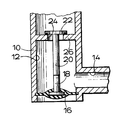
- Each valve comprises a body 10 forming a cylindrical chamber 12.
- An inlet 14 to the chamber enables air to be introduced from the blower.
- the chamber 12 and inlet 14 both form part of a fluid supply passage leading from the blower.
- a lower end of the chamber 12 (as viewed in the drawing) is closed off by a resilient diaphragm 16.
- the diaphragm 16 carries a stud 18 which projects upwards axially into the chamber 12 and forms a first component of a magnetic coupling arrangement for maintaining the valve closed; the diaphragm 16 and the stud 18 together form a displaceable operating member of biasing means of a closure mechanism of the valve.
- the upper (inner) surface of the diaphragm 16 is so exposed to the pressure within the chamber 12, and the underside is subjected to atmospheric pressure.
- a second component of the magnetic coupling arrangement comprises an axially depending stem 20 of a closure element of the closure mechanism.
- the closure element comprises an enlarged head 22 positioned above an opening 24 in an upper end wall 26 of the chamber 12; the opening 24 forms an outlet from the supply passage from the blower.
- a seating is formed upon an upper surface of the wall 26 around the opening 24, and an annular lower surface of the head 22 is arranged to bear down against the seating to seal the opening 24 when the valve is in a closed condition.
- the stem 20 of the closure element extends down from the head 22, through the opening 24, to a position adjacent to the upper end of the upwardly and oppositely projecting stud 18.
- One or other, or both, of a lower end portion of the stem 20 and an opposing upper end portion of the stud 18 are suitably magnetised so as to be attracted to one another.
- the two are drawn together to load the resilient diaphragm 16 of the operating member upwards and the head 2 of the closure element downwards on to the seating.
- the head 22 is so loaded by the upwardly displaced operating member to bear down firmly on the seating and create a good seal, the stud 18 and stem 20 being joined together by the magnetic coupling.
- the effective area of the displaceable operating member exposed to the supply passage is greater than the effective area of the closure element exposed to the passage in the closed condition of the valve.
- the force urging outwards (downwards) displacement of the operating member when the chamber 12 is pressurised is therefore greater than the force urging outwards (upwards) displacement of the closure element (i.e. to lift the closure element from its seating).
- the force on the operating member is sufficient to displace the diaphragm 16 and stud 18 downwards away from the stem 20 of the closure element and break the magnetic coupling; the closure element cannot be displaced downwards since its head 22 bears against the seating.
- the supply pressure acts to lift the closure element off the valve seating to open the valve.
- the resilient diaphragm 16 Upon the air supply pressure falling away when the blower is switched off, the resilient diaphragm 16 returns (rises) to its relaxed condition and the closure element falls (or is urged by bath water pressure) back on to the seating to prevent any return flow through the valve.
- the stem 20 and the stud 18 so come sufficiently close together for the magnetic coupling to become effective once again, drawing the two together and urging the head of the closure element down firmly against the seating.
Landscapes
- Health & Medical Sciences (AREA)
- Public Health (AREA)
- General Engineering & Computer Science (AREA)
- Engineering & Computer Science (AREA)
- Life Sciences & Earth Sciences (AREA)
- Rehabilitation Therapy (AREA)
- Physical Education & Sports Medicine (AREA)
- Animal Behavior & Ethology (AREA)
- General Health & Medical Sciences (AREA)
- Veterinary Medicine (AREA)
- Pain & Pain Management (AREA)
- Epidemiology (AREA)
- Mechanical Engineering (AREA)
- Percussion Or Vibration Massage (AREA)
Applications Claiming Priority (2)
| Application Number | Priority Date | Filing Date | Title |
|---|---|---|---|
| GB8917838 | 1989-08-04 | ||
| GB8917838A GB8917838D0 (en) | 1989-08-04 | 1989-08-04 | Non-return valve |
Publications (2)
| Publication Number | Publication Date |
|---|---|
| EP0411930A2 true EP0411930A2 (de) | 1991-02-06 |
| EP0411930A3 EP0411930A3 (en) | 1991-07-10 |
Family
ID=10661150
Family Applications (1)
| Application Number | Title | Priority Date | Filing Date |
|---|---|---|---|
| EP19900308481 Withdrawn EP0411930A3 (en) | 1989-08-04 | 1990-08-01 | Air spa or whirlpool bath system and non-return valve for use therein |
Country Status (2)
| Country | Link |
|---|---|
| EP (1) | EP0411930A3 (de) |
| GB (1) | GB8917838D0 (de) |
Cited By (2)
| Publication number | Priority date | Publication date | Assignee | Title |
|---|---|---|---|---|
| EP0503239A1 (de) * | 1991-03-15 | 1992-09-16 | Ucosan B.V. | Wanne, insbesondere Sanitärwanne, mit Luftsprudeleinrichtung |
| US5381563A (en) * | 1992-12-24 | 1995-01-17 | Roger Carrier | Check valve, and hydromassaging apparatus comprising at least one of such a check valve |
Family Cites Families (4)
| Publication number | Priority date | Publication date | Assignee | Title |
|---|---|---|---|---|
| AT59246B (de) * | 1910-02-05 | 1913-05-26 | Reinhold Breitkreuz | Rückschlagventil. |
| GB1507743A (en) * | 1976-06-22 | 1978-04-19 | British Gas Corp | Non-return valves |
| DE3240118C1 (de) * | 1982-10-29 | 1983-11-24 | Metronic Electronic GmbH, 7210 Rottweil | Rückflußverhinderungsventil |
| GB2139491A (en) * | 1983-05-12 | 1984-11-14 | Leigh Stewart Prod | Bathing apparatus |
-
1989
- 1989-08-04 GB GB8917838A patent/GB8917838D0/en active Pending
-
1990
- 1990-08-01 EP EP19900308481 patent/EP0411930A3/en not_active Withdrawn
Cited By (3)
| Publication number | Priority date | Publication date | Assignee | Title |
|---|---|---|---|---|
| EP0503239A1 (de) * | 1991-03-15 | 1992-09-16 | Ucosan B.V. | Wanne, insbesondere Sanitärwanne, mit Luftsprudeleinrichtung |
| DE4108364A1 (de) * | 1991-03-15 | 1992-09-17 | Ucosan Bv | Wanne, insbesondere sanitaerwanne, mit luftsprudeleinrichtung |
| US5381563A (en) * | 1992-12-24 | 1995-01-17 | Roger Carrier | Check valve, and hydromassaging apparatus comprising at least one of such a check valve |
Also Published As
| Publication number | Publication date |
|---|---|
| EP0411930A3 (en) | 1991-07-10 |
| GB8917838D0 (en) | 1989-09-20 |
Similar Documents
| Publication | Publication Date | Title |
|---|---|---|
| CA1070215A (en) | Reed valve | |
| ATE172282T1 (de) | Kükenhahn | |
| DE59303865D1 (de) | Kugelhahn | |
| KR880007956A (ko) | 차단용 온/오프 밸브 | |
| ATE84665T1 (de) | Vieh-traenkventil. | |
| NZ238276A (en) | Valve apparatus with diaphragm between rotatable body with wing and chamber | |
| JPS6449780A (en) | Valve | |
| EP0411930A2 (de) | Schwimmbad oder Wirbelbeckensystem und Rückschlagventil dafür | |
| ATE31797T1 (de) | Schieber. | |
| EP0311967B1 (de) | Hydromassage-Armatur mit automatischer Schliessvorrichtung | |
| CA2107591A1 (en) | Resuscitation mask | |
| FR2506888A1 (fr) | Vanne d'arret a fermeture rapide | |
| EP0372642B1 (de) | Hydro-Massagedüse für Wasserbecken | |
| ES2063969T3 (es) | Conector y disposicion de acoplamiento desconectable para un recipiente de fluido. | |
| JPH0218425Y2 (de) | ||
| SE9003674D0 (sv) | Ventil foer tvaa- eller flervaegsfloedesrglering | |
| SE8702544D0 (sv) | Ledningsbrottsventil | |
| JPH0523646Y2 (de) | ||
| JPH02612Y2 (de) | ||
| JPH0718505B2 (ja) | パイロット弁 | |
| JPH0514055Y2 (de) | ||
| JP2603048Y2 (ja) | 開閉弁 | |
| JPH0741998Y2 (ja) | フリーフロート弁 | |
| ATE111615T1 (de) | 2-wege-stromventil. | |
| JP3019339U (ja) | ダイヤフラム弁 |
Legal Events
| Date | Code | Title | Description |
|---|---|---|---|
| PUAI | Public reference made under article 153(3) epc to a published international application that has entered the european phase |
Free format text: ORIGINAL CODE: 0009012 |
|
| AK | Designated contracting states |
Kind code of ref document: A2 Designated state(s): AT BE CH DE DK ES FR GB IT LI NL |
|
| PUAL | Search report despatched |
Free format text: ORIGINAL CODE: 0009013 |
|
| AK | Designated contracting states |
Kind code of ref document: A3 Designated state(s): AT BE CH DE DK ES FR GB IT LI NL |
|
| STAA | Information on the status of an ep patent application or granted ep patent |
Free format text: STATUS: THE APPLICATION IS DEEMED TO BE WITHDRAWN |
|
| 18D | Application deemed to be withdrawn |
Effective date: 19910113 |
|
| PGFP | Annual fee paid to national office [announced via postgrant information from national office to epo] |
Ref country code: LU Payment date: 19941001 Year of fee payment: 6 |
|
| EPTA | Lu: last paid annual fee |