EP0412083B1 - Apparatus for sterilizing objects, in particular dental and medical utensils - Google Patents
Apparatus for sterilizing objects, in particular dental and medical utensils Download PDFInfo
- Publication number
- EP0412083B1 EP0412083B1 EP88908945A EP88908945A EP0412083B1 EP 0412083 B1 EP0412083 B1 EP 0412083B1 EP 88908945 A EP88908945 A EP 88908945A EP 88908945 A EP88908945 A EP 88908945A EP 0412083 B1 EP0412083 B1 EP 0412083B1
- Authority
- EP
- European Patent Office
- Prior art keywords
- container part
- wall
- chamber
- temperature
- electrically conducting
- Prior art date
- Legal status (The legal status is an assumption and is not a legal conclusion. Google has not performed a legal analysis and makes no representation as to the accuracy of the status listed.)
- Expired - Lifetime
Links
Images

Classifications
-
- A—HUMAN NECESSITIES
- A61—MEDICAL OR VETERINARY SCIENCE; HYGIENE
- A61L—METHODS OR APPARATUS FOR STERILISING MATERIALS OR OBJECTS IN GENERAL; DISINFECTION, STERILISATION OR DEODORISATION OF AIR; CHEMICAL ASPECTS OF BANDAGES, DRESSINGS, ABSORBENT PADS OR SURGICAL ARTICLES; MATERIALS FOR BANDAGES, DRESSINGS, ABSORBENT PADS OR SURGICAL ARTICLES
- A61L2/00—Disinfection or sterilisation of materials or objects, in general; Accessories therefor
- A61L2/02—Disinfection or sterilisation of materials or objects, in general; Accessories therefor using physical processes
- A61L2/04—Heat
- A61L2/06—Hot gas
- A61L2/07—Steam
Definitions
- Apparatus for sterilizing objects in particular dental and medical utensils.
- the present invention relates to an apparatus for sterilizing objects, in particular dental and medical utensils, and otherwise of the type defined in the opening clause of claim 1.
- Typical autoclaving conditions are temperatures in the range of 120-140 degrees celsius with associated steam pressures in the range of 1-3 bars overpressure. At such conditions the sterilization phase itself requires a period of time from about 20 min. (at 120 degrees celsius) and down to about 5 min. (at 140 degrees celsius). In addition there are substantial time consumptions for a preceding heat-up and stabilisation period and for a subsequent cool-down period.
- the durations of the heat-up and cool-down periods are determined by the construction of the autoclave equipment.
- Conventional autoclaves for every day use in clinics are bulky and heavy structures with quite thick chamber walls in which electrical resistance heating wires are embedded.
- the slow and frequently insufficient control and regulation of the chamber temperature is also a substantial drawback of conventional autoclaves.
- the temperature anywhere in the chamber must reach the desired sterilization temperature (for example 120 degrees celsius) throughout the complete sterilization period (for example 20 min.).
- the desired sterilization temperature for example 120 degrees celsius
- the complete sterilization period for example 20 min.
- the temperature at no time and at no place in the chamber rises substantially above the desired pre-set value. The result of even shorter temperature increases to overtemperatures may be thermal damages to temperature sensitive elements, such as objects or instrument parts made of plastic.
- the reasons are the heavy chamber walls which are difficult to give and to maintain at a constant uniform surface temperature anywhere in the chamber.
- the chamber volume usually used has a shape and size which make it difficult to provide and maintain a uniform temperature distribution in the interior of the chamber by means of heating elements which are embedded in the chamber walls.
- the invention provides a sterilizer apparatus which is characterized by the features defined in the characterizing clause of claim 1.
- the chamber defining walls can be utilized as heating element.
- a wall surface temperature which is substantially more uniform compared to conventional constructions, wherein a number of wire shaped or rod shaped heating elements are embedded more or less uniformly distributed in the chamber walls.
- the uniform surface temperature is provided directly as a consequence of the design of the heating element, and hence without any need of supplementing and surrounding the heating element with thick temperature - smoothing walls, such as is the case in conventional autoclaves.
- the complete container structure can in other words be made as a thin-walled structure with low heat capacity.
- the apparatus of the invention can be heated to and stabilized at a desired sterilization temperature within a very few minutes.
- the sterilization temperature can be maintained with a very short response time in the temperature controlling and, consequently, with a higher accuracy.
- the electrically conducting wall is tubular and is provided with electrical connectors or terminals at opposite ends thereof.
- the electrically conducting wall is defining an inner wall of the container part. This means that the chamber - defining walls can be defined directly by the conducting wall which operates as heating element.
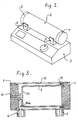
- FIG. 1 is showing a sterilizer apparatus 1 according to this invention.
- the main constituent parts are a container part 2 and a power supply and controller unit 3.
- the container part as shown is tubular with closed ends of which at least one end is arranged as a removable end cover 4. As shown the other end may be closed by means of a similar end cover 5 which, however, does not have to be removable. With end cover 4 correctly seated the container part 2 will be closed in a pressure-proof manner.
- the container part 2 is arranged with two supports 6, 7 which also include means for providing respective electric connections with the supply unit 3.
- the supports 6, 7 are permanently attached to the container part.
- the connections with the supply unit 3 are preferably detachable, so that the container part 2 can be released and be lifted free of the unit 3.
- the container part 2 comprises a special inner tube 8 which, together with the end covers 4, 5 defines a sterilization chamber.
- the inner tube 8 is also utilized as electric resistance heating element.
- the inner tube 8 is provided with respective electrical connections at the opposite tube ends.
- each of these connections comprises an annular tube part 9 and a contact member 10 connected therewith.
- the contact member 10 extends into the interior of a slot or cavity in the corresponding support 6, 7, respectively.
- Each of the annular tube parts 9 has a bigger wall thickness than the inner tube 8 so that an electric current supplied through the contact member 10, will be effectively and uniformly distributed circumferentially of the inner tube 8. The result is a uniform current density through the entire cross section of the inner tube.
- the inner tube 8 is made of an electrically conducting material, preferably of stainless steel.
- the inner tube 8 has a relatively small wall thickness, for example 0.2 mm.
- the appropriate wall thickness has been provided by turning down the tube 8, whereby the respective tube end parts 9 can be made at the same time.
- each of the end parts 9 can be a separately made ring which has been permanently attached to the respective ends of the thinner tube 8.
- the inner tube 8 is inserted coaxially in a surrounding outer tube 11, and electrically insulating spacer members 12 are keeping the two tubes separated.
- electrically insulating spacer members 12 are keeping the two tubes separated.
- an outer tube or a corresponding outer casing is not necessary, but is preferred for practical reasons.
- the outer tube 11 may be made of metal or of plastic materials, and the spacing between the inner and outer tubes may be filled with an appropriate heat insulating material. In the spacing there may, moreover, be arranged one or more temperature sensors 13 which communicate with respective associated plug sockets 14 in the supports 6, 7 through respective wires.
- the supports 6, 7 and the end covers 4, 5 are preferably made of an appropriate temperature resistant plastic material.
- one of the end covers may be permanently attached, and it may, moreover, be provided with means (not shown) for measuring or indicating the pressure in the interior of the container part 2.
- this end cover may be provided with valve means for manual and/or automatical relief of the pressure in the container part.
- the other, removable end cover 4 must close in a pressure-proof manner, and it has not shown locking means which are releasable, for example by turning the end cover.
- FIG. 3 shows schematically an alternative embodiment of the removable container part 2.
- the inner tube 8 is still a thin-walled tube which also operates as electric resistance heating element.
- One end of the inner tube is however provided with a permanent end plate 15 which centrally carries an axially projecting pin or stud 16.
- the stud 16 is in connection with a contact member 10a in figure 2 and extending into the support 6.
- the stud 16 may be shaped as a pipe spigot communicating with the chamber in the inner tube 8. Thereby the stud or spigot 16 can be part of the above mentioned means for measuring and relieving the pressure in the chamber.
- the opposite end of the inner tube 8 is permanently connected with the outer tube 11 by means of a spacer ring 17 which also serves as current distributor ring similar to the tube end part 9 in figure 2.
- the spacer ring 17 is in connection with the contact member in the support 7.
- Each of the supports 6, 7 is arranged as an electric plug or connector for removable connection with a corresponding connector or socket on the power supply and controller unit 3.
- the schematically shown embodiment of the unit 3 includes respective recesses 18 which can receive the supports 6, 7.
- a resilient contact tongue 19, 20 respectively which, when the supports have been seated, extends along the associated contact member 10, but separated therefrom.
- the socket 14, and other similar plugs if any, are engaging respective corresponding plug means 14a.
- the contact tongues 19, 20 are pressed or bent to engage the contact members 10.
- the contact tongues and contact members may also be designed to provide mechanical retainment of the supports 6, 7 and, thereby, of the complete container part 2 relative to the supply unit 3.
- the release of the locking mechanism takes place automatically, when an adjustable time period which corresponds to a desired sterilization period, has expired.
- an adjustable time period which corresponds to a desired sterilization period
- the schematically shown locking mechanism comprises two push rods 21, 22, each rod having one end in engagement with the periphery of an elliptical disk 23 which can be rotated manually in order to push the rods axially outwardly for engaging the respective contact tongues 19, 20.
- respective return springs 24, 25 and a not shown torsion spring tends to rotate the disk 23 back to its start position.
- the locking mechanism is retained in activated condition by means of a not shown latch which is electrically controlled. When the latch releases, the respective springs will bring the locking mechanism back to its start condition, wherein the container part 2 is free to be removed.
- the locking mechanism must not provide any possibility of short-circuiting between the contact tongues 19, 20.
- the push rods 21, 22 can therefor appropriately be made completely or in part of plastic material.
- the contact tongues 19, 20 are connected with the secondary side of a transformer in the supply unit 3 which also includes appropriate control and regulating circuits which are able to communicate with the container part 2 through plug connectors similar to socket 14 and plug 14a.
- the objects are placed for sterilization in the container part 2, and an appropriate dosage of water is introduced into the sterilization chamber.
- the water can be introduced by removing the end cover 4 or through a special conduit in that cover. In either case the dosing can appropriately be made by means of a hypodermic syringe.
- the charged and closed container part 2 is placed on the supply unit 3, and the desired sterilization period and temperature is adjusted. Then the locking mechanism is activated by turning the disk 23, and the process starts.
- the introduced quantity of water will evaporate and create a pressure corresponding to the steam pressure at the pre-set temperature.
- the container part 2 When the pre-set period of time has expired, the container part 2 will be released, and it can be replaced by another container part which can be sterilized while the first container part is placed for cooling.
- the container parts are also well-suited for storing and transporting the sterilized instruments.
- the heat-up and cool-down periods can be reduced to a few minutes. Moreover, the result is a very uniform and precisely controlled temperature during the sterilization period, whereby excess temperatures are effectively avoided.
- this invention provides a sterilizer which is very useful and suitable for daily use in clinics compared to conventional autoclaves which, in addition, involve substantially bigger investments in equipment and instruments.
Landscapes
- Health & Medical Sciences (AREA)
- Epidemiology (AREA)
- Life Sciences & Earth Sciences (AREA)
- Animal Behavior & Ethology (AREA)
- General Health & Medical Sciences (AREA)
- Public Health (AREA)
- Veterinary Medicine (AREA)
- Apparatus For Disinfection Or Sterilisation (AREA)
- Dental Tools And Instruments Or Auxiliary Dental Instruments (AREA)
- Food Preservation Except Freezing, Refrigeration, And Drying (AREA)
Priority Applications (1)
| Application Number | Priority Date | Filing Date | Title |
|---|---|---|---|
| AT88908945T ATE79766T1 (de) | 1987-10-02 | 1988-10-03 | Sterilisierungsvorrichtung, insbesondere fuer zahnaerztliche und aerztliche gegenstaende. |
Applications Claiming Priority (2)
| Application Number | Priority Date | Filing Date | Title |
|---|---|---|---|
| DK5174/87 | 1987-10-02 | ||
| DK517487A DK163033C (da) | 1987-10-02 | 1987-10-02 | Apparat til sterilisation af genstande isaer laege- og tandlaegeinstrumenter |
Publications (2)
| Publication Number | Publication Date |
|---|---|
| EP0412083A1 EP0412083A1 (en) | 1991-02-13 |
| EP0412083B1 true EP0412083B1 (en) | 1992-08-26 |
Family
ID=8140131
Family Applications (1)
| Application Number | Title | Priority Date | Filing Date |
|---|---|---|---|
| EP88908945A Expired - Lifetime EP0412083B1 (en) | 1987-10-02 | 1988-10-03 | Apparatus for sterilizing objects, in particular dental and medical utensils |
Country Status (9)
| Country | Link |
|---|---|
| US (1) | US5252303A (da) |
| EP (1) | EP0412083B1 (da) |
| JP (1) | JP2783569B2 (da) |
| KR (1) | KR970001493B1 (da) |
| AT (1) | ATE79766T1 (da) |
| BR (1) | BR8807226A (da) |
| DE (1) | DE3874151T2 (da) |
| DK (1) | DK163033C (da) |
| WO (1) | WO1989002753A1 (da) |
Families Citing this family (25)
| Publication number | Priority date | Publication date | Assignee | Title |
|---|---|---|---|---|
| GB2283915B (en) * | 1992-08-18 | 1996-06-05 | Blixta Griffiths Pty Ltd | Steriliser |
| AU670615B2 (en) * | 1992-08-18 | 1996-07-25 | Blixta Griffiths Pty. Limited | Steriliser |
| US5506931A (en) * | 1994-03-09 | 1996-04-09 | The Commonwealth Of Puerto Rico | Immersion type water heating element assembly with permanently wired electrical supply |
| US5733263A (en) * | 1994-09-20 | 1998-03-31 | Cabot Technology Corporation | Thermal retention system and method |
| IT1274396B (it) * | 1995-04-28 | 1997-07-17 | M O Com S R L | Procedimento ed impianto di sterilizzazione a vapore in particolare per autoclavi |
| IL115130A (en) * | 1995-09-01 | 1999-09-22 | Israel State | Method and device for ozone sterilization of objects |
| FR2740222B1 (fr) * | 1995-10-23 | 1997-11-14 | Bio Merieux | Ensemble de traitement d'un echantillon en milieu liquide, notamment d'un materiel biologique |
| US6495100B1 (en) * | 1996-04-04 | 2002-12-17 | Ethicon, Inc. | Method for sterilizing devices in a container |
| US20040221810A1 (en) * | 2002-06-28 | 2004-11-11 | Miles Ronald O. | Process boat and shell for wafer processing |
| DE60220672T2 (de) * | 2002-08-28 | 2008-03-06 | Getinge Skärhamn AB | Kompakte Sterilisations- oder Desinfektionsvorrichtung |
| US7300637B2 (en) * | 2002-09-30 | 2007-11-27 | Ethicon, Inc. | Sterilization container kit |
| US20040062693A1 (en) * | 2002-09-30 | 2004-04-01 | Szu-Min Lin | Sterilization container with a sealable filtered opening |
| KR100643260B1 (ko) * | 2004-12-14 | 2006-11-10 | 김형우 | 순간 가열 방식의 병원균 멸균장치 |
| US7113696B1 (en) | 2004-12-16 | 2006-09-26 | Mitchell Altman | System and method for generating steam for a steam bath |
| US8236253B2 (en) * | 2007-04-30 | 2012-08-07 | Midmark Corporation | Portable sterilizing apparatus for surgical and dental instruments |
| JP2008299425A (ja) * | 2007-05-29 | 2008-12-11 | Toshiba Corp | データ転送装置及びデータ転送方法 |
| USD603053S1 (en) | 2008-04-30 | 2009-10-27 | Midmark Corporation | Portable sterilizing apparatus |
| USD598565S1 (en) | 2008-04-30 | 2009-08-18 | Midmark Corporation | External condensation tank for a sterilizer |
| USD598564S1 (en) | 2008-04-30 | 2009-08-18 | Midmark Corporation | Handle for portable sterilizing apparatus |
| CN101670121A (zh) * | 2008-09-11 | 2010-03-17 | 李辉 | 蒸汽柜 |
| CN101721723A (zh) * | 2008-10-31 | 2010-06-09 | 冯炎好 | 利用高温蒸汽杀菌消毒的方法及实现该方法的消毒柜 |
| DE102011117460A1 (de) * | 2011-11-02 | 2013-05-02 | Volkswagen Aktiengesellschaft | Vorrichtung und Verfahren zum Autoklavieren von Bauteilen |
| EP2879720A4 (en) * | 2012-07-30 | 2016-03-23 | Milton E Pedrazzi | Saturated steam sterilization apparatus and method with improved stauration reliability |
| AT514562B1 (de) * | 2013-08-14 | 2015-02-15 | Anton Paar Gmbh | Autoklav |
| IT202100007226A1 (it) * | 2021-03-25 | 2022-09-25 | Cisa Production S R L | Contenitore utilizzabile per la sterilizzazione di strumenti chirurgici. |
Family Cites Families (12)
| Publication number | Priority date | Publication date | Assignee | Title |
|---|---|---|---|---|
| GB189818083A (en) * | 1898-08-23 | 1898-10-15 | Theodore Young Kinne | Improvements in Sterilized Surgical Dressing, and the Process and Apparatus for Producing the same. |
| US3436171A (en) * | 1965-06-25 | 1969-04-01 | Biolog Research Inc | Device for sterilizing inoculation needles and loops |
| US3861872A (en) * | 1973-04-02 | 1975-01-21 | Sybron Corp | Steam sterilizer |
| US4331859A (en) * | 1980-11-28 | 1982-05-25 | Ryder International Corporation | Device for sterilizing false teeth |
| DE3261561D1 (en) * | 1982-01-08 | 1985-01-31 | Ernst Haage Apparatebau Und La | Heatable high-pressure autoclave |
| US4419568A (en) * | 1982-07-12 | 1983-12-06 | The Kendall Company | Wet dressings heater |
| DE3236635A1 (de) * | 1982-10-04 | 1984-04-05 | E M D A Fabrik elektro-medizinischer und dentaler Apparate Georg Hartmann GmbH & Co KG, 6000 Frankfurt | Dampfsterilisator |
| FR2544879B1 (fr) * | 1983-04-21 | 1987-06-12 | Prat Jacques | Dispositif pour le nettoyage et la sterilisation thermique de lentilles de contact souples hydrophiles |
| US4481410A (en) * | 1983-09-27 | 1984-11-06 | Bortnick Kenneth A | Fail safe sterilizing apparatus and a circuit therefor |
| DE3516495A1 (de) * | 1985-05-08 | 1986-11-13 | Aesculap-Werke Ag Vormals Jetter & Scheerer, 7200 Tuttlingen | Heizkoerper fuer einen sterilisierkessel |
| US4659911A (en) * | 1985-05-14 | 1987-04-21 | Ryder International Corporation | Plug-in contact lens disinfector with bimetallic timer |
| US4578566A (en) * | 1985-05-28 | 1986-03-25 | Bowen John G | Soft contact lens disinfecting unit |
-
1987
- 1987-10-02 DK DK517487A patent/DK163033C/da not_active IP Right Cessation
-
1988
- 1988-10-03 JP JP63508268A patent/JP2783569B2/ja not_active Expired - Lifetime
- 1988-10-03 WO PCT/DK1988/000160 patent/WO1989002753A1/en not_active Ceased
- 1988-10-03 BR BR888807226A patent/BR8807226A/pt not_active Application Discontinuation
- 1988-10-03 AT AT88908945T patent/ATE79766T1/de not_active IP Right Cessation
- 1988-10-03 EP EP88908945A patent/EP0412083B1/en not_active Expired - Lifetime
- 1988-10-03 DE DE8888908945T patent/DE3874151T2/de not_active Expired - Fee Related
- 1988-10-03 KR KR1019890700985A patent/KR970001493B1/ko not_active Expired - Fee Related
-
1992
- 1992-06-09 US US07/896,742 patent/US5252303A/en not_active Expired - Fee Related
Also Published As
| Publication number | Publication date |
|---|---|
| WO1989002753A1 (en) | 1989-04-06 |
| US5252303A (en) | 1993-10-12 |
| KR890701140A (ko) | 1989-12-19 |
| ATE79766T1 (de) | 1992-09-15 |
| EP0412083A1 (en) | 1991-02-13 |
| DK163033C (da) | 1992-06-15 |
| DK163033B (da) | 1992-01-13 |
| DE3874151T2 (de) | 1993-01-07 |
| DE3874151D1 (de) | 1992-10-01 |
| JP2783569B2 (ja) | 1998-08-06 |
| JPH02501362A (ja) | 1990-05-17 |
| BR8807226A (pt) | 1989-10-31 |
| DK517487D0 (da) | 1987-10-02 |
| KR970001493B1 (ko) | 1997-02-11 |
| DK517487A (da) | 1989-04-03 |
Similar Documents
| Publication | Publication Date | Title |
|---|---|---|
| EP0412083B1 (en) | Apparatus for sterilizing objects, in particular dental and medical utensils | |
| US5520892A (en) | Sterilization unit for dental handpieces and other instruments | |
| US5129033A (en) | Disposable thermostatically controlled electric surgical-medical irrigation and lavage liquid warming bowl and method of use | |
| JP2006528049A (ja) | 使い捨てカートリッジ及び歯肉塞子 | |
| WO1994000077A1 (en) | Water heater for use with dental equipment | |
| CA1221810A (en) | Method of and apparatus for sterilizing devices | |
| US20190381202A1 (en) | Saturated steam sterilization device and process having improved sterilization reliability and temperature control | |
| US7015423B2 (en) | Heating device for dental material | |
| WO2014021921A2 (en) | Saturated steam sterilization device and process having improved sterilization reliability | |
| IL127991A (en) | Sterilisation apparatus | |
| JPS6134824B2 (da) | ||
| US5396049A (en) | Sterilization apparatus using electrically heated inert material as sterilizing media | |
| RU2627678C2 (ru) | Устройство для инъекции разогретой гуттаперчи в канал зуба | |
| US5148004A (en) | Contaminated needle sterilizer | |
| JPH08500038A (ja) | 滅菌装置 | |
| US2294087A (en) | Sterilizer | |
| US20050048435A1 (en) | Canal filling method and device for providing the filling product | |
| EP0588304A1 (en) | Heating assembly for dental materials | |
| CN213311584U (zh) | 一种中医药用熏蒸装置 | |
| Ihrig | Syringe sterilizer | |
| JP2007503854A (ja) | 単一又は複数の非経口溶液用容器セット内の流体の加熱及び温度監視システム | |
| JP2007503854A6 (ja) | 単一又は複数の非経口溶液用容器セット内の流体の加熱及び温度監視システム | |
| RU2064732C1 (ru) | Нагреватель текучей среды | |
| KR200417423Y1 (ko) | 의료기구의 가온장치. | |
| JPH05345012A (ja) | 汚染された注射針の殺菌消毒器具とそれを用いた殺菌消毒方法 |
Legal Events
| Date | Code | Title | Description |
|---|---|---|---|
| PUAI | Public reference made under article 153(3) epc to a published international application that has entered the european phase |
Free format text: ORIGINAL CODE: 0009012 |
|
| 17P | Request for examination filed |
Effective date: 19891006 |
|
| AK | Designated contracting states |
Kind code of ref document: A1 Designated state(s): AT BE CH DE FR GB IT LI LU NL SE |
|
| 17Q | First examination report despatched |
Effective date: 19911030 |
|
| GRAA | (expected) grant |
Free format text: ORIGINAL CODE: 0009210 |
|
| ITF | It: translation for a ep patent filed | ||
| AK | Designated contracting states |
Kind code of ref document: B1 Designated state(s): AT BE CH DE FR GB IT LI LU NL SE |
|
| REF | Corresponds to: |
Ref document number: 79766 Country of ref document: AT Date of ref document: 19920915 Kind code of ref document: T |
|
| REF | Corresponds to: |
Ref document number: 3874151 Country of ref document: DE Date of ref document: 19921001 |
|
| PGFP | Annual fee paid to national office [announced via postgrant information from national office to epo] |
Ref country code: LU Payment date: 19921014 Year of fee payment: 5 |
|
| ET | Fr: translation filed | ||
| EPTA | Lu: last paid annual fee | ||
| PLBE | No opposition filed within time limit |
Free format text: ORIGINAL CODE: 0009261 |
|
| STAA | Information on the status of an ep patent application or granted ep patent |
Free format text: STATUS: NO OPPOSITION FILED WITHIN TIME LIMIT |
|
| 26N | No opposition filed | ||
| PG25 | Lapsed in a contracting state [announced via postgrant information from national office to epo] |
Ref country code: LU Free format text: LAPSE BECAUSE OF NON-PAYMENT OF DUE FEES Effective date: 19931003 |
|
| EAL | Se: european patent in force in sweden |
Ref document number: 88908945.4 |
|
| PGFP | Annual fee paid to national office [announced via postgrant information from national office to epo] |
Ref country code: BE Payment date: 19951011 Year of fee payment: 8 |
|
| PG25 | Lapsed in a contracting state [announced via postgrant information from national office to epo] |
Ref country code: BE Effective date: 19961031 |
|
| BERE | Be: lapsed |
Owner name: GOOF SVEN KARL LENNART Effective date: 19961031 |
|
| PGFP | Annual fee paid to national office [announced via postgrant information from national office to epo] |
Ref country code: AT Payment date: 19981006 Year of fee payment: 11 |
|
| PGFP | Annual fee paid to national office [announced via postgrant information from national office to epo] |
Ref country code: NL Payment date: 19981031 Year of fee payment: 11 |
|
| PGFP | Annual fee paid to national office [announced via postgrant information from national office to epo] |
Ref country code: CH Payment date: 19981110 Year of fee payment: 11 |
|
| PGFP | Annual fee paid to national office [announced via postgrant information from national office to epo] |
Ref country code: GB Payment date: 19990920 Year of fee payment: 12 |
|
| PG25 | Lapsed in a contracting state [announced via postgrant information from national office to epo] |
Ref country code: AT Free format text: LAPSE BECAUSE OF NON-PAYMENT OF DUE FEES Effective date: 19991003 |
|
| PGFP | Annual fee paid to national office [announced via postgrant information from national office to epo] |
Ref country code: FR Payment date: 19991018 Year of fee payment: 12 |
|
| PGFP | Annual fee paid to national office [announced via postgrant information from national office to epo] |
Ref country code: SE Payment date: 19991025 Year of fee payment: 12 |
|
| PGFP | Annual fee paid to national office [announced via postgrant information from national office to epo] |
Ref country code: DE Payment date: 19991028 Year of fee payment: 12 |
|
| PG25 | Lapsed in a contracting state [announced via postgrant information from national office to epo] |
Ref country code: LI Free format text: LAPSE BECAUSE OF NON-PAYMENT OF DUE FEES Effective date: 19991031 Ref country code: CH Free format text: LAPSE BECAUSE OF NON-PAYMENT OF DUE FEES Effective date: 19991031 |
|
| PG25 | Lapsed in a contracting state [announced via postgrant information from national office to epo] |
Ref country code: NL Free format text: LAPSE BECAUSE OF NON-PAYMENT OF DUE FEES Effective date: 20000501 |
|
| REG | Reference to a national code |
Ref country code: CH Ref legal event code: PL |
|
| NLV4 | Nl: lapsed or anulled due to non-payment of the annual fee |
Effective date: 20000501 |
|
| PG25 | Lapsed in a contracting state [announced via postgrant information from national office to epo] |
Ref country code: GB Free format text: LAPSE BECAUSE OF NON-PAYMENT OF DUE FEES Effective date: 20001003 |
|
| PG25 | Lapsed in a contracting state [announced via postgrant information from national office to epo] |
Ref country code: SE Free format text: THE PATENT HAS BEEN ANNULLED BY A DECISION OF A NATIONAL AUTHORITY Effective date: 20001030 |
|
| GBPC | Gb: european patent ceased through non-payment of renewal fee |
Effective date: 20001003 |
|
| EUG | Se: european patent has lapsed |
Ref document number: 88908945.4 |
|
| PG25 | Lapsed in a contracting state [announced via postgrant information from national office to epo] |
Ref country code: FR Free format text: LAPSE BECAUSE OF NON-PAYMENT OF DUE FEES Effective date: 20010629 |
|
| PG25 | Lapsed in a contracting state [announced via postgrant information from national office to epo] |
Ref country code: DE Free format text: LAPSE BECAUSE OF NON-PAYMENT OF DUE FEES Effective date: 20010703 |
|
| REG | Reference to a national code |
Ref country code: FR Ref legal event code: ST |
|
| PG25 | Lapsed in a contracting state [announced via postgrant information from national office to epo] |
Ref country code: IT Free format text: LAPSE BECAUSE OF NON-PAYMENT OF DUE FEES;WARNING: LAPSES OF ITALIAN PATENTS WITH EFFECTIVE DATE BEFORE 2007 MAY HAVE OCCURRED AT ANY TIME BEFORE 2007. THE CORRECT EFFECTIVE DATE MAY BE DIFFERENT FROM THE ONE RECORDED. Effective date: 20051003 |