EP0412092B1 - Procede et appareil de production de conduites souterraines - Google Patents
Procede et appareil de production de conduites souterraines Download PDFInfo
- Publication number
- EP0412092B1 EP0412092B1 EP89904566A EP89904566A EP0412092B1 EP 0412092 B1 EP0412092 B1 EP 0412092B1 EP 89904566 A EP89904566 A EP 89904566A EP 89904566 A EP89904566 A EP 89904566A EP 0412092 B1 EP0412092 B1 EP 0412092B1
- Authority
- EP
- European Patent Office
- Prior art keywords
- tool
- tools
- tunnel
- pipe
- transportation
- Prior art date
- Legal status (The legal status is an assumption and is not a legal conclusion. Google has not performed a legal analysis and makes no representation as to the accuracy of the status listed.)
- Expired - Lifetime
Links
- 238000000034 method Methods 0.000 title claims abstract description 22
- 238000004519 manufacturing process Methods 0.000 title claims description 4
- 239000002689 soil Substances 0.000 claims abstract description 17
- 238000005520 cutting process Methods 0.000 claims abstract description 8
- 230000033001 locomotion Effects 0.000 claims abstract description 8
- 239000011435 rock Substances 0.000 claims description 8
- 238000005553 drilling Methods 0.000 claims description 7
- 230000001681 protective effect Effects 0.000 claims description 2
- 238000010276 construction Methods 0.000 description 9
- 230000032258 transport Effects 0.000 description 4
- 238000009412 basement excavation Methods 0.000 description 3
- 230000007547 defect Effects 0.000 description 3
- 239000000463 material Substances 0.000 description 3
- 238000006073 displacement reaction Methods 0.000 description 2
- 230000000694 effects Effects 0.000 description 1
- 230000000149 penetrating effect Effects 0.000 description 1
- 230000035515 penetration Effects 0.000 description 1
- 230000000007 visual effect Effects 0.000 description 1
Images


Classifications
-
- E—FIXED CONSTRUCTIONS
- E21—EARTH OR ROCK DRILLING; MINING
- E21D—SHAFTS; TUNNELS; GALLERIES; LARGE UNDERGROUND CHAMBERS
- E21D9/00—Tunnels or galleries, with or without linings; Methods or apparatus for making thereof; Layout of tunnels or galleries
- E21D9/12—Devices for removing or hauling away excavated material or spoil; Working or loading platforms
- E21D9/124—Helical conveying means therefor
-
- E—FIXED CONSTRUCTIONS
- E21—EARTH OR ROCK DRILLING; MINING
- E21B—EARTH OR ROCK DRILLING; OBTAINING OIL, GAS, WATER, SOLUBLE OR MELTABLE MATERIALS OR A SLURRY OF MINERALS FROM WELLS
- E21B7/00—Special methods or apparatus for drilling
- E21B7/04—Directional drilling
- E21B7/06—Deflecting the direction of boreholes
- E21B7/068—Deflecting the direction of boreholes drilled by a down-hole drilling motor
-
- E—FIXED CONSTRUCTIONS
- E21—EARTH OR ROCK DRILLING; MINING
- E21D—SHAFTS; TUNNELS; GALLERIES; LARGE UNDERGROUND CHAMBERS
- E21D9/00—Tunnels or galleries, with or without linings; Methods or apparatus for making thereof; Layout of tunnels or galleries
- E21D9/005—Tunnels or galleries, with or without linings; Methods or apparatus for making thereof; Layout of tunnels or galleries by forcing prefabricated elements through the ground, e.g. by pushing lining from an access pit
Definitions
- This invention relates to a method and to an apparatus for the production of tunnels for underground pipelines without moving soil above the pipeline. Soil or rocks meant to be removed are loosened by some known method. Loosened material is removed from the tunnel by a rotating transportation drum rotating on rolls inside the pipe meant to be assembled into the ground.
- soil displacing methods can be used in which the pipe is pressed in the desired direction by a force strong enough to move the pipe. In the end of the pipe there is placed a formed point which displaces the soil as much as the pipe requires.
- An apparatus based on such displacement of soil is presented in patent document FI-51726. While it is relatively easy to make small holes by this method, in case of larger diameter holes, friction against displacement becomes so strong that energy sources available to be used in this purpose, can not produce the force needed, or their use is uneconomical. Because of this, in case of larger diameter holes, one has to use mechanical hammers or cutters.
- German patent document DE 32 28 684 there is shown a construction in which the transportation screw is located in the supporting pipe whose diameter is essentially smaller than the diameter of the pipe assembled. In this case, location or direction determination of drill head can be executed through an upper area of the pipe, which is remaining free.
- the drill head can easily be observed and there is a spacious and small fractioned way to transport the loosened soil. Also, because of the large diameter transportation pipe, it is possible to transmit a large torsional moment to the drill head. While the free center of the transportation pipe is large, one can also transport through the drum for instance tools, etc. This is good when, after drilling with only the drill head in soft soil, one meets rock. Then one has to transport a hammering tool to the drill head and assemble it. Also whole rocks with diameters almost the same as the drum can be transported through the transportation drum. While drilling it is possible to observe the end of the tunnel and the quality of the ground can be seen and examined through the pipe.
- the diameter of the free hole in the middle of the transportation drum is at least 40 % of the inner diameter of the outer pipe.
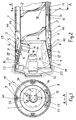
- fig. 1 is shown schematically a transportation drum 1 which is rotating on the rolls 14 of a supporting roll device 13, which roll devices are fixed in an assembled pipe 8. Hydraulic cylinders 9 guiding a drill head get their pressure through hoses 15, which are led through a lower part of pipe 8. Roll device 13 can be fixed in pipe 8.
- the cylinders 9 have been jointed with parts 43,44. Adjustment of the direction penetration is done with cylinder 9 by turning flange 6 to a desired direction. Supporting rolls 12 are fixed in cylinder part 4, which rolls are turning in relation to cylinder part 7 while the head part is turned. The flange 6 is fastened to cylinder part 5, which can slide and when needed turn in relation to cylinder part 7. Hydraulic cylinders 9 are fastened at one end to cylinder part 7 and at the other end to guiding cylinder part 5 and to flange 6. Rotating movement of head 3 is caused by inner pipe 1 which is jointed to head 3 in case of small internal differences in direction. Inner pipe 1 has an internal spiral 2, which is transporting material 19 loosened from the ground to the back of the device.
- FIG. 3 In fig. 3, is shown the head 3 of the device penetrating into the ground.
- Rotating cutters 20 and 21 are jointed in the head rotating conical part 3 with bearings, and these cutters rotate around a shaft of their own because of the rotating movement of conical part 3 and because of their own angular position.
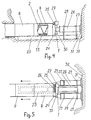
- FIGS 4 and 5 a back part of a starting hole is shown.
- the hole there is a frame construction 23 over which new outer pipe 8 parts and inner pipe 1 parts are lifted while the head 3 of the device is entering and push cylinders 28 have pushed earlier pipe parts into the hole.
- Push cylinders are supported with plates 31 and 32 to the back wall of the starting hole.
- Cylinders 28 are so jointed in to the frame construction with parts 29 that cylinders 28 are able to slide on parts 29 backwards, in case soil in the back wall of the starting hole is moving because of the push force.
- frame construction 23 can stay in its original position and this is desirable because the exact starting direction of the tunnel has been adjusted with frame construction 23.
- Cylinders 28 are pushing the outer pipe 8 with a special flange 24 with the help of adapters 30.
- a rotatable cogged part 26 which is rotated with motor 27 and cogwheel 25. Rotating cogged part 26 is quick-jointed by some known method to the adjacent inner pipe 1, which is in turn to be pushed.
- Every inner pipe is tied to the next one by a known quick-joint method, for instance with a chain, so that rotating movement is transmitted to the head part 3.
- Transporting spiral 2 transports loosened soil to the starting hole, from which the soil can be ejected. During the whole working period, the filling rate of the spiral is low, so that continuous drill head observation is possible.
- Cutting tool 38 which is fastened in the drill head 3.
- Cutting tool 38 contains a cutting head 39 and a cylinder 37 able to push to one direction and retreat to another direction.
- Tool 38 is fastened with screws 42 in holes 41 in a crosswise bar 40 jointed to the drill head 3.
- Tool 38 can cut, especially in rock, different diameter ring shape cuttings. It is possible to have several tools jointed in bar 40. It can also be possible to choose the diameter to be cut as the position of tool 38 in bar 40 can be adjusted by moving tools in bar 40 for instance with hydraulic or pneumatic pressure.
Landscapes
- Engineering & Computer Science (AREA)
- Mining & Mineral Resources (AREA)
- Life Sciences & Earth Sciences (AREA)
- Geology (AREA)
- Environmental & Geological Engineering (AREA)
- General Life Sciences & Earth Sciences (AREA)
- Geochemistry & Mineralogy (AREA)
- Physics & Mathematics (AREA)
- Fluid Mechanics (AREA)
- Excavating Of Shafts Or Tunnels (AREA)
- Earth Drilling (AREA)
Abstract
Claims (13)
- Une méthode pour produire une canalisation souterraine à partir d'un trou excavé et comprenant les phases suivantes:- assemblage successif de tubes extérieurs (8) ou de pièces cylindriques égales dans le tunnel pendant la construction du tunnel pour former la canalisation- construction du tunnel à l'aide d'un outil/des outils rotatif(s) (17,36,20,21)- transport de la terre ou roche (19) hors le tunnel à l'aide d'une hélice rotative de transport (2)- utilisation du tambour de transport (1) pour transmettre les fonctions de commande au porte-fraise (3)caractérisée par le fait que:- le tunnel se trouve foré à l'aide d'un outil ou de plusieurs outils (17,36,20,21), lesquels outils (17,36,20,21) peuvent être transportés et transférés à travers le trou central libre dans le tambour de transport (1)- le porte-fraise (3) et la face du tunnel sont observés à travers le trou libre dans le tambour de transport (1).
- Une méthode conforme à la revendication 1 caractérisée par le fait que des tuyaux flexibles (15) se trouvent conduits vers le porte-fraise (3) protégés par le cadre stabile (13) du mécanisme à rouleaux.
- Une méthode conforme aux revendications 1 et 2 caractérisées par le fait que le forage s'effectue à l'aide d'un outil au moins, dont la position radiale peut être ajustée.
- Une méthode conforme aux revendications 1 et 2 caractérisées par de fait le forage s'effectue à l'aide de deux ou plusieurs outils lorsque le porte-fraise (3) est rotatif tandis qu'au moins un outil coupe le trou central rond du tunnel et au moins un outil coupe la partie extérieure annulaire du tunnel.
- Une méthode conforme aux revendications 1 - 4 caractérisées par le fait que les bâtis des outils peuvent effectuer un mouvement de retraite contre la force causée par le matériau pressurisé.
- Une méthode conforme à l'une des revendications 1 - 5 caractérisées par le fait qu'au cours du travail de canalisation, des éléments réunis sont poussés l'un après l'autre dans le tunnel foré, lesdits éléments étant de la même longueur et comprenant un tube protecteur (8); à l'intérieur de ce tube se trouve monté un tambour de transport (1) de la même longueur que le tube ainsi qu'un système à rouleaux (14) avec cadre (13) entre ledit tube et ledit tambour.
- Une méthode conforme à l'une des revendications 1 - 6 caractérisées par le fait que le matériau pressurisé pour les outils (17,36,20,21) se trouve conduit à travers les tuyaux flexibles (18) qui se trouvent du côté arrière de l'hélice (2) dans le tambour de transport (1).
- Une méthode conforme à l'une des revendications 1 - 7 caractérisées par le fait que le diamètre du trou central libre dans le tambour de transport (1) est au moins la moitié du diamètre extérieur du tube extérieur (8).
- Appareillage pour réaliser la méthode confermément à la revendication 1 et comprenant- une pièce de tête rotative (3) et les cylindres (9) pour guider ladite pièce- un tambour de transport (1) avec hélice intérieur (2)- un moteur (27) qui trasmet le mouvement rotatif au cercle extérieur du tambour de transport- cylindres (28) et leurs cadres (23); les cylindres fournissent la force de poussée au porte-fraise (3) et aux tubes extérieurscaractérisée par le fait que- la pipeline du tambour de trasport qui est construite de pièces réunies l'une après l'autre dispose d'un trou central libre dont le diamètre est au moins 40 % du diamètre extérieur du tube extérieur (8)- les cadres de rouleaux (13) comprenant les dispositifs de roulage (14) supportant le tambour de transport (1) se trouvent principalement dans la partie inférieure du tube extérieur (8); ils sont supportés ou fixés sur ledit tube extérieur (8).
- Appareillage conforme à la revendication 9 caractérisée par le fait qu'il comprend un outil ou plusieurs outils (17,36,20,21) fixés sur le porte-fraise (3) ainsi que des dispositifs de serrage dans lesquels l'outil/les outils (17,36,20,21) peut/peuvent être ajusté(s) en fonction de la direction du rayon du tunnel.
- Appareillage conforme à la revendication 9 caractérisée par le fait que le porte-fraise (3) comprend un ou plusieurs outils (17,36,20,21), dont au moins un effectue le forage du trou central et au moins un celui du cercle extérieur annulaire du tunnel.
- Appareillage conforme à l'une des revendications 9 - 11 caractérisée par le fait que les dispositifs de serrage d'un ou de plusieurs outils (17,36,20,21) comprennent une glissoire pour dispositif de serrage dans lequel l'outil peut être déplacé dans la direction axiale par un cylindre actionné par le matériau pressurisé.
- Appareillage conforme à l'une des revendications 9 - 12 caractérisées par le fait que les dispositifs de serrage de l'outil/des outils (17,36,20,21) comprennent un glissoire pour dispositif de serrage dans lequel l'outil peut bouger dans la direction axiale contre la force causée par le matériau pressurisé dans un cylindre spécial (10,35,37).
Priority Applications (1)
| Application Number | Priority Date | Filing Date | Title |
|---|---|---|---|
| AT89904566T ATE99768T1 (de) | 1988-04-27 | 1989-04-11 | Vorrichtung und verfahren zur herstellung unterirdischer leitungen. |
Applications Claiming Priority (2)
| Application Number | Priority Date | Filing Date | Title |
|---|---|---|---|
| FI881964A FI881964A7 (fi) | 1988-04-27 | 1988-04-27 | Foerfarande och anordning foer att bygga underjordiska roerlinjer. |
| FI881964 | 1988-04-27 |
Publications (2)
| Publication Number | Publication Date |
|---|---|
| EP0412092A1 EP0412092A1 (fr) | 1991-02-13 |
| EP0412092B1 true EP0412092B1 (fr) | 1994-01-05 |
Family
ID=8526362
Family Applications (1)
| Application Number | Title | Priority Date | Filing Date |
|---|---|---|---|
| EP89904566A Expired - Lifetime EP0412092B1 (fr) | 1988-04-27 | 1989-04-11 | Procede et appareil de production de conduites souterraines |
Country Status (9)
| Country | Link |
|---|---|
| US (1) | US5125768A (fr) |
| EP (1) | EP0412092B1 (fr) |
| JP (1) | JPH03504524A (fr) |
| AU (1) | AU633820B2 (fr) |
| CA (1) | CA1334482C (fr) |
| DE (1) | DE68912124T2 (fr) |
| FI (1) | FI881964A7 (fr) |
| RU (1) | RU1836565C (fr) |
| WO (1) | WO1989010467A1 (fr) |
Families Citing this family (13)
| Publication number | Priority date | Publication date | Assignee | Title |
|---|---|---|---|---|
| JPH086551B2 (ja) * | 1989-07-19 | 1996-01-24 | 株式会社イセキ開発工機 | シールド型トンネル機械の方向修正装置 |
| FI86330C (fi) * | 1989-09-27 | 1992-08-10 | Valto Ilomaeki | Foerfarande och anordning foer borrning av tunnel. |
| FI86331C (fi) * | 1989-09-27 | 1992-08-10 | Valto Ilomaeki | Reglerfoerfarande foer borrmaskin och regleranordning. |
| CH683446A5 (de) * | 1991-02-25 | 1994-03-15 | Herrenknecht Gmbh | Rückholbare Tunnelvortriebsmaschine. |
| US5482404A (en) * | 1993-07-27 | 1996-01-09 | Tenbusch, Ii; Albert A. | Underground pipe replacement technique |
| US5813482A (en) * | 1995-12-26 | 1998-09-29 | Barbera; Leo J. | Earth boring system and apparatus |
| DE19620401C2 (de) * | 1996-05-21 | 1998-06-10 | Tracto Technik | Lenkbare Bohrvorrichtung |
| FI20060749A7 (fi) * | 2006-08-23 | 2008-04-28 | Hannu Paasonen | Poralaite reiän poraamiseksi tai avartamiseksi |
| US8113741B1 (en) | 2010-05-20 | 2012-02-14 | Astec Industries, Inc. | Boring machine with conveyor system for cuttings and method for boring therewith |
| US8393828B1 (en) | 2010-05-20 | 2013-03-12 | American Augers, Inc. | Boring machine steering system with force multiplier |
| US8210774B1 (en) | 2010-05-20 | 2012-07-03 | Astec Industries, Inc. | Guided boring machine and method |
| US9039330B1 (en) | 2010-06-01 | 2015-05-26 | LLAJ, Inc. | Pipe boring shield |
| US20120051843A1 (en) * | 2010-08-27 | 2012-03-01 | King Abdul Aziz City For Science And Technology | Tunnel drilling machine |
Family Cites Families (18)
| Publication number | Priority date | Publication date | Assignee | Title |
|---|---|---|---|---|
| BE649983A (fr) * | ||||
| US2821374A (en) * | 1955-11-30 | 1958-01-28 | Ingersoll Rand Canada | Coal mining machine having a pivotally mounted cutter tube |
| US2919121A (en) * | 1957-09-25 | 1959-12-29 | Joseph P Ruth | Mining and excavating machine of the rotary type |
| US2946567A (en) * | 1958-08-11 | 1960-07-26 | Robert K Pepper | Casing installing machine |
| GB1311094A (en) * | 1969-03-25 | 1973-03-21 | Dubois M | Machine and process for digging undergrojnd galleries |
| FI51726C (fi) * | 1971-01-15 | 1977-03-10 | Inst Gornogo Dela Sibirskogo O | Laite, jolla tehdään reikiä maahan |
| GB1488489A (en) * | 1974-10-30 | 1977-10-12 | Coal Ind | Excavating machines |
| SU763535A1 (ru) * | 1978-02-01 | 1980-09-15 | Институт Горного Дела Со Ан Ссср | Машина дл образовани скважин в грунте |
| FI790485A7 (fi) * | 1978-02-21 | 1979-08-22 | Frankignoul Pieux Armes | Foerfarande och anordning foer byggande av underjordiska tunlar och dylika med vertikala vaeggar |
| US4506931A (en) * | 1979-01-15 | 1985-03-26 | United States Pipe And Foundry Company | Method and apparatus for mining |
| DE2909395A1 (de) * | 1979-03-09 | 1980-09-18 | Gewerk Eisenhuette Westfalia | Schuerfeinrichtung fuer den vortrieb von tunneln, stollen oder sonstigen hohlraeumen |
| DE3000683A1 (de) * | 1979-08-01 | 1981-07-16 | Salzgitter Maschinen Und Anlagen Ag, 3320 Salzgitter | Lafettenbohrgeraet |
| GB2106161B (en) * | 1981-09-18 | 1985-07-10 | Hitachi Shipbuilding Eng Co | Shield tunneling machine |
| DE3228684A1 (de) * | 1982-07-31 | 1984-02-02 | Baumann & Burmeister Bauunternehmung Gmbh & Co Kg, 2000 Hamburg | Vorrichtung zum vorpressen kleiner, nicht mehr begehbarer rohre |
| DE3306047A1 (de) * | 1983-02-22 | 1984-08-23 | Witte Bohrtechnik GmbH, 3060 Stadthagen | Einrichtung zum steuerbaren vorpressen von rohren zur herstellung eines unterirdischen rohrvortriebes |
| DE3514563A1 (de) * | 1985-04-23 | 1986-10-30 | Strabag Bau-AG, 5000 Köln | Tunnelvortriebsmaschine |
| DE3605009A1 (de) * | 1986-02-18 | 1987-08-20 | Gewerk Eisenhuette Westfalia | Rohrvorpresseinrichtung, insbesondere zum vorpressen von rohren kleiner durchmesser |
| JPH0278698A (ja) * | 1988-09-16 | 1990-03-19 | Mitsubishi Gas Chem Co Inc | 尿素分解素子 |
-
1988
- 1988-04-27 FI FI881964A patent/FI881964A7/fi not_active Application Discontinuation
-
1989
- 1989-04-11 US US07/598,731 patent/US5125768A/en not_active Expired - Fee Related
- 1989-04-11 WO PCT/FI1989/000067 patent/WO1989010467A1/fr not_active Ceased
- 1989-04-11 DE DE68912124T patent/DE68912124T2/de not_active Expired - Fee Related
- 1989-04-11 EP EP89904566A patent/EP0412092B1/fr not_active Expired - Lifetime
- 1989-04-11 AU AU34336/89A patent/AU633820B2/en not_active Ceased
- 1989-04-11 JP JP1504124A patent/JPH03504524A/ja active Pending
- 1989-04-26 CA CA000597804A patent/CA1334482C/fr not_active Expired - Fee Related
-
1990
- 1990-10-26 RU SU904831441A patent/RU1836565C/ru active
Also Published As
| Publication number | Publication date |
|---|---|
| FI881964A0 (fi) | 1988-04-27 |
| FI881964A7 (fi) | 1989-10-28 |
| JPH03504524A (ja) | 1991-10-03 |
| RU1836565C (ru) | 1993-08-23 |
| US5125768A (en) | 1992-06-30 |
| DE68912124D1 (de) | 1994-02-17 |
| WO1989010467A1 (fr) | 1989-11-02 |
| EP0412092A1 (fr) | 1991-02-13 |
| CA1334482C (fr) | 1995-02-21 |
| DE68912124T2 (de) | 1994-07-28 |
| AU633820B2 (en) | 1993-02-11 |
| AU3433689A (en) | 1989-11-24 |
Similar Documents
| Publication | Publication Date | Title |
|---|---|---|
| US5791419A (en) | Drilling apparatus for replacing underground pipes | |
| AU2007245987B2 (en) | Method for trenchless pipeline laying | |
| CA2219642C (fr) | Procede et equipement d'enlevement d'une canalisation d'amenee et de remplacement par un tuyau en polyolefine | |
| US4526242A (en) | Drilling device | |
| US4553612A (en) | Earth boring machine | |
| US5125768A (en) | Method and apparatus for the production of underground pipelines | |
| AU666943B2 (en) | Shield tunnelling machine | |
| JPH06503624A (ja) | 特に下水管を交換する方法及びこの方法を実施するための装置 | |
| AU643707B2 (en) | Drilling apparatus and method for its control | |
| US7353889B1 (en) | Rotary driven pipe-bursting tool | |
| RU2062881C1 (ru) | Способ управления продвижением бурильной установки и устройство для его осуществления | |
| US5032039A (en) | Underground excavator | |
| US20250188805A1 (en) | Expanding drill device | |
| CZ2000277A3 (cs) | Způsob a zařízení k zamezení horským otřesům, zejména při provádění hornických prací | |
| US3693734A (en) | Boring auger for horizontal earth boring machine | |
| CA2534912C (fr) | Dispositif d'eclatement de conduite dote d'un element d'eclatement spherique | |
| US3469884A (en) | Tunnel driving shield having pivotally mounted drilling boom | |
| FI86330B (fi) | Foerfarande och anordning foer borrning av tunnel. | |
| US2804754A (en) | Apparatus for tunnelling | |
| US20110214918A1 (en) | Excavation Apparatuses and Methods | |
| FI85302B (fi) | Foerfarande och anordning foer att bygga underjordiska roerlinjer. | |
| US5984583A (en) | Methods and apparatus for directionally drilling a bore and placing pipe | |
| CN1144549A (zh) | 用于钻开隧道的设备及钻进方法 | |
| JPS6233820Y2 (fr) | ||
| Thomson | Equipment: microtunnelling |
Legal Events
| Date | Code | Title | Description |
|---|---|---|---|
| PUAI | Public reference made under article 153(3) epc to a published international application that has entered the european phase |
Free format text: ORIGINAL CODE: 0009012 |
|
| 17P | Request for examination filed |
Effective date: 19901012 |
|
| AK | Designated contracting states |
Kind code of ref document: A1 Designated state(s): AT BE CH DE FR GB IT LI NL SE |
|
| 17Q | First examination report despatched |
Effective date: 19920601 |
|
| GRAA | (expected) grant |
Free format text: ORIGINAL CODE: 0009210 |
|
| AK | Designated contracting states |
Kind code of ref document: B1 Designated state(s): AT BE CH DE FR GB IT LI NL SE |
|
| PG25 | Lapsed in a contracting state [announced via postgrant information from national office to epo] |
Ref country code: NL Effective date: 19940105 Ref country code: LI Effective date: 19940105 Ref country code: CH Effective date: 19940105 Ref country code: BE Effective date: 19940105 Ref country code: AT Effective date: 19940105 |
|
| REF | Corresponds to: |
Ref document number: 99768 Country of ref document: AT Date of ref document: 19940115 Kind code of ref document: T |
|
| REF | Corresponds to: |
Ref document number: 68912124 Country of ref document: DE Date of ref document: 19940217 |
|
| ITF | It: translation for a ep patent filed | ||
| PGFP | Annual fee paid to national office [announced via postgrant information from national office to epo] |
Ref country code: SE Payment date: 19940413 Year of fee payment: 6 |
|
| REG | Reference to a national code |
Ref country code: CH Ref legal event code: PL |
|
| ET | Fr: translation filed | ||
| NLV1 | Nl: lapsed or annulled due to failure to fulfill the requirements of art. 29p and 29m of the patents act | ||
| PLBE | No opposition filed within time limit |
Free format text: ORIGINAL CODE: 0009261 |
|
| STAA | Information on the status of an ep patent application or granted ep patent |
Free format text: STATUS: NO OPPOSITION FILED WITHIN TIME LIMIT |
|
| 26N | No opposition filed | ||
| EAL | Se: european patent in force in sweden |
Ref document number: 89904566.0 |
|
| PG25 | Lapsed in a contracting state [announced via postgrant information from national office to epo] |
Ref country code: SE Effective date: 19950412 |
|
| EUG | Se: european patent has lapsed |
Ref document number: 89904566.0 |
|
| PGFP | Annual fee paid to national office [announced via postgrant information from national office to epo] |
Ref country code: GB Payment date: 19960419 Year of fee payment: 8 |
|
| PG25 | Lapsed in a contracting state [announced via postgrant information from national office to epo] |
Ref country code: GB Effective date: 19970411 |
|
| PGFP | Annual fee paid to national office [announced via postgrant information from national office to epo] |
Ref country code: FR Payment date: 19971027 Year of fee payment: 9 |
|
| PGFP | Annual fee paid to national office [announced via postgrant information from national office to epo] |
Ref country code: DE Payment date: 19971108 Year of fee payment: 9 |
|
| GBPC | Gb: european patent ceased through non-payment of renewal fee |
Effective date: 19970411 |
|
| PG25 | Lapsed in a contracting state [announced via postgrant information from national office to epo] |
Ref country code: FR Free format text: THE PATENT HAS BEEN ANNULLED BY A DECISION OF A NATIONAL AUTHORITY Effective date: 19980430 |
|
| PG25 | Lapsed in a contracting state [announced via postgrant information from national office to epo] |
Ref country code: DE Free format text: LAPSE BECAUSE OF NON-PAYMENT OF DUE FEES Effective date: 19990202 |
|
| REG | Reference to a national code |
Ref country code: FR Ref legal event code: ST |
|
| PG25 | Lapsed in a contracting state [announced via postgrant information from national office to epo] |
Ref country code: IT Free format text: LAPSE BECAUSE OF NON-PAYMENT OF DUE FEES Effective date: 20050411 |