EP0412197A1 - Individueller Verbindungsblock zur Kompensation der kalten Lötstelle eines Thermoelementes - Google Patents
Individueller Verbindungsblock zur Kompensation der kalten Lötstelle eines Thermoelementes Download PDFInfo
- Publication number
- EP0412197A1 EP0412197A1 EP89114888A EP89114888A EP0412197A1 EP 0412197 A1 EP0412197 A1 EP 0412197A1 EP 89114888 A EP89114888 A EP 89114888A EP 89114888 A EP89114888 A EP 89114888A EP 0412197 A1 EP0412197 A1 EP 0412197A1
- Authority
- EP
- European Patent Office
- Prior art keywords
- microcircuit
- thermoelectric couple
- connection
- compensation
- cold junction
- Prior art date
- Legal status (The legal status is an assumption and is not a legal conclusion. Google has not performed a legal analysis and makes no representation as to the accuracy of the status listed.)
- Granted
Links
- 239000004020 conductor Substances 0.000 claims description 11
- 238000003466 welding Methods 0.000 claims description 9
- 239000011810 insulating material Substances 0.000 claims description 4
- BASFCYQUMIYNBI-UHFFFAOYSA-N platinum Chemical compound [Pt] BASFCYQUMIYNBI-UHFFFAOYSA-N 0.000 claims description 4
- 239000000523 sample Substances 0.000 claims description 4
- 230000033228 biological regulation Effects 0.000 claims description 2
- 238000012937 correction Methods 0.000 claims description 2
- 229910052697 platinum Inorganic materials 0.000 claims description 2
- 238000005259 measurement Methods 0.000 abstract description 10
- 229910000679 solder Inorganic materials 0.000 description 3
- 238000005476 soldering Methods 0.000 description 3
- 238000010438 heat treatment Methods 0.000 description 2
- 238000011144 upstream manufacturing Methods 0.000 description 2
- 239000004593 Epoxy Substances 0.000 description 1
- 230000005678 Seebeck effect Effects 0.000 description 1
- ATJFFYVFTNAWJD-UHFFFAOYSA-N Tin Chemical compound [Sn] ATJFFYVFTNAWJD-UHFFFAOYSA-N 0.000 description 1
- 238000004026 adhesive bonding Methods 0.000 description 1
- 230000000295 complement effect Effects 0.000 description 1
- 238000001816 cooling Methods 0.000 description 1
- 238000010586 diagram Methods 0.000 description 1
- 238000011156 evaluation Methods 0.000 description 1
- 239000011521 glass Substances 0.000 description 1
- 238000003780 insertion Methods 0.000 description 1
- 230000037431 insertion Effects 0.000 description 1
- 238000009434 installation Methods 0.000 description 1
- 238000002372 labelling Methods 0.000 description 1
- 229910052751 metal Inorganic materials 0.000 description 1
- 239000002184 metal Substances 0.000 description 1
- 238000013021 overheating Methods 0.000 description 1
- 230000010287 polarization Effects 0.000 description 1
- 230000035945 sensitivity Effects 0.000 description 1
- 229910001174 tin-lead alloy Inorganic materials 0.000 description 1
Images


Classifications
-
- G—PHYSICS
- G01—MEASURING; TESTING
- G01K—MEASURING TEMPERATURE; MEASURING QUANTITY OF HEAT; THERMALLY-SENSITIVE ELEMENTS NOT OTHERWISE PROVIDED FOR
- G01K7/00—Measuring temperature based on the use of electric or magnetic elements directly sensitive to heat ; Power supply therefor, e.g. using thermoelectric elements
- G01K7/02—Measuring temperature based on the use of electric or magnetic elements directly sensitive to heat ; Power supply therefor, e.g. using thermoelectric elements using thermoelectric elements, e.g. thermocouples
- G01K7/023—Measuring temperature based on the use of electric or magnetic elements directly sensitive to heat ; Power supply therefor, e.g. using thermoelectric elements using thermoelectric elements, e.g. thermocouples provided with specially adapted connectors
-
- G—PHYSICS
- G01—MEASURING; TESTING
- G01K—MEASURING TEMPERATURE; MEASURING QUANTITY OF HEAT; THERMALLY-SENSITIVE ELEMENTS NOT OTHERWISE PROVIDED FOR
- G01K7/00—Measuring temperature based on the use of electric or magnetic elements directly sensitive to heat ; Power supply therefor, e.g. using thermoelectric elements
- G01K7/02—Measuring temperature based on the use of electric or magnetic elements directly sensitive to heat ; Power supply therefor, e.g. using thermoelectric elements using thermoelectric elements, e.g. thermocouples
- G01K7/10—Arrangements for compensating for auxiliary variables, e.g. length of lead
- G01K7/12—Arrangements with respect to the cold junction, e.g. preventing influence of temperature of surrounding air
- G01K7/13—Circuits for cold-junction compensation
Definitions
- the invention relates to an individual junction block intended to provide electrical cold junction compensation for a thermoelectric couple.
- thermoelectric couples for the measurement of temperatures in an industrial environment is conventional.
- one end of a thermoelectric couple is placed in the medium whose temperature is to be measured, while another end of this thermoelectric couple is subjected to a reference temperature which must be known precisely if one wants actionable measures.
- the electromotive force which is produced by the SEEBECK effect between the different and interconnected conductors of the torque is measured when the temperature to be measured and the reference temperature are different.
- An evaluation of the electromotive force and the knowledge of the nature of the thermoelectric torque conductors jointly make it possible to determine the value of the temperature to be measured.
- thermoelectric couples The characteristics of the various thermoelectric couples are generally established by taking the temperature of 0 ° C as a reference temperature. It would therefore be necessary to have in a medium at this temperature the end of the thermocouples which is intended to serve as a reference base; and which is often referred to as "cold junction" by reference to its temperature and to a usual mode of interconnection of conductors.
- thermocouples it is often preferred to avoid using cold welds maintained at a temperature of 0 ° C in an industrial environment. We are then satisfied to group together these cold welds in thermostated enclosures and to take into account the differences in electromotive force due to the difference between the temperature of a thermostated enclosure and 0 ° C., during the readings of the measurements carried out for the thermocouples.
- the temperature of a thermostatically controlled enclosure and its possible variations are taken into account by means of a thermostatic probe placed in the enclosure and acting directly on the measurement chain receiving the electromotive forces of the various thermocouples whose cold welds are housed in the enclosure.
- thermostatically controlled enclosures among circuit boards in often very diverse installations is often inconvenient.
- the electronic circuits, including the measurement chains are arranged and associated in a homogeneous manner, for example on boards carrying components which are of standardized dimensions and which are plugged in via standard connectors on bottoms. of standard baskets in standardized racks or cabinets.
- the invention therefore provides an individual arrangement, in the form of a terminal block, for cold junction compensation of a thermoelectric couple.
- this block comprises a microcircuit, sensitive to the temperature of the ambient medium, which is inserted at the outlet of the compensation cable connecting in a thermoelectric couple the hot junction to the cold junction, at the level of the latter, to add to the electromotive force produced by this thermoelectric couple a correction voltage depending on the difference between the ambient temperature and 0 ° C, said microcircuit being interconnected on the circuit board carrying the measuring chain associated with the electric couple, by a connector multipoint where said block is plugged in.
- the individual terminal block 1 the electrical diagram of which is presented in FIG. 1, is intended to provide cold junction compensation for a thermocouple whose hot junction 2 is located in an environment whose temperature is to be measured while its cold junction is at temperature of the medium in which the individual terminal block 1 and an analog measurement chain 3 are located, carried by a circuit board, not shown in FIG. 1.
- the individual terminal block 1 is mounted directly on the card carrying the measuring chain 3 by means of a usual multipoint connector 4.
- the hot solder 2 is connected to the individual terminal block by a compensation cable 5 comprising two identical connecting conductors often protected by a metal braid connected to the ground potential, here at the level of the card carrying the measuring chain 3.
- the individual terminal block 1 is enclosed in a small box which will be specified later and which contains a microcircuit intended to compensate for the variations in signal delivered by the thermoelectric couple when the temperature of the cold junction of this couple which is that of the medium varies.
- a microcircuit intended to compensate for the variations in signal delivered by the thermoelectric couple when the temperature of the cold junction of this couple which is that of the medium varies.
- This microcircuit comprises a current source constituted from a divider bridge with resistors 6, 7 in series between the + V and -V terminals of a DC voltage source.
- a resistor 8 chosen for its temperature sensitivity is inserted in series in the closed loop of the thermoelectric couple and between the resistors 6, 7 so as to add a compensation voltage, depending on the ambient temperature in which it is located, to the force electromotive produced by the thermoelectric couple.
- connection conductors of the compensation cable 5 which are connected to the hot solder 2 of the thermocouple are also connected, via the resistor 8, to the input E0 grounded to a measuring amplifier 9, and the other to the second input E of the measuring amplifier 9.
- the measurement amplifier 9 conventionally attacks an analog-digital converter 10 located upstream of the non-illustrated operating circuits of the measurement chain 3.
- Resistor 8 is preferably constituted by a platinum probe chosen to generate a voltage corresponding to the difference between the electromotive force actually generated by the thermoelectric couple and that which it would have had to produce if its cold junction were at 0 ° C.
- the resistor 7 is connected between the potential terminal -V and the input E0 of the amplifier 9 to which one of the two terminals of the resistor 8 is connected; the resistor 6 is connected between the potential terminal -V and the second terminal of the resistor 8.
- the potential terminals + V and -V are those of a continuous source at constant voltage carried by the circuit board where the measuring chain 3.
- Resistors 6, 7 are precision resistors produced in thin layer technology, in the form of components intended to be mounted on the SMD surface, to obtain the performance necessary for compensation.
- SMD components are here welded to the conductive tracks of a printed epoxy glass support for microcircuit previously coated with a thickness of tin-lead alloy greater than 30 microns and serving as a solder supply to allow good soldering.
- a welding machine with a moving moving head comprising a device for gripping by vacuum the components to be mounted on the surface from a strip or from a component supply magazine.
- the positioning of a component on the microcircuit support is carried out by the moving positioning-welding movable head and the electrodes are placed on either side of the SMD component on the welding pads previously produced on the microcircuit for this purpose.
- the soldering of a SMD component is carried out by capillary action without significant heating of the latter due on the one hand to the cooling created by suction of air by the gripping device and on the other hand to the thermal conduction being established via the structure of this gripping device.
- the thermal energy required for welding is precisely determined to avoid unnecessary overheating during welding, it is modulated by adjusting the duration and / or intensity of the heating current and / or the pressure of the electrodes on the pads soldering tin.
- resistors 6, 7, 8 must be chosen according to the nature of the two conductors constituting the different possible thermoelectric couples, on the other hand the structure of the individual terminal blocks for cold junction compensation is likely to be standardized so to allow easy mounting of these blocks on circuit boards.
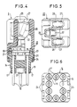
- the individual terminal block 1 presented in FIGS. 2 to 6 is designed to be plugged into a conventional multipoint connector 4 capable in particular of being mounted on a card or a flat support 13, such as a connector of the JR4 type. of the company ENTRELEC.
- the block 1 comprises for this purpose connection plugs, not visible in FIG. 2, which are inserted into individual connection pieces contained in the multipoint connector and accessible separately through orifices 12.
- the connector connection pieces multipoint 4 are connected to the conductive tracks of the support 13, in a manner known per se, via connection pins, not shown.
- These connection pieces can also be shaped so as to come into contact with the conductive tracks of a circuit board which is not shown, which is plugged into the end shaped for this purpose of the multipoint connector, the latter then passing through the support. 13.
- connection conductors and a braid grounding wire of the compensation cable 5 for thermoelectric torque are connected to the top of the individual terminal block 1.
- Figures 2 to 6 show an exemplary embodiment of such a block which is composed of a base 14 of a molded insulating material provided at its upper part with a microcircuit support location 15. Conduits made through the base allow the passage of connection plugs 16 intended to be plugged into connection pieces corresponding female of the multipoint connector 4. These connection plugs 16 are housed in insulating columns 17 of the base which position the latter precisely on the multipoint connector. At least some of the columns 17 are provided with annular bulges 18 allowing mechanical locking of the base on a connector by cooperation of these bulges 18 with corresponding annular grooves of the multipoint connector.
- a profile 19 of the base is intended to cooperate with one of the complementary forms with which the multipoint connector is provided to ensure a polarization preventing any mounting of the individual terminal block in a position not provided for it on the connector.
- connection plugs 16 are conventionally immobilized in the base 14 which is, for example, molded onto them, they are plugged into the connection holes of the microcircuit 19 making it possible to interconnect the latter with the measurement chain 3.
- connection rods 20 Three connection rods 20 - only two of which are visible in FIGS. 2 and 4-, allow the microcircuit 19 to be connected through which they are inserted, with the connection conductors and with the braid grounding wire. a compensation cable 5.
- connection rods 20 are pressed against the internal wall of three electrical connection terminals 21, of the axial connection type, in which the braid earthing wire and the connection conductors of the compensation cable are immobilized individually.
- An example of this type of terminal is described in particular in French patent 2,520,561 of the applicant.
- terminals are immobilized in a cover 22 of insulating material which covers the base 14 above the microcircuit 19.
- the cover here has tabs 24 provided which snap elastically by recesses 23 on pawls 25 formed laterally at the edge of the 'base.
- connection terminals 21 have their wire introduction inputs 26 which open at the upper part of the cover 22 of the individual junction block 1 assembled.
- insertion inlets 27 for the screwdriver blade are provided in the vicinity of the mouths for introducing wires into the cover 22 to give access to the heads of the operating screws, such as 28, of the connection terminals 21.
- the volume formed around the microcircuit 19 inside the base 14 and the cover 22 forms a closed enclosure for thermal regulation.
- the resistor 8 serving as a temperature probe inside the individual junction block 1 is fixed by gluing on one of the connection rods 20 instead of being on the microcircuit 19 which allows better take into account the outside temperature and the thermal mass represented by the connected wires.
- terminal blocks can be carried out directly on connectors on the level of the cards carrying the associated logic measurement circuits and this by simple plugging in, each block being for example identified in connection with the thermoelectric torque that it serves, for example, by standardized colored labeling corresponding to the nature of the conductors of said pair.
Landscapes
- Physics & Mathematics (AREA)
- General Physics & Mathematics (AREA)
- Multi-Conductor Connections (AREA)
- Manufacturing Of Electrical Connectors (AREA)
- Coupling Device And Connection With Printed Circuit (AREA)
- Connections Arranged To Contact A Plurality Of Conductors (AREA)
Applications Claiming Priority (1)
| Application Number | Priority Date | Filing Date | Title |
|---|---|---|---|
| FR8807790A FR2632777B1 (fr) | 1988-06-10 | 1988-06-10 | Bloc individuel de jonction pour la compensation de soudure froide d'un couple thermoelectrique |
Publications (2)
| Publication Number | Publication Date |
|---|---|
| EP0412197A1 true EP0412197A1 (de) | 1991-02-13 |
| EP0412197B1 EP0412197B1 (de) | 1994-09-21 |
Family
ID=9367179
Family Applications (1)
| Application Number | Title | Priority Date | Filing Date |
|---|---|---|---|
| EP19890114888 Expired - Lifetime EP0412197B1 (de) | 1988-06-10 | 1989-08-11 | Individueller Verbindungsblock zur Kompensation der kalten Lötstelle eines Thermoelementes |
Country Status (4)
| Country | Link |
|---|---|
| EP (1) | EP0412197B1 (de) |
| DE (1) | DE68918443T2 (de) |
| ES (1) | ES2061833T3 (de) |
| FR (1) | FR2632777B1 (de) |
Cited By (2)
| Publication number | Priority date | Publication date | Assignee | Title |
|---|---|---|---|---|
| CN106537105A (zh) * | 2014-08-12 | 2017-03-22 | 奥托尼克斯有限公司 | 用于热电偶温度补偿的端子板 |
| CN113340449A (zh) * | 2021-07-22 | 2021-09-03 | 湖北剑威电气科技有限公司 | 一种插接式温度传感器 |
Families Citing this family (1)
| Publication number | Priority date | Publication date | Assignee | Title |
|---|---|---|---|---|
| FR2632777B1 (fr) * | 1988-06-10 | 1992-01-10 | Alsthom Cgee | Bloc individuel de jonction pour la compensation de soudure froide d'un couple thermoelectrique |
Citations (6)
| Publication number | Priority date | Publication date | Assignee | Title |
|---|---|---|---|---|
| US1745149A (en) * | 1927-11-02 | 1930-01-28 | Bristol Company | Compensating apparatus for thermoelectric couples |
| US3911745A (en) * | 1974-12-13 | 1975-10-14 | Honeywell Inc | Resistance reference junction compensator |
| EP0115214A2 (de) * | 1982-12-27 | 1984-08-08 | Omron Tateisi Electronics Co. | Temperaturregler |
| US4483632A (en) * | 1982-07-15 | 1984-11-20 | Owens-Corning Fiberglas Corporation | Isothermal panel assembly for terminating a plurality of thermocouple leads |
| US4623266A (en) * | 1985-09-24 | 1986-11-18 | Rosemount Inc. | Cold junction compensation for thermocouple |
| FR2632777A1 (fr) * | 1988-06-10 | 1989-12-15 | Alsthom Cgee | Bloc individuel de jonction pour la compensation de soudure froide d'un couple thermoelectrique |
Family Cites Families (1)
| Publication number | Priority date | Publication date | Assignee | Title |
|---|---|---|---|---|
| JPS62200236A (ja) * | 1986-02-28 | 1987-09-03 | Chino Corp | 基準点補償装置 |
-
1988
- 1988-06-10 FR FR8807790A patent/FR2632777B1/fr not_active Expired - Fee Related
-
1989
- 1989-08-11 EP EP19890114888 patent/EP0412197B1/de not_active Expired - Lifetime
- 1989-08-11 ES ES89114888T patent/ES2061833T3/es not_active Expired - Lifetime
- 1989-08-11 DE DE1989618443 patent/DE68918443T2/de not_active Expired - Fee Related
Patent Citations (6)
| Publication number | Priority date | Publication date | Assignee | Title |
|---|---|---|---|---|
| US1745149A (en) * | 1927-11-02 | 1930-01-28 | Bristol Company | Compensating apparatus for thermoelectric couples |
| US3911745A (en) * | 1974-12-13 | 1975-10-14 | Honeywell Inc | Resistance reference junction compensator |
| US4483632A (en) * | 1982-07-15 | 1984-11-20 | Owens-Corning Fiberglas Corporation | Isothermal panel assembly for terminating a plurality of thermocouple leads |
| EP0115214A2 (de) * | 1982-12-27 | 1984-08-08 | Omron Tateisi Electronics Co. | Temperaturregler |
| US4623266A (en) * | 1985-09-24 | 1986-11-18 | Rosemount Inc. | Cold junction compensation for thermocouple |
| FR2632777A1 (fr) * | 1988-06-10 | 1989-12-15 | Alsthom Cgee | Bloc individuel de jonction pour la compensation de soudure froide d'un couple thermoelectrique |
Non-Patent Citations (1)
| Title |
|---|
| PATENT ABSTRACTS OF JAPAN, vol. 12, no. 53 (P-668)[2900], 18 février 1988; & JP-A-62 200 236 (CHINO CORP.) 03-09-1987 * |
Cited By (4)
| Publication number | Priority date | Publication date | Assignee | Title |
|---|---|---|---|---|
| CN106537105A (zh) * | 2014-08-12 | 2017-03-22 | 奥托尼克斯有限公司 | 用于热电偶温度补偿的端子板 |
| CN106537105B (zh) * | 2014-08-12 | 2019-05-10 | 奥托尼克斯有限公司 | 用于热电偶温度补偿的端子板 |
| CN113340449A (zh) * | 2021-07-22 | 2021-09-03 | 湖北剑威电气科技有限公司 | 一种插接式温度传感器 |
| CN113340449B (zh) * | 2021-07-22 | 2024-03-29 | 湖北剑威电气科技有限公司 | 一种插接式温度传感器 |
Also Published As
| Publication number | Publication date |
|---|---|
| FR2632777B1 (fr) | 1992-01-10 |
| ES2061833T3 (es) | 1994-12-16 |
| FR2632777A1 (fr) | 1989-12-15 |
| EP0412197B1 (de) | 1994-09-21 |
| DE68918443T2 (de) | 1995-01-19 |
| DE68918443D1 (de) | 1994-10-27 |
Similar Documents
| Publication | Publication Date | Title |
|---|---|---|
| US6072165A (en) | Thin film metal/metal oxide thermocouple | |
| FR2762908A1 (fr) | Procede et dispositif pour l'obtention d'un signal analogique compense a partir d'un signal de sortie d'un dispositif thermoelectrique | |
| FR2488406A1 (fr) | Procede et instrument de mesure de corrosion a compensation de temperature secondaire | |
| FR3075387B1 (fr) | Dispositif de mesure du courant electrique, appareil de mesure du courant et procede de fabrication d'un dispositif de mesure du courant | |
| WO2002048664A1 (en) | Transparent face temperature sensor and transparent face temperature controller | |
| EP0269485B1 (de) | Mehrschichtenstruktur zur Bildung einer Messvorrichtung bestehend aus einer Kombination eines Flussmessers und eines Temperaturfühlers sowie ein Verfahren zur Herstellung der Messvorrichtung und dieser Mehrschichtenstruktur | |
| EP0102262A1 (de) | Kryostatvorrichtung mit geringen Abmessungen für Photodetektoren | |
| KR101252909B1 (ko) | 가열 가능한 적외선 센서와 이 적외선 센서를 구비하는 적외선 온도계 | |
| US4483632A (en) | Isothermal panel assembly for terminating a plurality of thermocouple leads | |
| EP1792526B1 (de) | Mit integriertem wärmeverteiler ausgestattete elektronische einrichtung | |
| EP0412197B1 (de) | Individueller Verbindungsblock zur Kompensation der kalten Lötstelle eines Thermoelementes | |
| FR3027106A1 (fr) | Sonde de mesure de la temperature regnant en sortie de turbine d'helicoptere | |
| EP3056070A1 (de) | Elektrisches modul, elektrischen system mit derartigem elektrischen modul und zugehörige herstellungsverfahren | |
| EP0082768A2 (de) | Temperaturdetektor und Vorrichtung zu dessen Anwendung | |
| EP0557225A1 (de) | Kompensationsgerät für die kalte Lötstelle eines Thermoelements | |
| CA2915853C (fr) | Capteur differentiel de temperature | |
| FR2522823A1 (fr) | Cellule de mesure de la constante dielectrique de substances visqueuses ou pateuses | |
| FR2638522A1 (fr) | Systeme thermostatique pour regulation de temperature | |
| FR2812968A1 (fr) | Capteur micro-usine avec protection isolante des connexions | |
| FR2717901A1 (fr) | Dispositif de détection de courant. | |
| EP0067752B1 (de) | Thermische Kupplungszelle und mit solch einer Zelle ausgerüsteter temperaturgeregelter Raum | |
| EP0008275A1 (de) | Steckverbinder mit einer automatischen Regeleinrichtung zur Temperaturstabilisierung wenigstens eines Verbindungspunktes | |
| Jalink et al. | New photothermal cell equipped with Peltier elements for phase transition studies | |
| FR2461252A1 (fr) | Detecteur d'oxygene a electrolyte solide et procede de fabrication du detecteur | |
| FR2590982A1 (fr) | Dispositif de mesure d'un flux thermique |
Legal Events
| Date | Code | Title | Description |
|---|---|---|---|
| PUAI | Public reference made under article 153(3) epc to a published international application that has entered the european phase |
Free format text: ORIGINAL CODE: 0009012 |
|
| AK | Designated contracting states |
Kind code of ref document: A1 Designated state(s): BE DE ES FR GB GR IT LU NL |
|
| 17P | Request for examination filed |
Effective date: 19910813 |
|
| 17Q | First examination report despatched |
Effective date: 19930415 |
|
| GRAA | (expected) grant |
Free format text: ORIGINAL CODE: 0009210 |
|
| AK | Designated contracting states |
Kind code of ref document: B1 Designated state(s): BE DE ES FR GB GR IT LU NL |
|
| REF | Corresponds to: |
Ref document number: 68918443 Country of ref document: DE Date of ref document: 19941027 |
|
| GBT | Gb: translation of ep patent filed (gb section 77(6)(a)/1977) |
Effective date: 19941011 |
|
| ITF | It: translation for a ep patent filed | ||
| REG | Reference to a national code |
Ref country code: ES Ref legal event code: FG2A Ref document number: 2061833 Country of ref document: ES Kind code of ref document: T3 |
|
| REG | Reference to a national code |
Ref country code: GR Ref legal event code: FG4A Free format text: 3014438 |
|
| PGFP | Annual fee paid to national office [announced via postgrant information from national office to epo] |
Ref country code: ES Payment date: 19950510 Year of fee payment: 7 |
|
| PGFP | Annual fee paid to national office [announced via postgrant information from national office to epo] |
Ref country code: GR Payment date: 19950512 Year of fee payment: 7 |
|
| PGFP | Annual fee paid to national office [announced via postgrant information from national office to epo] |
Ref country code: FR Payment date: 19950529 Year of fee payment: 7 Ref country code: DE Payment date: 19950529 Year of fee payment: 7 |
|
| PGFP | Annual fee paid to national office [announced via postgrant information from national office to epo] |
Ref country code: BE Payment date: 19950602 Year of fee payment: 7 |
|
| PGFP | Annual fee paid to national office [announced via postgrant information from national office to epo] |
Ref country code: GB Payment date: 19950615 Year of fee payment: 7 |
|
| PGFP | Annual fee paid to national office [announced via postgrant information from national office to epo] |
Ref country code: LU Payment date: 19950701 Year of fee payment: 7 |
|
| PLBE | No opposition filed within time limit |
Free format text: ORIGINAL CODE: 0009261 |
|
| STAA | Information on the status of an ep patent application or granted ep patent |
Free format text: STATUS: NO OPPOSITION FILED WITHIN TIME LIMIT |
|
| PGFP | Annual fee paid to national office [announced via postgrant information from national office to epo] |
Ref country code: NL Payment date: 19950830 Year of fee payment: 7 |
|
| 26N | No opposition filed | ||
| PG25 | Lapsed in a contracting state [announced via postgrant information from national office to epo] |
Ref country code: LU Free format text: LAPSE BECAUSE OF NON-PAYMENT OF DUE FEES Effective date: 19960811 Ref country code: GB Effective date: 19960811 |
|
| PG25 | Lapsed in a contracting state [announced via postgrant information from national office to epo] |
Ref country code: ES Free format text: LAPSE BECAUSE OF THE APPLICANT RENOUNCES Effective date: 19960812 |
|
| PG25 | Lapsed in a contracting state [announced via postgrant information from national office to epo] |
Ref country code: BE Effective date: 19960831 |
|
| BERE | Be: lapsed |
Owner name: CEGELEC Effective date: 19960831 |
|
| PG25 | Lapsed in a contracting state [announced via postgrant information from national office to epo] |
Ref country code: GR Free format text: THE PATENT HAS BEEN ANNULLED BY A DECISION OF A NATIONAL AUTHORITY Effective date: 19970228 |
|
| PG25 | Lapsed in a contracting state [announced via postgrant information from national office to epo] |
Ref country code: NL Effective date: 19970301 |
|
| REG | Reference to a national code |
Ref country code: GR Ref legal event code: MM2A Free format text: 3014438 |
|
| GBPC | Gb: european patent ceased through non-payment of renewal fee |
Effective date: 19960811 |
|
| PG25 | Lapsed in a contracting state [announced via postgrant information from national office to epo] |
Ref country code: FR Effective date: 19970430 |
|
| NLV4 | Nl: lapsed or anulled due to non-payment of the annual fee |
Effective date: 19970301 |
|
| PG25 | Lapsed in a contracting state [announced via postgrant information from national office to epo] |
Ref country code: DE Effective date: 19970501 |
|
| REG | Reference to a national code |
Ref country code: FR Ref legal event code: ST |
|
| REG | Reference to a national code |
Ref country code: ES Ref legal event code: FD2A Effective date: 19991007 |
|
| PG25 | Lapsed in a contracting state [announced via postgrant information from national office to epo] |
Ref country code: IT Free format text: LAPSE BECAUSE OF NON-PAYMENT OF DUE FEES;WARNING: LAPSES OF ITALIAN PATENTS WITH EFFECTIVE DATE BEFORE 2007 MAY HAVE OCCURRED AT ANY TIME BEFORE 2007. THE CORRECT EFFECTIVE DATE MAY BE DIFFERENT FROM THE ONE RECORDED. Effective date: 20050811 |