EP0412255B1 - Dispositif de chauffage pour installation de fabrication de carton ondulé - Google Patents
Dispositif de chauffage pour installation de fabrication de carton ondulé Download PDFInfo
- Publication number
- EP0412255B1 EP0412255B1 EP90110532A EP90110532A EP0412255B1 EP 0412255 B1 EP0412255 B1 EP 0412255B1 EP 90110532 A EP90110532 A EP 90110532A EP 90110532 A EP90110532 A EP 90110532A EP 0412255 B1 EP0412255 B1 EP 0412255B1
- Authority
- EP
- European Patent Office
- Prior art keywords
- section according
- pressure
- conveyor belt
- corrugated cardboard
- pressure hood
- Prior art date
- Legal status (The legal status is an assumption and is not a legal conclusion. Google has not performed a legal analysis and makes no representation as to the accuracy of the status listed.)
- Expired - Lifetime
Links
- 238000010438 heat treatment Methods 0.000 title claims description 22
- 238000009434 installation Methods 0.000 claims 1
- 230000000694 effects Effects 0.000 description 4
- 239000000463 material Substances 0.000 description 4
- 238000005461 lubrication Methods 0.000 description 3
- 238000007789 sealing Methods 0.000 description 3
- XLYOFNOQVPJJNP-UHFFFAOYSA-N water Chemical compound O XLYOFNOQVPJJNP-UHFFFAOYSA-N 0.000 description 3
- 238000010521 absorption reaction Methods 0.000 description 2
- 239000003795 chemical substances by application Substances 0.000 description 2
- 238000001035 drying Methods 0.000 description 2
- 239000012528 membrane Substances 0.000 description 2
- 239000011324 bead Substances 0.000 description 1
- 239000003292 glue Substances 0.000 description 1
- 239000002184 metal Substances 0.000 description 1
- 238000003825 pressing Methods 0.000 description 1
- 230000003068 static effect Effects 0.000 description 1
- 230000032258 transport Effects 0.000 description 1
Images

Classifications
-
- B—PERFORMING OPERATIONS; TRANSPORTING
- B31—MAKING ARTICLES OF PAPER, CARDBOARD OR MATERIAL WORKED IN A MANNER ANALOGOUS TO PAPER; WORKING PAPER, CARDBOARD OR MATERIAL WORKED IN A MANNER ANALOGOUS TO PAPER
- B31F—MECHANICAL WORKING OR DEFORMATION OF PAPER, CARDBOARD OR MATERIAL WORKED IN A MANNER ANALOGOUS TO PAPER
- B31F1/00—Mechanical deformation without removing material, e.g. in combination with laminating
- B31F1/20—Corrugating; Corrugating combined with laminating to other layers
- B31F1/24—Making webs in which the channel of each corrugation is transverse to the web feed
- B31F1/26—Making webs in which the channel of each corrugation is transverse to the web feed by interengaging toothed cylinders cylinder constructions
- B31F1/28—Making webs in which the channel of each corrugation is transverse to the web feed by interengaging toothed cylinders cylinder constructions combined with uniting the corrugated webs to flat webs ; Making double-faced corrugated cardboard
- B31F1/2845—Details, e.g. provisions for drying, moistening, pressing
- B31F1/2877—Pressing means for bringing facer sheet and corrugated webs into contact or keeping them in contact, e.g. rolls, belts
- B31F1/2881—Pressing means for bringing facer sheet and corrugated webs into contact or keeping them in contact, e.g. rolls, belts for bringing a second facer sheet into contact with an already single faced corrugated web
Definitions
- the invention relates to a heating section for a corrugated cardboard system with the features of the preamble of claim 1.
- Such a heating section for a corrugated cardboard system is known from DE-OS 34 10 829.
- the disadvantage here is that the air is pressed through the conveyor belt and a kind of air lubrication occurs between the conveyor belt and the corrugated cardboard to be conveyed. This reduces the conveying effect of the conveyor belt.
- the air pressed into the conveyor belt prevents the absorption of water vapor, which is emitted by the heated corrugated cardboard.
- the invention has for its object to improve a heating section for a corrugated cardboard system so that the conveying effect of the conveyor belt and the absorption capacity for water vapor emerging from the corrugated cardboard is maintained.
- a wear-free seal between the underside of the pressure hood and the top of the conveyor belt should be achieved with little or no leakage.
- this separating means is formed by an air-impermeable endless belt moved with the conveyor belt or the corrugated cardboard, no relative movement occurs between the conveyor belt and the separating means. There is a reduction in wear.
- the lower edges of the pressure hood are bent inwards, a good and low-wear sealing against the separating agent is achieved.
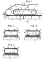
- the heating section 1 of a corrugated cardboard system has a plurality of heating plates 2, one behind the other. Its flat surface forms a heating surface 3 for the conveyed in the direction of arrow I, e.g. single corrugated cardboard 4.
- the heating plates 2 can extend in the transverse direction to the corrugated cardboard 4 over the maximum width. However, they can also be divided and controlled to different temperatures in the transverse direction.
- a one-sided corrugated cardboard 5 coming from a single-sided corrugated cardboard machine is fed to the heating section 1.
- the crests of the corrugations of the one-sided corrugated cardboard 5 are provided with glue.
- a smooth cover sheet 6 is fed to the underside. By applying pressure, the cover sheet 6 is glued to the one-sided corrugated cardboard 5 and dried by the heating section 1.
- an endless conveyor belt 8 which runs over deflection or drive rollers 9.
- the lower run 10 runs in a plane parallel to the heating surface 3 and at such a distance that it bears against the upper cover sheet 11 and takes the corrugated cardboard 7 with it through a corresponding friction effect.
- a pressure hood 12 is provided to increase the friction effect and the heat transfer from the heating surface 3 to the corrugated cardboard 4.
- This pressure hood 12 has a housing 13 which, as can be seen in FIG. 2, is rectangular in cross section.
- the top 14 is flat. It runs parallel to the heating surface 3.
- the adjoining side surfaces 15 have edges 16 and 17 which are bent inwards.
- the front and back also have inwardly curved edges, not shown.
- the housing 13 is arranged fixed in space, not shown. It can be raised and lowered for additional and setting purposes, optionally controlled.
- the ends of the housing 13 can have semicircular surfaces 18, 19. These surfaces can also be formed by tubes 20, 21, with which the side surfaces 15 are firmly connected.
- rollers can also be provided which are freely rotatably mounted or driven.
- An endless belt 25 runs over the surfaces 18, 19 and the top 14 of the housing 13.
- This can consist of air-impermeable material. It is flexible and preferably elastic. For example, a thin plastic or metal band can be used for this band.
- the lower strand 26 of the circulating belt 25 is pressed with its underside against the upper side of the lower strand 26 of the conveyor belt 8 by the excess pressure prevailing in the interior 27 of the housing 13, which is generated, for example, by a pump (not shown).
- the inwardly bent edges 16, 17 seal against the top of the endless belt 25.
- the distance between the edges 16, 17 is smaller than the width of the endless belt 25.
- the width of this endless belt 25 is equal to or smaller than the width of the conveyor belt 8, which extends in one piece over the maximum width of the heating surface 3. It consists of an air- and vapor-permeable material, so that the vapors produced by the heating through the heating surface 3, emitted by the corrugated cardboard 4 upwards, can be absorbed by this conveyor belt or can escape through it.
- the lower run 26 of the endless belt 25 ensures that air can escape from the housing 13 of the pressure hood 12 only as a leak via the sealing connection with the inwardly bent edges 16, 37. As far as possible, no air should flow through the endless belt 12. Air lubrication of the conveyor belt 8 is thus avoided.
- the endless belt 25 has transverse ribs 25 'on its outside, that is to say at the lower run 26 towards the top of the corrugated cardboard 4, preferably in a herringbone pattern. This makes it possible for the vapors emerging upwards from the conveyor belt 8 to evaporate laterally via the channels which run between the profiles 25 'and run transversely to the corrugated cardboard web.
- a small gap can be provided between the upper side of the lower run 26 of the endless belt 25 and the edges 16, 17 of the housing 13. This avoids the friction between the endless belt 25 and the housing 13. The leakage occurring is so low that the pressure in the interior can be easily maintained.
- the gap size can also be used to regulate the pressure in the pressure hood. In addition, this makes it possible to exchange air in the pressure hood, thus allowing hot air to escape from it.
- the edges 16, 17 are then pulled further inwards. These ends are perforated with holes 28, via which internal air from the interior 27 presses against the top of the endless belt 25.
- the underside of the housing 13 can be provided with a bottom 29 as a closed surface. This has a multiplicity of holes 28.
- pressure hoods 12 are present in the running direction of the single-wall corrugated cardboard 4 at a distance from one another.
- a single endless belt 25 is assigned to these printing hoods 12.
- This floor 29 can be made of a material which, in cooperation with the conveyor belt 8, causes little friction.
- the bottom 29 can also be connected to the pressure housing 13 such that it can move in height, for example via membrane beads or the like. It would also be possible to use this base 29 in the manner of a height-movable piston in the pressure housing 12.
Landscapes
- Engineering & Computer Science (AREA)
- Mechanical Engineering (AREA)
- Machines For Manufacturing Corrugated Board In Mechanical Paper-Making Processes (AREA)
- Drying Of Solid Materials (AREA)
Claims (16)
- Dispositif de chauffage pour machine de fabrication de carton ondulé équipé de plaques chauffantes sur la trajectoire suivie par le carton ondulé, d'une bande de convoyage sans fin dont le brin inférieur presse contre la surface supérieure du carton ondulé, d'un caisson de pression qui est placé au-dessus du brin inférieur de la bande de convoyage et dont la pression agit sur la face supérieure de celle-ci, dispositif caractérisé en ce qu'il comprend un séparateur (25) imperméable à l'air et apte à transmettre une pression qui est disposée entre la face supérieure de la bande de convoyage (8) et le caisson (12).
- Dispositif selon la revendication 1, caractérisé en ce que le séparateur (25) est constitué d'un tapis sans fin mobile imperméable à l'air.
- Dispositif selon la revendication 2, caractérisé en ce que le tapis sans fin (25) est guidé par des renvois (18, 19) constitués par des tubes ou des cylindres.
- Dispositif selon la revendication 3, caractérisé en ce que les cylindres de renvoi sont immobiles, tournants ou commandés.
- Dispositif selon la revendication 4, caractérisé en ce que les axes des renvois (18, 19), notamment des cylindres sont coplanaires et à une distance de la bande (8) telle que le tapis sans fin (25) porte sur le brin inférieur (26) de la bande (8) et clôt la partie inférieure du corps (13) du caisson (12) d'une manière étanche ou avec un petit interstice.
- Dispositif selon la revendication 1, caractérisé en ce que les bords (16, 17) inférieurs du caisson (12) sont repliés vers l'intérieur.
- Dispositif selon la revendication 6, caractérisé en ce que les bords (16, 17) sont pourvus d'orifices (28).
- Dispositif selon la revendication 1, caractérisé en ce que la partie inférieure du caisson (12) est munie d'une paroi (29) plane perforée d'orifices (28).
- Dispositif selon la revendication 1, caractérisé en ce que le séparateur (25) est constitué d'une plaque mince obturante mobile verticalement relativement au corps (13) du caisson (12).
- Dispositif selon l'une quelconque ou plusieurs des revendications précédentes, caractérisé en ce que le tapis sans fin (25) est muni de nervures (25') transversales sur sa face extérieure.
- Dispositif selon l'une quelconque ou plusieurs des revendications précédentes, caractérisé en ce que plusieurs caissons (12) sont disposés longitudinalement et/ou transversalement et sont entourés par un tapis sans fin (25)imperméable à l'air.
- Dispositif selon la revendication 11, caractérisé en ce que les caissons (12) sont espacés et sont logés au-dessus et entre le tapis (25) et la bande (8).
- Dispositif selon la revendication 1, caractérisé en ce que la largeur du séparateur (25) est égale ou inférieure à celle des plaques chauffantes (3).
- Dispositif selon la revendication 2, caractérisé en ce que un ou plusieurs tapis sans fin (25) sont utilisés.
- Dispositif selon la revendication 1, caractérisé en ce que le caisson (12) est monté mobile verticalement.
- Dispositif selon la revendication 15, caractérisé en ce que la hauteur du caisson (12) est commandée, notamment en fonction du déplacement du carton ondulé, de la pression dans le caisson, ou de moyens pareils.
Applications Claiming Priority (2)
| Application Number | Priority Date | Filing Date | Title |
|---|---|---|---|
| DE3926483 | 1989-08-10 | ||
| DE3926483A DE3926483C1 (fr) | 1989-08-10 | 1989-08-10 |
Publications (2)
| Publication Number | Publication Date |
|---|---|
| EP0412255A1 EP0412255A1 (fr) | 1991-02-13 |
| EP0412255B1 true EP0412255B1 (fr) | 1993-07-14 |
Family
ID=6386897
Family Applications (1)
| Application Number | Title | Priority Date | Filing Date |
|---|---|---|---|
| EP90110532A Expired - Lifetime EP0412255B1 (fr) | 1989-08-10 | 1990-06-02 | Dispositif de chauffage pour installation de fabrication de carton ondulé |
Country Status (2)
| Country | Link |
|---|---|
| EP (1) | EP0412255B1 (fr) |
| DE (2) | DE3926483C1 (fr) |
Families Citing this family (9)
| Publication number | Priority date | Publication date | Assignee | Title |
|---|---|---|---|---|
| DE4212847A1 (de) * | 1992-04-16 | 1993-11-18 | Bhs Bayerische Berg | Heizvorrichtung für eine Wellpappenanlage |
| DE19536007A1 (de) * | 1995-09-28 | 1997-04-03 | Bhs Corr Masch & Anlagenbau | Maschine zur Herstellung einer mindestens einseitig kaschierten Wellpappebahn |
| DE19716716C2 (de) * | 1997-04-21 | 2002-04-18 | Bhs Corr Masch & Anlagenbau | Heizvorrichtung für eine Wellpappenanlage |
| DE19810841C2 (de) * | 1998-03-12 | 2002-03-14 | Bhs Corr Masch & Anlagenbau | Heizvorrichtung für eine Wellpappenanlage |
| DE19857370C2 (de) * | 1998-12-11 | 2002-01-24 | Bhs Corr Masch & Anlagenbau | Heizvorrichtung für eine Wellpappenanlage |
| DE19954754A1 (de) * | 1999-11-15 | 2001-05-17 | Bhs Corr Masch & Anlagenbau | Heizvorrichtung für eine Wellpappemaschine |
| GB0423068D0 (en) * | 2004-10-16 | 2004-11-17 | Simon Corrugating Machinery Lt | Heat transfer system |
| WO2010005279A1 (fr) * | 2008-07-07 | 2010-01-14 | Chee Meng Chan | Dispositif de soulèvement de courroie de production de carton ondulé |
| IT1402843B1 (it) * | 2010-12-06 | 2013-09-27 | Fosber Spa | "dispositivo per la produzione di cartone ondulato e relativo metodo" |
Family Cites Families (8)
| Publication number | Priority date | Publication date | Assignee | Title |
|---|---|---|---|---|
| US3140030A (en) * | 1962-04-26 | 1964-07-07 | Koppers Co Inc | Vacuum device for pulling a continuous web |
| GB1046813A (en) * | 1964-04-01 | 1966-10-26 | Niwa Machinery Co Ltd | Pressing and drying devices for corrugated board manufacturing equipment |
| DE1561493A1 (de) * | 1967-04-17 | 1970-03-05 | Koppers Co Inc | Vorrichtung fuer die Herstellung von Wellpappe |
| GB1179908A (en) * | 1967-05-31 | 1970-02-04 | Koppers Co Inc | Improvements in or relating to apparatus for use in the production of corrugated board. |
| DE2205568A1 (de) * | 1972-02-07 | 1973-08-16 | Eickhoff Universal Wellpappenm | Verfahren und vorrichtung zum belasten einer mit doppelseitiger glatter deckbahn ausgestatteten wellpappenbahn in der heiz- und/oder kuehlpartie einer wellpappenmaschine |
| DE2310613C3 (de) * | 1973-03-02 | 1976-01-08 | Bhs-Bayerische Berg-, Huetten- Und Salzwerke Ag, 8000 Muenchen | Vorrichtung zum Andrücken einer bewegten Materialbahn, insbesondere Wellpappenbahn, an eine stationäre, insbesondere als Heizpartie ausgebildete Abstützfläche |
| DE2648088A1 (de) * | 1976-10-23 | 1978-05-03 | Karl Schilf | Verfahren und vorrichtung zur kontinuierlichen herstellung von ein- bzw. mehrschichtigen flaechigen materialien |
| GB8308645D0 (en) * | 1983-03-29 | 1983-05-05 | Neu Eng Ltd | Corrugated board |
-
1989
- 1989-08-10 DE DE3926483A patent/DE3926483C1/de not_active Expired - Lifetime
-
1990
- 1990-06-02 EP EP90110532A patent/EP0412255B1/fr not_active Expired - Lifetime
- 1990-06-02 DE DE9090110532T patent/DE59001955D1/de not_active Expired - Fee Related
Also Published As
| Publication number | Publication date |
|---|---|
| DE3926483C1 (fr) | 1991-01-31 |
| DE59001955D1 (de) | 1993-08-19 |
| EP0412255A1 (fr) | 1991-02-13 |
Similar Documents
| Publication | Publication Date | Title |
|---|---|---|
| EP3150378B1 (fr) | Installation et procédé pour la production de carton ondulé | |
| DE69824739T2 (de) | Verfahren und gerät zur herstellung von wellpappe | |
| DE69726553T2 (de) | VAKUUM UNTERSTüTZTE BAHNANTRIEBSVORRICHTUNG FüR DOPPELSCHICHTIGE WELLPAPPE | |
| EP0180015A2 (fr) | Dispositif pour le séchage ou le refroidissement d'objets minces tels que des feuilles, plaques ou objets similaires | |
| DE69813441T2 (de) | Einseitige Wellpappenmaschine | |
| DE3926483C1 (fr) | ||
| DE2511873B2 (de) | Presse zur ausuebung einer flaechenpressung | |
| DE2209895A1 (de) | Verfahren und Vorrichtung zur kontinuierlichen Herstellung hohler Strangpreßlinge | |
| DE3118563A1 (de) | Maschine zum kontinuierlichen trocknen und/oder verbinden von furnieren | |
| DE69915150T2 (de) | Vorrichtung und Verfahren zur Herstellung einer einseitigen Wellpappe | |
| DE4018426C2 (fr) | ||
| DE2205568A1 (de) | Verfahren und vorrichtung zum belasten einer mit doppelseitiger glatter deckbahn ausgestatteten wellpappenbahn in der heiz- und/oder kuehlpartie einer wellpappenmaschine | |
| EP0941835B1 (fr) | Dispositif de chauffage pour un système de fabrication de carton ondulé | |
| DE3507667C2 (fr) | ||
| DE3036816A1 (de) | Verfahren zum zusammenfuehren einer endlosbahn mit kontinuierlich gefoerdertem flaechigem gut, sowie vorrichtung zur durchfuehrung des verfahrens | |
| DE1629038B1 (de) | Abdichtvorrichtung fuer einen Trockner | |
| DE19605296C1 (de) | Anlage für die Herstellung von Holzwerkstoffplatten | |
| DE2410214A1 (de) | Dichtung | |
| EP0165377B1 (fr) | Dispositif pour produire une sous-pression ou une surpression sur une voie transportant du papier dans le sens de la longueur, notamment dans une installation de carton ondulé | |
| DE2201742A1 (de) | Verfahren und vorrichtung zum trocknen und transportieren von einer aus beleimten pappebahnen zusammengesetzten wellpappenbahn | |
| DE19716716C2 (de) | Heizvorrichtung für eine Wellpappenanlage | |
| EP1068138A1 (fr) | Transporteur a courroie a surface profilee, ainsi que procede pour le raccord des deux extremites d'un tel transporteur a courroie | |
| EP0523264B1 (fr) | Dispositif pour la fabrication des cartons ondulés simple face | |
| DE19627720B4 (de) | Anlage für die Herstellung von Holzwerkstoffplatten | |
| DE4440997A1 (de) | Verfahren und Anlage zur kontinuierlichen Herstellung von Holzwerkstoffplatten |
Legal Events
| Date | Code | Title | Description |
|---|---|---|---|
| PUAI | Public reference made under article 153(3) epc to a published international application that has entered the european phase |
Free format text: ORIGINAL CODE: 0009012 |
|
| AK | Designated contracting states |
Kind code of ref document: A1 Designated state(s): DE FR GB IT |
|
| 17P | Request for examination filed |
Effective date: 19910315 |
|
| 17Q | First examination report despatched |
Effective date: 19920814 |
|
| GRAA | (expected) grant |
Free format text: ORIGINAL CODE: 0009210 |
|
| AK | Designated contracting states |
Kind code of ref document: B1 Designated state(s): DE FR GB IT |
|
| ITF | It: translation for a ep patent filed | ||
| REF | Corresponds to: |
Ref document number: 59001955 Country of ref document: DE Date of ref document: 19930819 |
|
| GBT | Gb: translation of ep patent filed (gb section 77(6)(a)/1977) |
Effective date: 19930818 |
|
| ET | Fr: translation filed | ||
| PLBE | No opposition filed within time limit |
Free format text: ORIGINAL CODE: 0009261 |
|
| STAA | Information on the status of an ep patent application or granted ep patent |
Free format text: STATUS: NO OPPOSITION FILED WITHIN TIME LIMIT |
|
| ITPR | It: changes in ownership of a european patent |
Owner name: CESSIONE;BHS CORRUGATED MASCHINEN - UND ANLAGENBAU |
|
| 26N | No opposition filed | ||
| REG | Reference to a national code |
Ref country code: FR Ref legal event code: TP Ref country code: FR Ref legal event code: CA |
|
| REG | Reference to a national code |
Ref country code: GB Ref legal event code: 732E |
|
| PGFP | Annual fee paid to national office [announced via postgrant information from national office to epo] |
Ref country code: FR Payment date: 19980520 Year of fee payment: 9 |
|
| PGFP | Annual fee paid to national office [announced via postgrant information from national office to epo] |
Ref country code: GB Payment date: 19980522 Year of fee payment: 9 |
|
| PGFP | Annual fee paid to national office [announced via postgrant information from national office to epo] |
Ref country code: DE Payment date: 19980824 Year of fee payment: 9 |
|
| PG25 | Lapsed in a contracting state [announced via postgrant information from national office to epo] |
Ref country code: GB Free format text: LAPSE BECAUSE OF NON-PAYMENT OF DUE FEES Effective date: 19990602 |
|
| PG25 | Lapsed in a contracting state [announced via postgrant information from national office to epo] |
Ref country code: FR Free format text: THE PATENT HAS BEEN ANNULLED BY A DECISION OF A NATIONAL AUTHORITY Effective date: 19990630 |
|
| GBPC | Gb: european patent ceased through non-payment of renewal fee |
Effective date: 19990602 |
|
| PG25 | Lapsed in a contracting state [announced via postgrant information from national office to epo] |
Ref country code: DE Free format text: LAPSE BECAUSE OF NON-PAYMENT OF DUE FEES Effective date: 20000503 |
|
| REG | Reference to a national code |
Ref country code: FR Ref legal event code: ST |
|
| PG25 | Lapsed in a contracting state [announced via postgrant information from national office to epo] |
Ref country code: IT Free format text: LAPSE BECAUSE OF NON-PAYMENT OF DUE FEES;WARNING: LAPSES OF ITALIAN PATENTS WITH EFFECTIVE DATE BEFORE 2007 MAY HAVE OCCURRED AT ANY TIME BEFORE 2007. THE CORRECT EFFECTIVE DATE MAY BE DIFFERENT FROM THE ONE RECORDED. Effective date: 20050602 |