EP0412647A2 - Schuhhalter für eine Maschine zum Formen des Schuhoberteils - Google Patents
Schuhhalter für eine Maschine zum Formen des Schuhoberteils Download PDFInfo
- Publication number
- EP0412647A2 EP0412647A2 EP90307310A EP90307310A EP0412647A2 EP 0412647 A2 EP0412647 A2 EP 0412647A2 EP 90307310 A EP90307310 A EP 90307310A EP 90307310 A EP90307310 A EP 90307310A EP 0412647 A2 EP0412647 A2 EP 0412647A2
- Authority
- EP
- European Patent Office
- Prior art keywords
- shoe
- insole
- support
- presser
- presser member
- Prior art date
- Legal status (The legal status is an assumption and is not a legal conclusion. Google has not performed a legal analysis and makes no representation as to the accuracy of the status listed.)
- Withdrawn
Links
Images


Classifications
-
- A—HUMAN NECESSITIES
- A43—FOOTWEAR
- A43D—MACHINES, TOOLS, EQUIPMENT OR METHODS FOR MANUFACTURING OR REPAIRING FOOTWEAR
- A43D23/00—Single parts for pulling-over or lasting machines
- A43D23/02—Wipers; Sole-pressers; Last-supports; Pincers
- A43D23/025—Last-supports
Definitions
- This invention is concerned with a shoe support for supporting a shoe, comprising an upper and an insole on a last, for a shoe upper conforming operation to be performed thereon.
- a shoe support for supporting a shoe, comprising an upper and an insole on a last, for a shoe upper conforming operation to be performed thereon, said support comprising a last pin and a toe rest for supporting respectively the heel and toe ends of a shoe to be operated upon, presser means cooperable with the toe rest for clamping the forepart portion of the insole of the shoe against the last bottom and for holding the toe end portion of the shoe against the toe rest, and gripper means by which the upper of the shoe thus held can be drawn heightwise about the last in a direction away from the last bottom and also lengthwise in a direction away from the heel end of the shoe thus to tension the upper about its last, wherein the gripper means comprises two grippers arranged at opposite sides of the shoe and mounted for movement in directions extending heightwise and lengthwise of the shoe, and the presser means comprises two presser members, one associated with each gripper, each presser member being mounted for movement between an operative position, in which it engages an insole
- each presser member is mounted for movement in a direction heightwise of the shoe upper on a support which is itself also mounted for movement in a direction heightwise of the shoe, and in addition the support supports the gripper associated with the presser member so that, upon heightwise movement of the support, the gripper is moved heightwise relative to the presser member.
- first power means is provided for effecting heightwise movement of the presser member to bring it into engagement with a shoe bottom and thereafter, through its mounting on the support, for effecting heightwise movement of the support and thus of the associated gripper.
- Each presser member thus constitutes a reaction lever against which the gripper can pull, the position of the applied reaction force being in this case adjacent the shoe upper tensioning force, so that there is no significant tendency for the position of the last in the shoe support to be disturbed.
- the gripper is mounted on said support for movement relative to the presser member in a direction lengthwise of the shoe, and second power means is provided for effecting such lengthwise movement of the gripper.
- the aforementioned shoe support would be useful for handling both fixed insoles, i.e. insoles previously attached to the last bottom albeit temporarily, and also loose insoles, i.e. insoles placed in position on the last bottom without being temporarily attached thereto.
- loose insoles would be positioned after the initial gripping of the upper, that is to say after the presser members have been moved to their operative positions, the shoe-engaging end portions of the presser members being flat for this purpose.
- At least the first presser member is conveniently constituted by a generally U-shaped portion, arranged with the open end of the U facing towards the shoe bottom in order to accommodate the upstanding lasting margin of the shoe upper without disturbing its position, and a generally flat shoe-engaging portion disposed at the free end of the presser member, beyond the generally U-shaped portion thereof.
- This generally flat portion enables loose insoles to overlie it when the first presser member is in its operative position, without significantly affecting the position of the insole on the last.
- a shoe under operator control a shoe can first be positioned in the shoe support and be held by the first presser member and then, prior to any shoe upper conforming operation, the loose insole can be located on the last bottom and be clamped firstly by the second presser member and thereafter by the first presser member also as aforesaid.
- the withdrawal of the first presser member after the second presser member has engaged the insole as aforesaid may take place upon a third operation of the operator-actuatable control means, but preferably the withdrawal of the first presser member and its subsequent return to its operative position take place in timed relation with one another and with the movement of the second presser member to its operative position as aforesaid in response to the second operation of the operator-actuatable control means.
- the shoe support 10 now to be described forms part of a machine for carrying out a combined operation of heel end assembling, backpart moulding and heel seat lasting of shoe uppers; such machines are utilised for enabling the heel seat of a shoe, comprising a loose upper U on a last and an insole I, which may be fixed or loose, positioned on the last bottom, to be lasted while at the same time a moulding operation is effected on the backpart of the shoe upper.
- a machine comprises two operating stations (only one of which is indicated in the drawings) arranged side-by-side for alternate operation by the machine operator.
- Such a machine is described e.g. in EP-A0240171 and details of the machine are incorporated herein by reference thereto.
- the two stations are identical in construction. In practice one station is set up for operating on right shoes, the other on lefts.
- Each station comprises a shoe support in accordance with the invention and generally designated 10 which is so arranged that a shoe is supported thereby with the plane of its heel seat at an angle of 35° to the vertical, away from the operator.
- the shoe support 10 which is generally similar, except as hereinafter described, to the support described in EP-A0240171 (on which reliance is thus placed for purposes of the present disclosure, in particular like parts being given the same reference numerals, such numerals being placed in brackets where such parts are not shown in the drawings of the present application), comprises a heel support generally designated (16), which comprises a so-called last pin (18) mounted on a column (20) which is movable in a direction heightwise of the heel seat of the shoe supported thereby, by means of a piston-and-cylinder arrangement (22) supported on a frame portion (24).
- a forwardly extending bracket (26) on which is carried a forwardly and rearwardly extending support slide 30 (Fig. 1) supporting, for sliding movement thereon, a casting 32 having an upstanding column portion 34.
- the casting 32 is movable fore-and-aft by means of a threaded rod 36 captive in the support slide and threadedly engaging the casting, said rod being provided at its forward end with a hand wheel 38.
- a clamping lever 40 is provided for securing the casting in its adjusted position against the support slide 30.
- At the upper end of the column portion 34 is a collar 42 having two pins 44 projecting therefrom diametrically opposite one another.
- a height-setting member 46 comprising a sleeve the side wall of which is provided with a stepped row of recesses 48 engagable with the pins 44. By selecting an appropriate recess 48, the height of the member 46 can thus be adjusted.
- Carried within the column portion 34 is a support rod 50 having at its upper end a threaded portion on which a knurled nut 52 is secured, said nut resting on the top of the member 46.
- a block mounted at the upper end of the support rod 50 is a block (not shown) in which is provided a guideway for a slide 54 on which a support housing 56 is carried.
- an adjustment bolt 58 is provided, captive in the housing and threaded into a portion of the block.
- the upper end of the support rod 50 is tubular and receives therein a further rod 60 on which a toe pad 62 is carried.
- the rod 60 is threaded and carries a knurled adjusting nut 64 which rests on the upper end of the support rod 50.
- the support housing 56 is generally in the shape of an inverted U and supports, at each side thereof, a shoe upper gripping and tensioning assembly generally designated 66. These assemblies are mirror-opposites of one another, and consequently only one such assembly will now be described. Referring to the left hand side Figure 1 (in which part of the assembly has been broken away to show details now to be described), supported by pivots 74 on two spaced lugs 68 of the support housing 56 are two levers 70 on which in turn a support plate 72 is carried, the two levers 70 together with the plate 72 and the support housing 56 itself constituting a four-bar linkage arrangement by which the plate 72 can be moved up-and-down substantially parallel to a line connecting the pivots 74, and the movement of the plate, in moving up-and-down, will include only a small component of in-and-out movement.
- the support plate 72 provides at its upper end a pivot 76 for a presser member, or so-called reaction lever, 78, the pivot and lever being so dimensioned and arranged that an inner end 80 of the lever will engage with the bottom of the shoe supported in the shoe support when said end 80 is pivoted downwardly theretowards.
- the reaction lever 78 is shaped so as to provide a portion having a shape generally of an inverted U, whereby the lever can accommodate an upstanding lasting margin of the shoe upper, while the free end 80 of said lever, beyond the U-shaped portion, is flat and relatively narrow, for purposes to be referred to hereinafter.
- a piston-and-cylinder arrangement 82 is provided mounted on the support plate 72.
- the upper one of the levers 70 is connected to the support plate by a pin-and-slot connection 84, a clamp arrangement 86 being provided for clamping the lever and plate in adjusted position.
- the clamp arrangement is released, the plate can pivot about the lower of the two pivots 74.
- the shoe upper gripping and tensioning assembly 66 also comprises a gripper assembly generally designated 88.
- the gripper assembly comprises a fixed jaw 90 and a movable jaw 92 pivotal relative to the fixed jaw under the action of a piston-and-cylinder arrangement 94.
- the gripper assembly 88 is mounted for sliding movement, with a frictional fit, in a guideway (96) for movement towards and away from the shoe, said guideway being provided in a block (98) which is itself support for pivotal movement on a support plate 100.
- the block (98) has a slot (102) formed therein and receiving a clamping screw (104) by which the block, and thus the gripper assembly 88, can be clamped in adjusted position on the plate 100.
- This plate is formed integral with a support 106 which is mounted for sliding heightwise adjusting movement on a support column 108.
- a pin-and-slot guide 110 is provided, and a clamp arrangement 112 secures the support 106 in heightwise adjusted position.
- the position of the gripper assembly 88 heightwise of the shoe bottom can thus be adjusted.
- the support column 108 is supported at its lower end on a pivot 114 carried by the support plate 72, the axis of the pivot extending in a direction widthwise of the shoe whereby the gripper assembly 88 can move in a direction fore-and-aft of the shoe.
- a piston-and-cylinder arrangement 116 is provided, mounted on the support plate 72 and connected via a bell crank lever 118 and a link 120 to the support column 108.
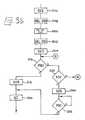
- the control of the sequence of operations of the machine, including the shoe support 10, is effected by microprocessor or other electronic means, being initiated by operator-actuatable control means including a foot treadle (not shown, but labelled FS1 in Figure 3).
- operator-actuatable control means including a foot treadle (not shown, but labelled FS1 in Figure 3).
- step 202 the status of a further switch SS1 is interrogated, this switch representing a selection between a "loose insole” sequence and a "fixed insole” sequence. Where the latter sequence is selected, i.e. when a "No" answer is detected at step 202, relay RL1 and solenoids SV1, SV2, SV3 are all actuated (steps 204, 206, 208 and 210).
- Relay RL1 is effective merely to supply power to the solenoids, while solenoid SV1 powers piston-and-cylinder arrangements 94, whereby the gripper assemblies 88 are actuated, and solenoids SV2 and SV3 supply low power to piston-and-cylinder arrangements 82, whereby the reaction levers 78 are caused to pivot about their pivot 76 to bring the shoe-engaging end portions 80 thereof into engagement with the shoe bottom and to apply an initial tension to the upper by the gripper assemblies 88.
- step 212 Thereafter a short delay takes place (step 212) for a period of 100 milliseconds, whereafter solenoid SV4 is energised (step 214) supplying low power to piston-and-cylinder arrangements 116, which are thus actuated to cause the support columns 108 to be pivoted about the pivots 114 thus to move the gripper assemblies 88 in a direction away from the heel end of the shoe, and thus to cause the shoe upper to be tensioned lengthwise of the last. At this stage therefore the backpart of the upper is lightly tensioned about the heel end portion of the last.
- the operator-actuatable control means comprises, in addition to the foot treadle FS1, a manually operable switch (not shown, but labelled PB1 in Figure 3).
- PB1 manually operable switch
- the status of this switch PB1 is interrogated (step 216). If a "Yes" answer is received, indicating that the switch is operated, then solenoid SV5 is energised (step 218), whereby high pressure is applied to the piston-and- cylinder arrangements 82 and 116, whereby the shoe upper is tensioned both lengthwise and heightwise of the shoe last under high pressure, and at the same time a guard arrangement (not shown) is lowered (step 220) thus to protect the operating locality from access by the operator.
- the cycle of operation of the machine is then continued as specifically described in e.g. EP-A 0335566.
- step 222 If an answer "No” is obtained at step 216, then the status of the foot switch FS1 is interrogated (step 222); if "No” is detected, then the system loops via junction B until either the hand-operated switch PB1 or the foot treadle FS1 is actuated. If "Yes” is obtained at step 222, then solenoid SV5 is energised (step 224) to cause the upper to be tensioned under high pressure as aforesaid and thereafter the status of the hand-operated switch PB1 is interrogated (step 226), the system looping until a "Yes" answer is provided, whereafter the guard arrangement is closed at step 220, and the machine cycle continues as aforesaid.
- the switch PB1 requires a two-hand operation.
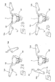
- step 202 if a "Yes" answer is obtained, indicating that a "loose insole” sequence has been selected, then firstly solenoids SV1 and SV2 are energised (respectively steps 228, 230), whereby the gripper assemblies 88 are actuated and close on the upstanding lasting margin of the shoe upper and also a first reaction lever 78A is caused to pivot about its pivot 76 to bring its shoe-engaging end portion80 into contact with the last bottom (see Figure 2A). It has been found preferable that the reaction lever which engages the "outside" of the shoe bottom is the lever which is first operated as aforesaid.
- step 244 the status of the foot switch FS1 is then further interrogated (step 244); if a "Yes” answer is obtained, indicating that the switch has not been released, then the system merely loops until the switch is in fact released. A "No” answer indicates that the switch has in fact been released, whereupon the following sequence then occurs: solenoid SV3 is energised (step 246), thus to bring the other reaction lever 78B into engagement with the shoe bottom and clamp the insole against the last bottom, again under low pressure (see Figure 2B).
- a time delay of 250 milliseconds is then effected (step 248) followed by the de-energising of solenoid SV2 (step 250) whereby the first reaction lever 78A is pivoted once more about its pivot 76 and withdrawn from beneath the insole in engagement with the last bottom, the second reaction lever 78B having taken over the control of the shoe from the first reaction lever (see Figure 2C).
- the release (second actuation) of the foot switch FS1 at step 244 is effective only to move the second reaction lever 78B into its operative position, the subsequent withdrawal of the first reaction lever 78A then taking place only upon a third actuation of said switch FS1.
- step 252 A further time delay of 250 milliseconds then takes place (step 252) and then solenoid SV2 is re-energised (step 254), and the first reaction lever is thus returned into engagement with the insole ( Figure 2D). Thereafter the programme moves to step 216 and the cycle of operation of the machine continues as described above.
- a "machine release” switch (not shown) may be actuated by the operator, which is effective to return all the moving parts of the machine, including the shoe support 10, to their rest position.
- the status of the "machine release” switch is monitored at regular and frequent intervals by way of an interrupt to the main programme.
- the operator may selectively work with fixed insoles or loose insoles in the manner described above, so that a more versitile machine is produced which is more compatible with a variety of factory operating systems than has previously been the case, without detriment to the reliability of the machine or the acceptability of the finished shoes.
Landscapes
- Footwear And Its Accessory, Manufacturing Method And Apparatuses (AREA)
Applications Claiming Priority (2)
| Application Number | Priority Date | Filing Date | Title |
|---|---|---|---|
| GB8918036 | 1989-08-07 | ||
| GB898918036A GB8918036D0 (en) | 1989-08-07 | 1989-08-07 | Shoe support for shoe upper conforming machine |
Publications (2)
| Publication Number | Publication Date |
|---|---|
| EP0412647A2 true EP0412647A2 (de) | 1991-02-13 |
| EP0412647A3 EP0412647A3 (en) | 1992-11-19 |
Family
ID=10661289
Family Applications (1)
| Application Number | Title | Priority Date | Filing Date |
|---|---|---|---|
| EP19900307310 Withdrawn EP0412647A3 (en) | 1989-08-07 | 1990-07-04 | Shoe support for shoe upper conforming machine |
Country Status (3)
| Country | Link |
|---|---|
| EP (1) | EP0412647A3 (de) |
| GB (1) | GB8918036D0 (de) |
| ZA (1) | ZA905642B (de) |
Cited By (1)
| Publication number | Priority date | Publication date | Assignee | Title |
|---|---|---|---|---|
| CN115989916A (zh) * | 2023-03-10 | 2023-04-21 | 江苏伊贝实业股份有限公司 | 一种鞋底压合滚边装置 |
Family Cites Families (3)
| Publication number | Priority date | Publication date | Assignee | Title |
|---|---|---|---|---|
| US2072214A (en) * | 1935-04-05 | 1937-03-02 | Arthur Frederick Pym | Method and means for use in lasting shoes |
| GB8605766D0 (en) * | 1986-03-08 | 1986-04-16 | Busm Co Ltd | Shoe support |
| DE3714919A1 (de) * | 1987-05-05 | 1988-11-24 | Schoen & Cie Gmbh | Leistenausricht- und haltevorrichtung an einer fersenzwickmaschine |
-
1989
- 1989-08-07 GB GB898918036A patent/GB8918036D0/en active Pending
-
1990
- 1990-07-04 EP EP19900307310 patent/EP0412647A3/en not_active Withdrawn
- 1990-07-18 ZA ZA905642A patent/ZA905642B/xx unknown
Cited By (1)
| Publication number | Priority date | Publication date | Assignee | Title |
|---|---|---|---|---|
| CN115989916A (zh) * | 2023-03-10 | 2023-04-21 | 江苏伊贝实业股份有限公司 | 一种鞋底压合滚边装置 |
Also Published As
| Publication number | Publication date |
|---|---|
| GB8918036D0 (en) | 1989-09-20 |
| EP0412647A3 (en) | 1992-11-19 |
| ZA905642B (en) | 1992-02-26 |
Similar Documents
| Publication | Publication Date | Title |
|---|---|---|
| EP0412647A2 (de) | Schuhhalter für eine Maschine zum Formen des Schuhoberteils | |
| EP0100636B1 (de) | Zwickmaschine für den Zehenbereich mit einstellbarer Fersenhalterung | |
| US1142557A (en) | Machine for use in the manufacture of boots and shoes. | |
| US4389745A (en) | Molding an insole and attaching the molded insole to a last bottom | |
| US1365222A (en) | Work-support | |
| US4400839A (en) | Machine for lasting heel seat portions of shoes | |
| US2754529A (en) | Breast line lasting machines | |
| US4407033A (en) | Combination toe and side lasting machine | |
| US4744120A (en) | Shoe support for shoe upper conforming machine | |
| US4404700A (en) | Machine for lasting side portions of shoes | |
| EP0093608B1 (de) | Werkstück-Transporteinrichtung | |
| US3668728A (en) | Machine for disassembling a shoe from a last | |
| US3075209A (en) | Machines for attaching loose outsoles to the breasts of loose louis heels | |
| US2422737A (en) | Method of and machine for turning the platform covers of platform shoes | |
| EP0335566B1 (de) | Fersenform- und -zwickmaschine | |
| US3594838A (en) | Lasting machines | |
| EP0247831B1 (de) | Seiten- und Fersenzwickmaschine | |
| US4593423A (en) | Lasting heel seat and side portions of a shoe | |
| WO1989008412A1 (en) | Pulling over and toe lasting machine | |
| US1085400A (en) | Holddown. | |
| US2608701A (en) | Platform laying and platform cover turning machine | |
| US2704849A (en) | Apparatus for use in the manufacture of shoes | |
| US4392266A (en) | Molded shanks | |
| EP0118243B1 (de) | Schuhzwicken unter Anwendung eines Klebemittels | |
| EP0071394A2 (de) | Maschine zum Auftragen eines Klebstoffstreifens auf den Boden eines Leistens |
Legal Events
| Date | Code | Title | Description |
|---|---|---|---|
| PUAI | Public reference made under article 153(3) epc to a published international application that has entered the european phase |
Free format text: ORIGINAL CODE: 0009012 |
|
| AK | Designated contracting states |
Kind code of ref document: A2 Designated state(s): FR GB IT |
|
| PUAL | Search report despatched |
Free format text: ORIGINAL CODE: 0009013 |
|
| AK | Designated contracting states |
Kind code of ref document: A3 Designated state(s): FR GB IT |
|
| STAA | Information on the status of an ep patent application or granted ep patent |
Free format text: STATUS: THE APPLICATION IS DEEMED TO BE WITHDRAWN |
|
| 18D | Application deemed to be withdrawn |
Effective date: 19930202 |