EP0412720A2 - Vorrichtung und Verfahren zum Bedrucken von Metallplatten - Google Patents
Vorrichtung und Verfahren zum Bedrucken von Metallplatten Download PDFInfo
- Publication number
- EP0412720A2 EP0412720A2 EP90308512A EP90308512A EP0412720A2 EP 0412720 A2 EP0412720 A2 EP 0412720A2 EP 90308512 A EP90308512 A EP 90308512A EP 90308512 A EP90308512 A EP 90308512A EP 0412720 A2 EP0412720 A2 EP 0412720A2
- Authority
- EP
- European Patent Office
- Prior art keywords
- cylinders
- stop means
- speed
- sheet
- impression cylinder
- Prior art date
- Legal status (The legal status is an assumption and is not a legal conclusion. Google has not performed a legal analysis and makes no representation as to the accuracy of the status listed.)
- Granted
Links
Images



Classifications
-
- B—PERFORMING OPERATIONS; TRANSPORTING
- B41—PRINTING; LINING MACHINES; TYPEWRITERS; STAMPS
- B41F—PRINTING MACHINES OR PRESSES
- B41F7/00—Rotary lithographic machines
- B41F7/16—Rotary lithographic machines for printing on non-deformable material, e.g. sheet metal
-
- B—PERFORMING OPERATIONS; TRANSPORTING
- B41—PRINTING; LINING MACHINES; TYPEWRITERS; STAMPS
- B41F—PRINTING MACHINES OR PRESSES
- B41F21/00—Devices for conveying sheets through printing apparatus or machines
- B41F21/12—Adjusting leading edges, e.g. front stops
Definitions
- This invention relates to a method of and apparatus for printing on metal sheets.
- Such apparatus is commonly known as a sheet-fed metal decorating press.
- Known apparatus for printing on metal sheets comprises impression and blanket cylinders in rolling contact with each other, between which the sheets are passed successively, and a plate cylinder in rolling contact with the blanket cylinder. All three cylinders are geared together so that adjacent cylinders contra-rotate at the same constant peripheral speed.
- the plate cylinder carries a printing plate which is pre-inked in known manner and which transfers ink to the blanket cylinder which transfers it in turn to each metal sheet.
- the blanket cylinder carries a rubber blanket which is, say, 2 mm. thick.
- each sheet relative to the impression cylinder carries two axially-spaced cyclically-moveable stops, which are known as front lays, for the front edge of the sheet.
- These stops comprise the free ends of respective levers which are pivoted on the impression cylinder inside its periphery.
- the levers are actuated by stationary cam means which cause them to extend and retract during the appropriate part of each revolution of the impression cylinder.
- the action of the cam means is such that during the operative part of their retraction the stops travel substantially tangentially towards the impression cylinder.
- the path of the stops relative to the impression cylinder is such that when the sheet makes contact with the stops at the start of the operative part of their retraction, the speed of travel of the stops is appreciably less than the peri pheral speed of the impression and blanket cylinders.
- Each sheet is fed towards the nip of said cylinders on a flat table known as an infeed by chain-driven spring-loaded pusher means at substantially the same speed as said peripheral speed until it contacts a location face on the stops, when it is abruptly decelerated to the speed of the stops at that point in their cycle and then allowed to accelerate progressively back to said peripheral speed as the stops return to their retracted position.
- the table is normally horizontal but need not be. With this arrangement, comparatively high forces must be exerted by the pusher means in order to accelerate the sheet and avoid its being left behind by the stops, just before it is clamped to the impression cylinder and then enters the nip, by a distance which may be of the order of 0.15 mm.
- the object of the present invention is to avoid the disadvantages caused by the need to accelerate the sheet subsequent to its deceleration.
- a method of printing on metal sheets by successively pushing them on a table towards the nip of impression and blanket cylinders which contra-rotate at the same constant peripheral speed; causing the front edge of each sheet to make contact, prior to entering the nip, with cyclically-moveable stop means carried by the impression cylinder; and finally passing each sheet between said cylinders whilst maintaining it in contact with the stop means; is characterised in that each sheet is pushed, prior to contacting a location face on the stop means, at a speed faster than the constant peripheral speed of said cylinders, and thereafter until it enters the nip is restrained by the stop means to travel at a speed substantially the same as said constant peripheral speed.
- apparatus for printing on metal sheets comprising impression and blanket cylinders which contra-rotate at the same constant peripheral speed, means for successively pushing the sheets on a table towards the nip of said cylinders, and cyclically-moveable stop means for the front edge of each sheet which stop means are carried by the impression cylinder, is characterised in that the stop means are constrained to extend and retract relative to the impression cylinder during the appropriate part of each revolution thereof in a substantially involute path the base circle of which is the periphery of the impression cylinder.
- the stop means comprise the free ends of two cam-actuated levers pivoted on the impression cylinder outside its periphery, so that the stop means are constrained to move relative to said cylinder in an arcuate path approximating to an involute curve.
- a sheet-fed metal decorating press comprises a blanket cylinder 101 in rolling contact with an impression cylinder 102 and a plate cylinder 103.
- the cylinders 101, 102 and 103 are geared together so that adjacent cylinders contra-rotate at the same constant peripheral speed. Sheets are successively fed towards the nip of the blanket cylinder 101 and the impression cylinder 102 on a horizontal flat table 104 known as an infeed by chain-driven spring-loaded pusher means (not shown).
- the plate cylinder 103 has secured on its periphery a curved printing plate 105 which is pre-inked in known manner and which transfers ink to the blanket cylinder 101 which transfers it in turn to each metal sheet.
- the blanket cylinder 101 has secured on its periphery a rubber blanket 106.
- said cylinder In order accurately to register, that is to say locate in position, each sheet relative to the impression cylinder 102, said cylinder carries two axially-spaced cyclically-moveable stop means indicated generally at 107, which are known as front lays, for the front edge of the sheet. Devices (not shown) for gripping the front edge of the sheet but lacking stops are also provided in known manner. As thus far described, the press is conventional.
- each stop means 107 is disposed at the free end of a lever 108 which is pivoted about a common axis 109 on the impression cylinder 102 outside its periphery.
- the stop means 107 has an inclined face 110, a location face 111, and a gripper blade 112 one end of which projects beyond the location face 111.
- the stop means is mounted on the lever 108 by means of an adjustment device 113 so that the distance between its location face 111 and the axis 109 can be varied.
- the two levers 108 are cyclically moveable in unison by an arrangement including a shaft 114 journalled in the impression cylinder 102 parallel to its axis and inside its periphery, and having secured at one of its ends an arm 115 carrying a cam follower in the form of a roller 116. Said roller engages with a stationary cam (not shown) in known manner.
- Each lever 108 is pivotally connected by a link 117 to another link 118 which is pivotally connected to one of two arms 119 secured to the shaft 114.
- the link 118 and the arm 119 are urged together by spring means (not shown) against an adjustable stop 120 so that they tend to move as one.
- Pusher means (not shown) of conventional construction comprise three mechanisms operating in series to advance each sheet along the table 104 - first of all belt means; then a first chain drive moving faster than the belt means and having dogs which positively engage the rear edge of the sheet; and lastly a second chain drive having spring-loaded pushers which resiliently engage the rear edge of the sheet to allow it to decelerate when it contacts the location face 111, and when it has been clamped as hereinafter described are then lowered, returned towards the table 104, and raised to engage the next sheet.
- the profile of the stationary cam is such that it acts as hitherto to cause extension and retraction of the stop means 107 through a suitable radial distance during the appropriate part of each revolution of the impression cylinder 102, said stop means travelling substantially along the tangent 122 towards top dead centre during the operative part of their retraction.
- the location of the axis 109 outside the periphery of the impression cylinder 102 constrains the stop means 107 to move relative to said cylinder in an arcuate path closely approximating to the ideal path which is an involute curve the base circle of which is the periphery of said cylinder.
- the speed of travel of the stop means 107 along the tangent 122 during the operative part of their retraction is substantially the same as the constant peripheral speed of the cylinders.
- the second chain drive of the pusher means although conventionally constructed, is caused in novel manner to feed each sheet towards the nip of the blanket cylinder 101 and the impression cylinder 102 at a speed faster by, say, 13 per cent than the constant peripheral speed of the cylinders.
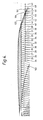
- the sheet is approximately at position 45, that is to say at approximately 45 degrees before top dead centre, when the stop means 107 moves through the plane containing the surface of the table 104.
- the sheet contacts the inclined face 110 of the stop means 107 approximately at position 32 and rides up the face 110 until it contacts the location face 111 at approximately 15 degrees before top dead centre, when it is abruptly decelerated to the speed of the stop means 107, that is to say to substantially the constant peripheral speed of the cylinders, and then continues to advance at that speed until it has been subsequently gripped and then rolled through the nip.
- One advantage of not needing to accelerate the sheet is that high pusher forces are no longer required. This enables thinner or softer sheets to be fed to the press, for example steel sheets only 0.12 mm. thick, or aluminium sheets.
- Another advan tage resulting from the lower pusher force is that sideways location of the sheets, which is particularly difficult when the sheets are not square or rectangular, is rendered easier.
- a further advantage resulting from each sheet travelling at its correct speed and position for a significant length of time prior to entering the nip is that accurate registration of the sheets is achieved, enabling higher printing speeds to be employed.
- ambit of the invention includes stop means moveable relative to the impression cylinder in a true involute path as well as in an arcuate or other path approximating closely to an involute curve.
Landscapes
- Engineering & Computer Science (AREA)
- Mechanical Engineering (AREA)
- Supply, Installation And Extraction Of Printed Sheets Or Plates (AREA)
- Inking, Control Or Cleaning Of Printing Machines (AREA)
- Transmission Devices (AREA)
Applications Claiming Priority (2)
| Application Number | Priority Date | Filing Date | Title |
|---|---|---|---|
| GB898918175A GB8918175D0 (en) | 1989-08-09 | 1989-08-09 | A method of and apparatus for printing on metal sheets |
| GB8918175 | 1989-08-09 |
Publications (3)
| Publication Number | Publication Date |
|---|---|
| EP0412720A2 true EP0412720A2 (de) | 1991-02-13 |
| EP0412720A3 EP0412720A3 (en) | 1991-05-08 |
| EP0412720B1 EP0412720B1 (de) | 1994-12-07 |
Family
ID=10661380
Family Applications (1)
| Application Number | Title | Priority Date | Filing Date |
|---|---|---|---|
| EP19900308512 Expired - Lifetime EP0412720B1 (de) | 1989-08-09 | 1990-08-02 | Vorrichtung und Verfahren zum Bedrucken von Metallplatten |
Country Status (3)
| Country | Link |
|---|---|
| EP (1) | EP0412720B1 (de) |
| DE (2) | DE69014762T2 (de) |
| GB (1) | GB8918175D0 (de) |
Cited By (4)
| Publication number | Priority date | Publication date | Assignee | Title |
|---|---|---|---|---|
| EP0502481A1 (de) * | 1991-03-04 | 1992-09-09 | Fuji Kikai Kogyo Kabushiki Kaisha | Vorrichtung zur Positionierung von Druckstücken zum Gebrauch in einer Druckmaschine |
| EP0596337A1 (de) * | 1992-11-05 | 1994-05-11 | MAN Roland Druckmaschinen AG | Vorrichtung für das registergerechte Anlegen von Druckplatten auf dem Plattenzylinder von Druckmaschinen |
| US5339731A (en) * | 1991-12-03 | 1994-08-23 | Crown Cork & Seal Company, Inc. | Method and apparatus for printing multicolored container body blanks in a single pass |
| CN104703799A (zh) * | 2012-07-06 | 2015-06-10 | Kba金属印刷有限公司 | 用于传送单张承印材料、特别是刚性板的传送设备和方法 |
Families Citing this family (1)
| Publication number | Priority date | Publication date | Assignee | Title |
|---|---|---|---|---|
| DE102012211784A1 (de) | 2012-07-06 | 2014-01-09 | Kba-Metalprint Gmbh | Fördervorrichtung und ein Verfahren zum Fördern von Bedruckstoffbogen |
Family Cites Families (2)
| Publication number | Priority date | Publication date | Assignee | Title |
|---|---|---|---|---|
| US2699941A (en) * | 1949-12-15 | 1955-01-18 | Huck Company | Registering and gripper means for sheet-fed printing presses |
| US2809831A (en) * | 1954-11-10 | 1957-10-15 | American Can Co | Sheet feeding and gauging mechanism |
-
1989
- 1989-08-09 GB GB898918175A patent/GB8918175D0/en active Pending
-
1990
- 1990-08-02 DE DE1990614762 patent/DE69014762T2/de not_active Expired - Fee Related
- 1990-08-02 EP EP19900308512 patent/EP0412720B1/de not_active Expired - Lifetime
- 1990-08-02 DE DE1990308512 patent/DE412720T1/de active Pending
Cited By (5)
| Publication number | Priority date | Publication date | Assignee | Title |
|---|---|---|---|---|
| EP0502481A1 (de) * | 1991-03-04 | 1992-09-09 | Fuji Kikai Kogyo Kabushiki Kaisha | Vorrichtung zur Positionierung von Druckstücken zum Gebrauch in einer Druckmaschine |
| US5253583A (en) * | 1991-03-04 | 1993-10-19 | Fuji Kikai Kogyo Kabushiki Kaisha | Device for positioning printing material for use in a printing apparatus |
| US5339731A (en) * | 1991-12-03 | 1994-08-23 | Crown Cork & Seal Company, Inc. | Method and apparatus for printing multicolored container body blanks in a single pass |
| EP0596337A1 (de) * | 1992-11-05 | 1994-05-11 | MAN Roland Druckmaschinen AG | Vorrichtung für das registergerechte Anlegen von Druckplatten auf dem Plattenzylinder von Druckmaschinen |
| CN104703799A (zh) * | 2012-07-06 | 2015-06-10 | Kba金属印刷有限公司 | 用于传送单张承印材料、特别是刚性板的传送设备和方法 |
Also Published As
| Publication number | Publication date |
|---|---|
| DE69014762D1 (de) | 1995-01-19 |
| DE69014762T2 (de) | 1995-04-13 |
| EP0412720B1 (de) | 1994-12-07 |
| GB8918175D0 (en) | 1989-09-20 |
| EP0412720A3 (en) | 1991-05-08 |
| DE412720T1 (de) | 1991-10-17 |
Similar Documents
| Publication | Publication Date | Title |
|---|---|---|
| US4019435A (en) | Sheet inverting | |
| US4132403A (en) | Sheet transfer apparatus for printing machine | |
| CA1287255C (en) | Sheet transport arrangement for printing machine | |
| US2528106A (en) | Sheet registering mechanism | |
| US3443808A (en) | Sheet gripper mechanism | |
| US4037530A (en) | Mandrel trip mechanism for can printers | |
| EP0412720B1 (de) | Vorrichtung und Verfahren zum Bedrucken von Metallplatten | |
| JPH05261894A (ja) | 枚葉紙を側方に見当合せするための方法と装置 | |
| US4184673A (en) | Method of and an apparatus for aligning sheets advancing in an overlapping array to a printing machine | |
| US4674739A (en) | Sheet transfer device | |
| US4907942A (en) | Arrangement for separating paper sheet pads from a stack | |
| CA2089898C (en) | Device for conveying printed sheets in an installation for checking the quality of paper money | |
| US2809831A (en) | Sheet feeding and gauging mechanism | |
| EP0403814A3 (de) | Bogenzuführung | |
| GB1030269A (en) | Impression cylinder combination for a press | |
| CN1144770A (zh) | 引入辅助堆纸器的方法 | |
| CA1099589A (en) | Duplexing copying system | |
| DE60004113D1 (de) | Fördervorrichtung für bogenförmige Gegenstände in einer Bogenrotationsdruckmaschine | |
| US2699940A (en) | Registering means for sheet-fed printing presses | |
| JPH0325390B2 (de) | ||
| US5265866A (en) | Device for feeding and further processing printing material in sheet-fed rotary printing presses | |
| US5732628A (en) | Sheet-conveying drum for printing machines | |
| CN87102813A (zh) | 旋转印刷机的保护装置 | |
| GB2255331A (en) | Feeding, aligning and holding sheets in sheet-processing machines | |
| US4565359A (en) | Folding apparatus for a web-fed rotary printing press |
Legal Events
| Date | Code | Title | Description |
|---|---|---|---|
| PUAI | Public reference made under article 153(3) epc to a published international application that has entered the european phase |
Free format text: ORIGINAL CODE: 0009012 |
|
| AK | Designated contracting states |
Kind code of ref document: A2 Designated state(s): DE FR GB NL |
|
| PUAL | Search report despatched |
Free format text: ORIGINAL CODE: 0009013 |
|
| AK | Designated contracting states |
Kind code of ref document: A3 Designated state(s): DE FR GB NL |
|
| EL | Fr: translation of claims filed | ||
| TCNL | Nl: translation of patent claims filed | ||
| DET | De: translation of patent claims | ||
| 17P | Request for examination filed |
Effective date: 19911016 |
|
| 17Q | First examination report despatched |
Effective date: 19930713 |
|
| GRAA | (expected) grant |
Free format text: ORIGINAL CODE: 0009210 |
|
| AK | Designated contracting states |
Kind code of ref document: B1 Designated state(s): DE FR GB NL |
|
| ET | Fr: translation filed | ||
| REF | Corresponds to: |
Ref document number: 69014762 Country of ref document: DE Date of ref document: 19950119 |
|
| PLBE | No opposition filed within time limit |
Free format text: ORIGINAL CODE: 0009261 |
|
| STAA | Information on the status of an ep patent application or granted ep patent |
Free format text: STATUS: NO OPPOSITION FILED WITHIN TIME LIMIT |
|
| 26N | No opposition filed | ||
| REG | Reference to a national code |
Ref country code: GB Ref legal event code: IF02 |
|
| PGFP | Annual fee paid to national office [announced via postgrant information from national office to epo] |
Ref country code: FR Payment date: 20020828 Year of fee payment: 13 |
|
| PGFP | Annual fee paid to national office [announced via postgrant information from national office to epo] |
Ref country code: GB Payment date: 20020829 Year of fee payment: 13 |
|
| PGFP | Annual fee paid to national office [announced via postgrant information from national office to epo] |
Ref country code: NL Payment date: 20020830 Year of fee payment: 13 |
|
| PGFP | Annual fee paid to national office [announced via postgrant information from national office to epo] |
Ref country code: DE Payment date: 20021031 Year of fee payment: 13 |
|
| PG25 | Lapsed in a contracting state [announced via postgrant information from national office to epo] |
Ref country code: GB Free format text: LAPSE BECAUSE OF NON-PAYMENT OF DUE FEES Effective date: 20030802 |
|
| PG25 | Lapsed in a contracting state [announced via postgrant information from national office to epo] |
Ref country code: NL Free format text: LAPSE BECAUSE OF NON-PAYMENT OF DUE FEES Effective date: 20040301 |
|
| PG25 | Lapsed in a contracting state [announced via postgrant information from national office to epo] |
Ref country code: DE Free format text: LAPSE BECAUSE OF NON-PAYMENT OF DUE FEES Effective date: 20040302 |
|
| GBPC | Gb: european patent ceased through non-payment of renewal fee |
Effective date: 20030802 |
|
| PG25 | Lapsed in a contracting state [announced via postgrant information from national office to epo] |
Ref country code: FR Free format text: LAPSE BECAUSE OF NON-PAYMENT OF DUE FEES Effective date: 20040430 |
|
| NLV4 | Nl: lapsed or anulled due to non-payment of the annual fee |
Effective date: 20040301 |
|
| REG | Reference to a national code |
Ref country code: FR Ref legal event code: ST |